1 © 1999, cisco systems, inc. 204 0977_05f9_c2 1 nw’99 vienna © 1999, cisco systems, inc. mpls...
TRANSCRIPT

1© 1999, Cisco Systems, Inc.
2040977_05F9_c2 1NW’99 Vienna © 1999, Cisco Systems, Inc.
MPLS VPNsMPLS VPNs
Peter Tomsu
Senior Consultant EMEA
Peter Tomsu
Senior Consultant EMEA

2Mpls_vpns_09_01 © 2001, Peter Tomsu Mpls_vpns 2© 2000, Cisco Systems, Inc.
AgendaAgenda
• VPN Concepts
• MPLS VPN Connectivity Model
• Route Distribution Mechanisms
• Table Population and Packet Forwarding
• Advanced MPLS VPN Topologies
• MPLS VPN Convergence

3© 1999, Cisco Systems, Inc.
2040977_05F9_c2 3NW’99 Vienna © 1999, Cisco Systems, Inc. 3© 2000, Cisco Systems, Inc.
VPN ConceptsVPN Concepts
4Mpls_vpns_09_01 © 2001, Peter Tomsu Mpls_vpns
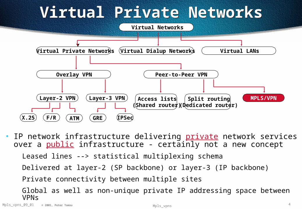
Virtual Private NetworksVirtual Private NetworksVirtual Networks
Virtual Private Networks Virtual Dialup Networks Virtual LANs
Overlay VPN Peer-to-Peer VPN
Layer-2 VPN Layer-3 VPN
X.25 F/R ATM GRE IPSec
Access lists(Shared router)
Split routing(Dedicated router)
MPLS/VPN
• IP network infrastructure delivering private network services over a public infrastructure - certainly not a new concept
Leased lines --> statistical multiplexing schema
Delivered at layer-2 (SP backbone) or layer-3 (IP backbone)
Private connectivity between multiple sites
Global as well as non-unique private IP addressing space between VPNs
5Mpls_vpns_09_01 © 2001, Peter Tomsu Mpls_vpns
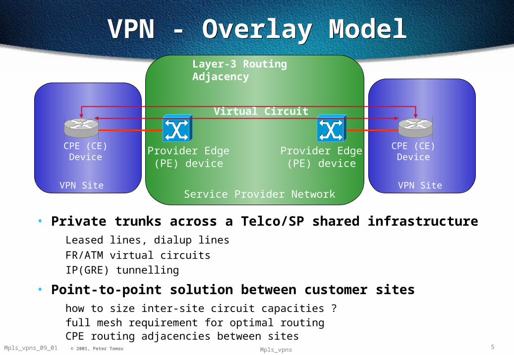
VPN - Overlay ModelVPN - Overlay Model
Service Provider Network
Provider Edge (PE) device
Provider Edge (PE) device
VPN Site VPN Site
Virtual Circuit
CPE (CE) Device
CPE (CE) Device
Layer-3 Routing Adjacency
• Private trunks across a Telco/SP shared infrastructureLeased lines, dialup lines
FR/ATM virtual circuits
IP(GRE) tunnelling
• Point-to-point solution between customer siteshow to size inter-site circuit capacities ?full mesh requirement for optimal routingCPE routing adjacencies between sites
6Mpls_vpns_09_01 © 2001, Peter Tomsu Mpls_vpns
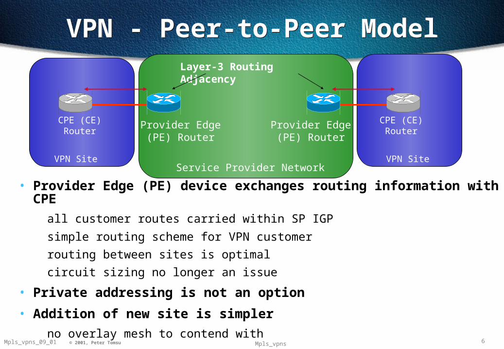
Service Provider Network
Provider Edge (PE) Router
Provider Edge (PE) Router
VPN Site VPN Site
CPE (CE) Router
CPE (CE) Router
Layer-3 Routing Adjacency
VPN - Peer-to-Peer ModelVPN - Peer-to-Peer Model
• Provider Edge (PE) device exchanges routing information with CPE
all customer routes carried within SP IGP
simple routing scheme for VPN customer
routing between sites is optimal
circuit sizing no longer an issue
• Private addressing is not an option
• Addition of new site is simpler
no overlay mesh to contend with
7Mpls_vpns_09_01 © 2001, Peter Tomsu Mpls_vpns
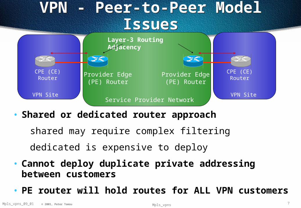
• Shared or dedicated router approach
shared may require complex filtering
dedicated is expensive to deploy
• Cannot deploy duplicate private addressing between customers
• PE router will hold routes for ALL VPN customers
VPN - Peer-to-Peer Model IssuesVPN - Peer-to-Peer Model Issues
Service Provider Network
Provider Edge (PE) Router
Provider Edge (PE) Router
VPN Site VPN Site
CPE (CE) Router
CPE (CE) Router
Layer-3 Routing Adjacency

8Mpls_vpns_09_01 © 2001, Peter Tomsu Mpls_vpns
Solution - MPLS/VPN ModelSolution - MPLS/VPN Model
• Combine benefits of overlay and peer-to-peer models overlay (security and isolation between customers)peer-to-peer (simplified customer routing)
• PE routers only hold routes for attached VPNsreduces size of PE routing informationproportional to number of VPNs attached
• MPLS used to forward packets (no mor via routing)full routing within backbone no longer required means
no more external routing info needed in backbone
P-Network
PE Router PE Router
C-Network
CE Router CE Router
VPN Site
P Router
VPN Site

9© 1999, Cisco Systems, Inc.
2040977_05F9_c2 9NW’99 Vienna © 1999, Cisco Systems, Inc. 9© 2000, Cisco Systems, Inc.
MPLS VPN Connectivity Model
MPLS VPN Connectivity Model

10Mpls_vpns_09_01 © 2001, Peter Tomsu Mpls_vpns
MPLS/VPN Connectivity ModelMPLS/VPN Connectivity Model
• A VPN is a collection of sites sharing common routing information
same set of routes within the routing table
• A site may belong to more than one VPN
through sharing of routing information
• A VPN can be seen as Closed User Group (CUG) or Community of Interest
P-Network
PE Router PE Router
C-Network
CE Router CE Router
VPN Site
P Router
VPN Site

11Mpls_vpns_09_01 © 2001, Peter Tomsu Mpls_vpns
VPN Routing & Forwarding Instance – VRF &Global Routing Table
VPN Routing & Forwarding Instance – VRF &Global Routing Table
PE
CE
VPN-A
VPN-A
CEVPN-B
VRF for VPN-A
VRF for VPN-B
VPN Routing Table
CE
Global Routing Table
IGP &/or BGP
Paris
London
Munich
• Global routing table
contains all PE and P routes populated by the VPN backbone IGP
• VRF (VPN Routing & Forwarding Instance)
associated with one or more directly connected sites (CE routers)
associated with any type of interface, whether logical or physical (e.g. sub/virtual/tunnel)
interfaces may share same VRF if connected sites share same routing information
12Mpls_vpns_09_01 © 2001, Peter Tomsu Mpls_vpns
VPN Routing & Forwarding Instance (VRF)
VPN Routing & Forwarding Instance (VRF)
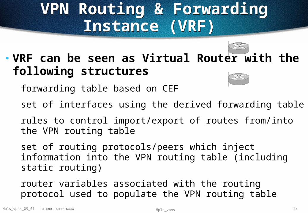
• VRF can be seen as Virtual Router with the following structures
forwarding table based on CEF
set of interfaces using the derived forwarding table
rules to control import/export of routes from/into the VPN routing table
set of routing protocols/peers which inject information into the VPN routing table (including static routing)
router variables associated with the routing protocol used to populate the VPN routing table
13Mpls_vpns_09_01 © 2001, Peter Tomsu Mpls_vpns
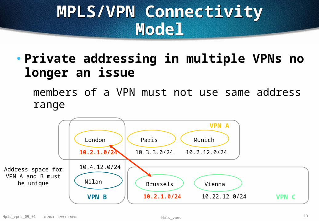
MPLS/VPN Connectivity ModelMPLS/VPN Connectivity Model
• Private addressing in multiple VPNs no longer an issue
members of a VPN must not use same address range
VPN A
VPN B VPN C
London
Milan
Paris Munich
Brussels Vienna
Address space for VPN A and B must be unique
10.2.1.0/24 10.22.12.0/24
10.2.1.0/24 10.3.3.0/24 10.2.12.0/24
10.4.12.0/24

14Mpls_vpns_09_01 © 2001, Peter Tomsu Mpls_vpns
VRF Route PopulationVRF Route Population
• VRF populated locally through PE and CE routing protocol exchange
RIP Version 2, OSPF, BGP-4 & Static routing
• Separate routing context for each VRF
routing protocol context (BGP-4 & RIP V2)
separate process (OSPF)
PE
CE
CE
Site-2
Site-1
EBGP,OSPF, RIPv2,Static
15Mpls_vpns_09_01 © 2001, Peter Tomsu Mpls_vpns
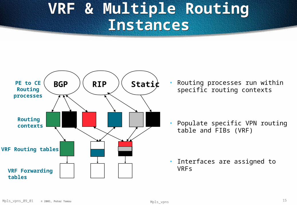
StaticBGP RIPPE to CE Routing
processes
Routing contexts
VRF Routing tables
VRF Forwarding tables
• Routing processes run within specific routing contexts
• Populate specific VPN routing table and FIBs (VRF)
• Interfaces are assigned to VRFs
VRF & Multiple Routing InstancesVRF & Multiple Routing Instances
16© 1999, Cisco Systems, Inc.
2040977_05F9_c2 16NW’99 Vienna © 1999, Cisco Systems, Inc. 16© 2000, Cisco Systems, Inc.
MPLS VPN Route Distribution
Mechanisms
MPLS VPN Route Distribution
Mechanisms

17Mpls_vpns_09_01 © 2001, Peter Tomsu Mpls_vpns
VRF Population with MP-iBGPVRF Population with MP-iBGP
PE
CE
VPN-A
VPN-A
CEVPN-B
VRF VPN-A VRF VPN-B
CE
MP-iBGP
PE
BGP Tabe
Routes from VPN-A Routes from VPN-B
Paris
London
Munich
• Global Routing Table populated by IGP protocols (e.g. OSPF, IS-IS)
may also contain BGP-4 (IPv4) routes
does not contain VPN routes
• VRF routing tables contain VPN specific routes
MP-iBGP routes imported into VRFs
CE routes populate VRFs based on routing protocol context
Global Routing Table
IGP &/or BGP
18Mpls_vpns_09_01 © 2001, Peter Tomsu Mpls_vpns
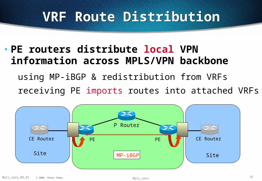
VRF Route DistributionVRF Route Distribution
• PE routers distribute local VPN information across MPLS/VPN backbone
using MP-iBGP & redistribution from VRFs
receiving PE imports routes into attached VRFs
PE PE CE Router CE Router
P Router
Site Site MP-iBGP

19Mpls_vpns_09_01 © 2001, Peter Tomsu Mpls_vpns
Receiving PE Router InfoReceiving PE Router Info
Extended Community Attribute• BGP transitive optional attribute which contains a set of extended communities
SOO - Site of Origin
identifies the site that originated a particular route
RT - Route Target
identifies set of sites to which a particular route should be exported to
Route Distinguisher • Uniqueness of IPv4 prefix achieved through the use of a
RD - 64 bit identifier
creates a VPN-V4 Prefix
RD + IPv4 Prefix
20Mpls_vpns_09_01 © 2001, Peter Tomsu Mpls_vpns
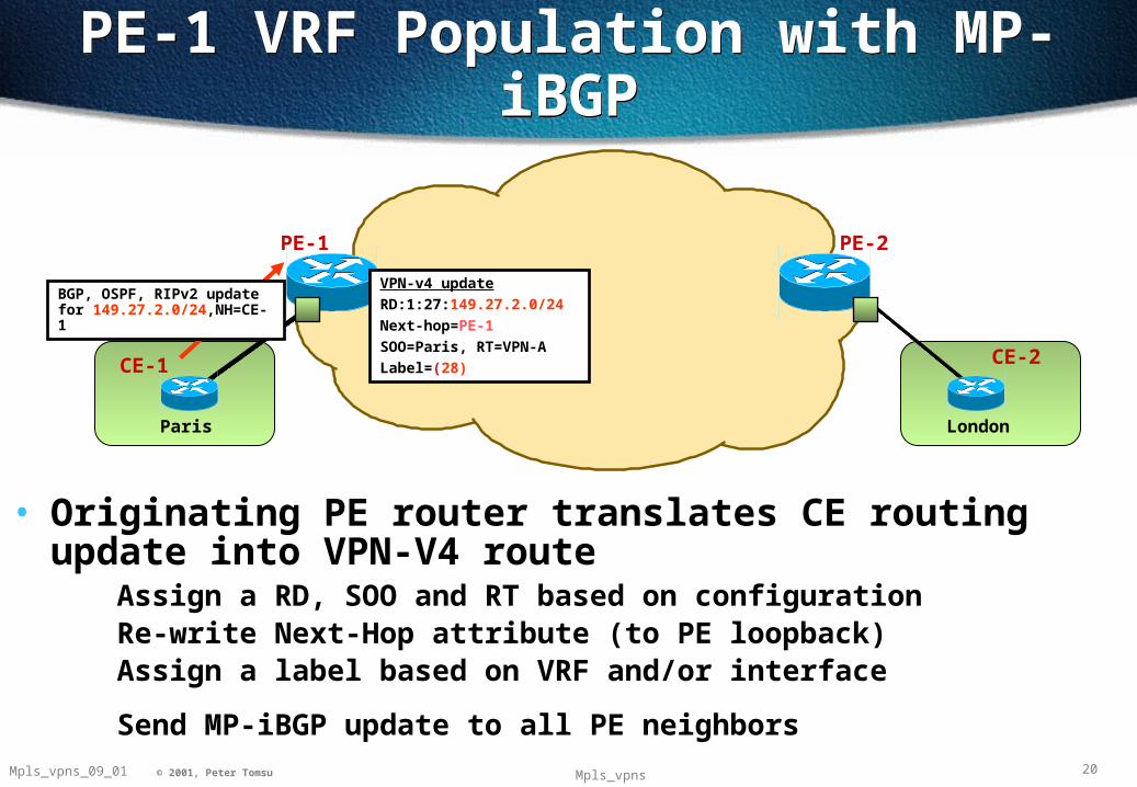
PE-1 VRF Population with MP-iBGPPE-1 VRF Population with MP-iBGP
PE-1
CE-1
PE-2
BGP, OSPF, RIPv2 update for 149.27.2.0/24,NH=CE-1
VPN-v4 update
RD:1:27:149.27.2.0/24
Next-hop=PE-1
SOO=Paris, RT=VPN-A
Label=(28)CE-2
• Originating PE router translates CE routing update into VPN-V4 route
Assign a RD, SOO and RT based on configurationRe-write Next-Hop attribute (to PE loopback)Assign a label based on VRF and/or interface
Send MP-iBGP update to all PE neighbors
Paris London
21Mpls_vpns_09_01 © 2001, Peter Tomsu Mpls_vpns
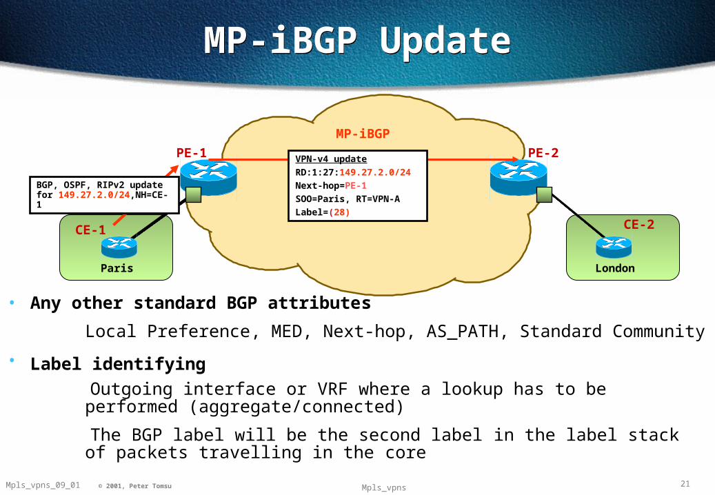
MP-iBGP UpdateMP-iBGP Update
PE-1
CE-1
MP-iBGP
PE-2
BGP, OSPF, RIPv2 update for 149.27.2.0/24,NH=CE-1
CE-2
Paris London
• Any other standard BGP attributes
Local Preference, MED, Next-hop, AS_PATH, Standard Community
• Label identifying
Outgoing interface or VRF where a lookup has to be performed (aggregate/connected)
The BGP label will be the second label in the label stack of packets travelling in the core
VPN-v4 update
RD:1:27:149.27.2.0/24
Next-hop=PE-1
SOO=Paris, RT=VPN-A
Label=(28)
22Mpls_vpns_09_01 © 2001, Peter Tomsu Mpls_vpns
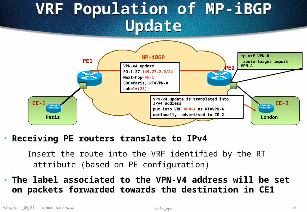
VRF Population of MP-iBGP UpdateVRF Population of MP-iBGP Update
PE1
CE-1
MP-iBGP
PE2
ip vrf VPN-B
route-target import VPN-A
CE-2
• Receiving PE routers translate to IPv4
Insert the route into the VRF identified by the RT attribute (based on PE configuration)
• The label associated to the VPN-V4 address will be set on packets forwarded towards the destination in CE1
VPN-v4 update is translated into IPv4 address
put into VRF VPN-A as RT=VPN-A
optionally advertised to CE-2Paris London
VPN-v4 update
RD:1:27:149.27.2.0/24
Next-hop=PE-1
SOO=Paris, RT=VPN-A
Label=(28)
23Mpls_vpns_09_01 © 2001, Peter Tomsu Mpls_vpns
P RouterP Router
MPLS/VPN BackboneMPLS/VPN BackboneVPN A VPN A
VPN A
SITE-2SITE-2
VPN A
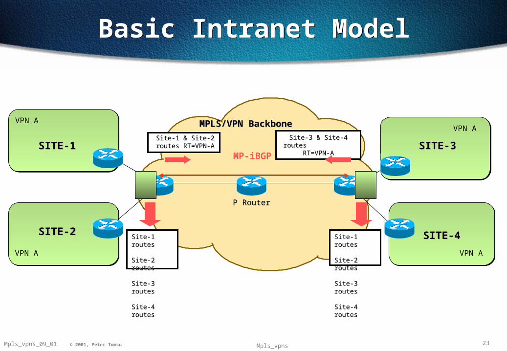
Site-1 routes Site-1 routes Site-2 Site-2 routes routes Site-3 routes Site-3 routes Site-4 Site-4 routesroutes
MP-iBGP
Basic Intranet ModelBasic Intranet Model
Site-3 & Site-4 routes Site-3 & Site-4 routes RT=VPN-A RT=VPN-A
Site-1 & Site-2 routes Site-1 & Site-2 routes RT=VPN-ART=VPN-A
Site-1 routes Site-1 routes Site-2 Site-2 routes routes Site-3 routes Site-3 routes Site-4 Site-4 routesroutes
SITE-1SITE-1 SITE-3SITE-3
SITE-4SITE-4

24© 1999, Cisco Systems, Inc.
2040977_05F9_c2 24NW’99 Vienna © 1999, Cisco Systems, Inc. 24© 2000, Cisco Systems, Inc.
MPLS VPNTable Population
&Packet Forwarding
MPLS VPNTable Population
&Packet Forwarding

25Mpls_vpns_09_01 © 2001, Peter Tomsu Mpls_vpns
P routerP router
In Label FEC Out Label
- 197.26.15.1/32 -
In Label FEC Out Label
41 197.26.15.1/32 POP
In Label FEC Out Label
41 197.26.15.1/32 -
MPLS/VPN Table PopulationMPLS/VPN Table Population
Paris
Use label implicit-null for destination 197.26.15.1/32
Use label 41 for destination 197.26.15.1/32
PE-1
London
• PE and P routers have BGP next-hop reachability through the backbone IGP
• Labels are distributed through LDP corresponding to BGP Next-Hops
or RSVP with Traffic Engineering
149.27.2.0/24
VPN-v4 update
RD:1:27:149.27.2.0/24
Next-hop=PE-1
SOO=Paris, RT=VPN-A
Label=(28)
197.26.15.1 197.26.15.2
26Mpls_vpns_09_01 © 2001, Peter Tomsu Mpls_vpns
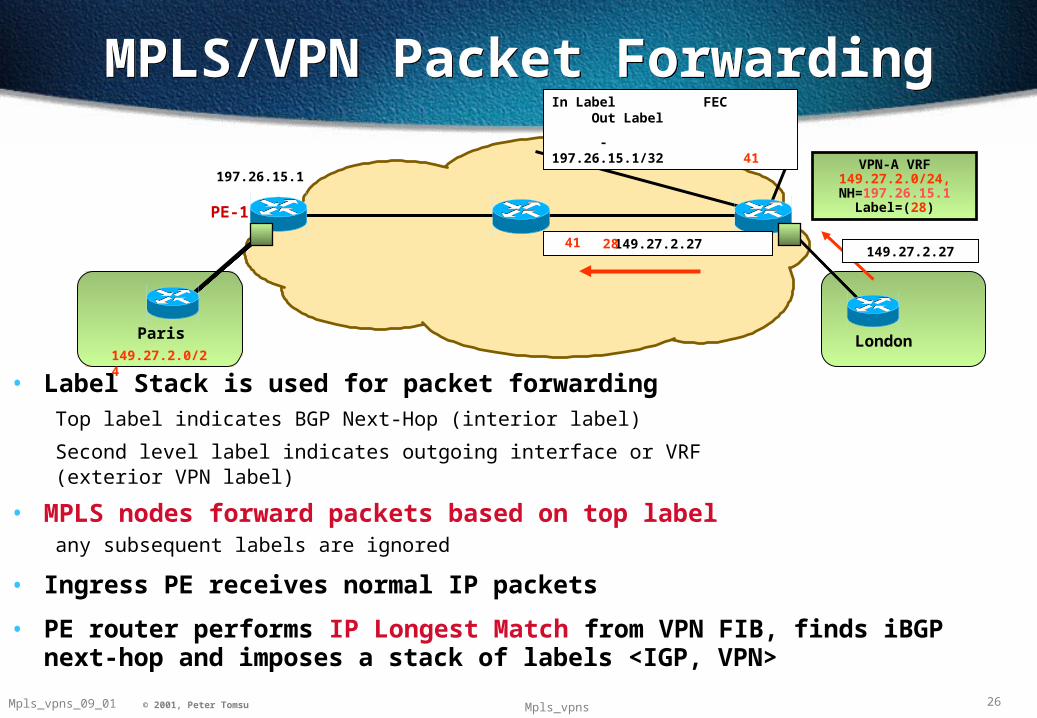
MPLS/VPN Packet ForwardingMPLS/VPN Packet Forwarding
• Label Stack is used for packet forwardingTop label indicates BGP Next-Hop (interior label)
Second level label indicates outgoing interface or VRF(exterior VPN label)
• MPLS nodes forward packets based on top labelany subsequent labels are ignored
• Ingress PE receives normal IP packets
• PE router performs IP Longest Match from VPN FIB, finds iBGP next-hop and imposes a stack of labels <IGP, VPN>
In Label FEC Out Label
- 197.26.15.1/32 41
Paris
149.27.2.27
PE-1
London149.27.2.0/24
149.27.2.272841
VPN-A VRF149.27.2.0/24,
NH=197.26.15.1Label=(28)
197.26.15.1
27Mpls_vpns_09_01 © 2001, Peter Tomsu Mpls_vpns
In Label FEC Out Label
41 197.26.15.1/32 POP
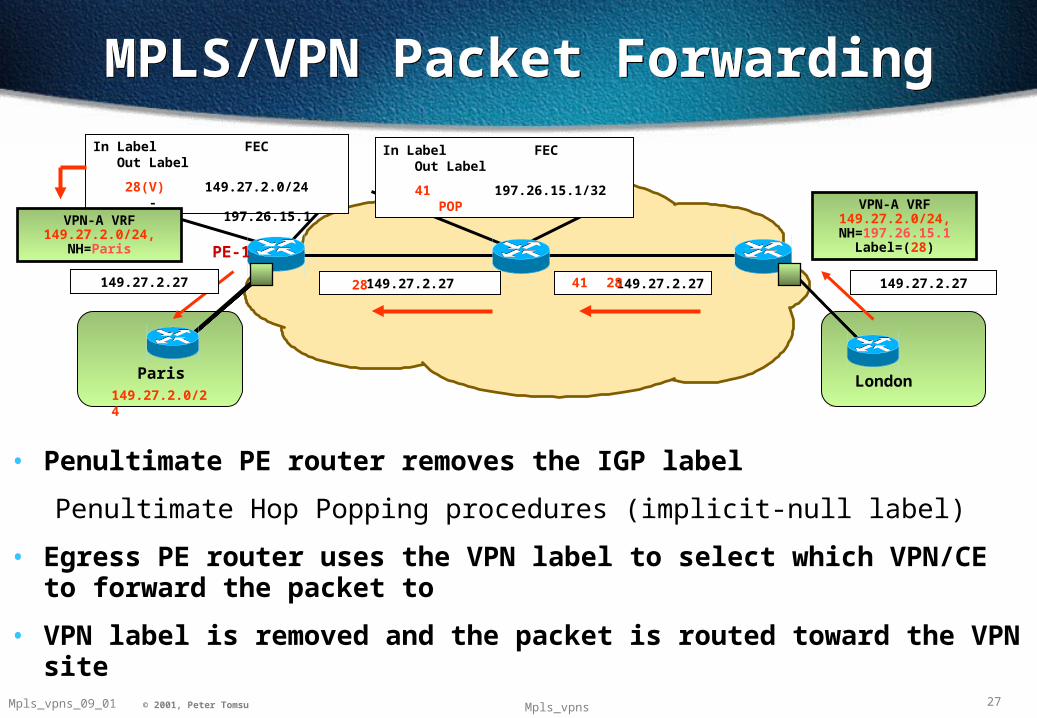
MPLS/VPN Packet ForwardingMPLS/VPN Packet Forwarding
Paris
149.27.2.27
PE-1
London149.27.2.0/24
149.27.2.272841
VPN-A VRF149.27.2.0/24,
NH=197.26.15.1Label=(28)
149.27.2.2728
In Label FEC Out Label
28(V) 149.27.2.0/24 -
VPN-A VRF149.27.2.0/24,
NH=Paris
149.27.2.27
• Penultimate PE router removes the IGP label
Penultimate Hop Popping procedures (implicit-null label)
• Egress PE router uses the VPN label to select which VPN/CE to forward the packet to
• VPN label is removed and the packet is routed toward the VPN site
197.26.15.1

28© 1999, Cisco Systems, Inc.
2040977_05F9_c2 28NW’99 Vienna © 1999, Cisco Systems, Inc. 28© 2000, Cisco Systems, Inc.
Advanced MPLS VPN Topologies
Advanced MPLS VPN Topologies

29Mpls_vpns_09_01 © 2001, Peter Tomsu Mpls_vpns
MPLS/VPN Extranet SupportMPLS/VPN Extranet Support
PE
VPN-A
VPN-A
CE
VPN-B
VRF for VPN-A
VRF for VPN-B
VPN-A Paris Routes VPN-B Munich RoutesCE
Extranet VPN Routing Table
Paris
Munich
• Extranet support is simply the import of routes from one VRF into another VRF which services a different VPN
• Controlled through the use of route target
if we import the route, we have access
• Various topologies are viable using this technique
30Mpls_vpns_09_01 © 2001, Peter Tomsu Mpls_vpns
Central Services Model
VPN A
Central Server Site
VPN B
195.12.2.0/24
146.12.7.0/24
146.12.9.0/24
VPN A VRFVPN A VRF 195.12.2.0/24 195.12.2.0/24 146.12.9.0/24146.12.9.0/24
VPN B VRFVPN B VRF 146.12.7.0/24 146.12.7.0/24 146.12.9.0/24146.12.9.0/24
VPN A VRF (Export RT=client-rt) (Import
RT=server-rt)
VPN B VRF (Export RT=client-rt) (Import
RT=server-rt)
Server VRF (Export RT=server-rt) (Import RT=server-rt) (Import
RT=client-rt)
MP-iBGP Update RD:195.12.2.0/24,
RT=client-rt
MP-iBGP Update RD:146.12.9.0/24,
RT=server-rt
MP-iBGP Update RD:146.12.7.0/24,
RT=client-rt
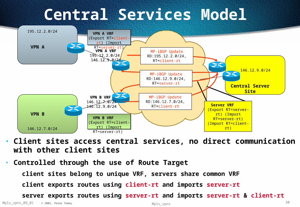
• Client sites access central services, no direct communication with other client sites
• Controlled through the use of Route Target
client sites belong to unique VRF, servers share common VRF
client exports routes using client-rt and imports server-rt
server exports routes using server-rt and imports server-rt & client-rt

31Mpls_vpns_09_01 © 2001, Peter Tomsu Mpls_vpns
MPLS/VPN Internet ConnectivityStatic Default Route
MPLS/VPN Internet ConnectivityStatic Default Route
VPN A
195.12.2.0/24
Global Internet Access
VPN B
VPN A VRFVPN A VRF 0.0.0.0 0.0.0.0 NH=Internet-PENH=Internet-PE
VPN B VRFVPN B VRF 0.0.0.0 0.0.0.0 NH=Internet PENH=Internet PE
Internet Routing TableInternet Routing Table
MPLS/VPN BackboneMPLS/VPN Backbone
ip route vrf VPN_A 0.0.0.0 0.0.0.0 Internet-PE global ip route 195.12.2.0 255.255.255.0 serial 1/0
ip route vrf VPN_B 0.0.0.0 0.0.0.0 Internet-PE global ip route 146.12.9.0 255.255.255.0 serial 1/1
146.12.9.0/24
• Default route provided through static route within the VRF
extension to ‘ip route’ command - Global keyword
Internet gateway points to an exit point whose address is within the global routing table
• PE router generates VPN customer routes into BGP through global static routes
32Mpls_vpns_09_01 © 2001, Peter Tomsu Mpls_vpns
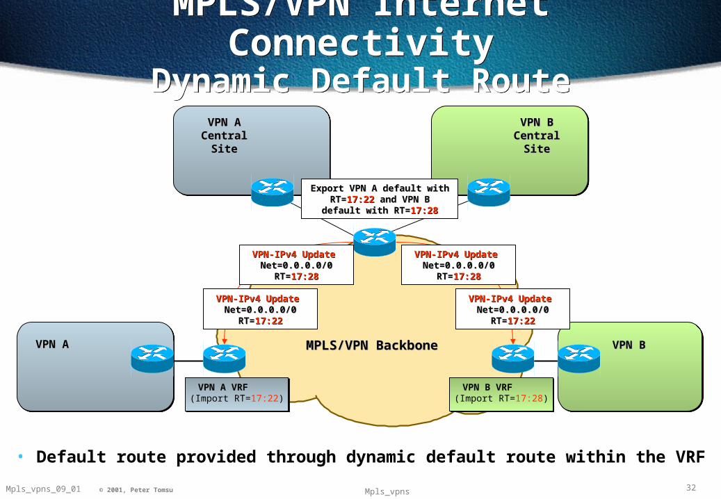
MPLS/VPN Internet ConnectivityDynamic Default Route
MPLS/VPN Internet ConnectivityDynamic Default Route
MPLS/VPN BackboneMPLS/VPN BackboneVPN AVPN A
VPN A Central VPN A Central SiteSite
VPN B Central VPN B Central SiteSite
VPN-IPv4 Update VPN-IPv4 Update Net=0.0.0.0/0 RT=Net=0.0.0.0/0 RT=17:2217:22
VPN-IPv4 Update VPN-IPv4 Update Net=0.0.0.0/0 RT=Net=0.0.0.0/0 RT=17:2817:28
VPN-IPv4 Update VPN-IPv4 Update Net=0.0.0.0/0 RT=Net=0.0.0.0/0 RT=17:2817:28
VPN-IPv4 Update VPN-IPv4 Update Net=0.0.0.0/0 RT=Net=0.0.0.0/0 RT=17:2217:22
Export VPN A default with Export VPN A default with RT=RT=17:22 17:22 and VPN B default and VPN B default
with RT=with RT=17:2817:28
VPN A VRF (Import RT=17:22)
VPN B VRF (Import RT=17:28)
VPN BVPN B
• Default route provided through dynamic default route within the VRF
33Mpls_vpns_09_01 © 2001, Peter Tomsu Mpls_vpns
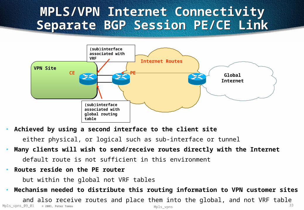
• Achieved by using a second interface to the client site
either physical, or logical such as sub-interface or tunnel
• Many clients will wish to send/receive routes directly with the Internet
default route is not sufficient in this environment
• Routes reside on the PE router
but within the global not VRF tables
• Mechanism needed to distribute this routing information to VPN customer sites
and also receive routes and place them into the global, and not VRF table
MPLS/VPN Internet ConnectivitySeparate BGP Session PE/CE LinkMPLS/VPN Internet Connectivity
Separate BGP Session PE/CE Link
PEVPN Site
Global Internet
Internet Routes
(sub)interface associated with global routing table
(sub)interface associated with VRF
CE

34Mpls_vpns_09_01 © 2001, Peter Tomsu Mpls_vpns
ISP BISP BISP AISP A
Export default route with Export default route with Internet_access route Internet_access route
targettarget
Export default route with Export default route with Internet_access route Internet_access route
targettarget
Full Internet Routes
Full Internet Routes Full Intern
et Routes
Full Intern
et Routes
PEPE
Static default pointing to loopback interface so
lookup in VRF will occur on incoming packets
MPLS/VPN Internet ConnectivityGlobal Internet Table Association
MPLS/VPN Internet ConnectivityGlobal Internet Table Association
• If multiple exit points then possibility to associate full Internet routes with a VRF
if only one exit point then default pointing to internet exit point interface will normally be sufficient
• With multiple interfaces, sub-optimal routing is a possibility with default route generation
as multiple defaults would allow load balancing but no best path selection
• Association of Internet routes with VRF provide ability to generate aggregate default

35© 1999, Cisco Systems, Inc.
2040977_05F9_c2 35NW’99 Vienna © 1999, Cisco Systems, Inc. 35© 2000, Cisco Systems, Inc.
MPLS VPN ConvergenceMPLS VPN Convergence

36Mpls_vpns_09_01 © 2001, Peter Tomsu Mpls_vpns
End-to-end Routing ConvergenceEnd-to-end Routing Convergence
PE PE
VPN VPN Client AClient A
VPN VPN Client AClient A
New VPN route New VPN route advertisedadvertised
Advertisement of new Advertisement of new VPN route to relevant VPN route to relevant
VPN sitesVPN sites
New VPN route New VPN route imported into relevant imported into relevant
VRFsVRFs
New VPN route propagated across MP-iBGP session
If link fails, MPLS/VPN backbone IGP converges on new path to BGP next-hop
• Convergence needs to be assessed in two main areas
convergence within the MPLS/VPN backbone
convergence between VPN client sites
• Both areas are completely independent ..
but work together to provide end-to-end convergence as perceived by the VPN client
therefore must be assessed in conjunction

37Mpls_vpns_09_01 © 2001, Peter Tomsu Mpls_vpns
PE-1
P-1
VPN Client VPN Client AA
VPN Client VPN Client AA
ConvergenceRouter Based Backbone
ConvergenceRouter Based Backbone
MPLS & IGP backbone convergence are closely entwined
If P-1 to PE-2 link fails, PE-1 next-hop to destinations reachable via 197.26.15.1/32 (PE-2 Loopback) will change to P-3. As label exists (41), convergence is as quick as the IGP
PE-2
Use label 41 for destination 197.26.15.1/32 Use label POP for destination
197.26.15.1/32
Use label 23 for destination 197.26.15.1/32
Use label 25 for destination 197.26.15.1/32 P-2
P-3
Use label POP for destination 197.26.15.1/32

38Mpls_vpns_09_01 © 2001, Peter Tomsu Mpls_vpns
PE-1
P-1
VPN Client VPN Client AA
VPN Client VPN Client AA
ConvergenceATM Based Backbone
ConvergenceATM Based Backbone
MPLS LSR must re-converge on IGP change AND re-signal for label mapping to downstream next-hop
If P-1 to PE-2 link fails, PE-1 next-hop to destinations reachable via 197.26.15.1/32 (PE-2 Loopback) will change to P-3. As label does not exist, PE-1 must signal the next-hop downstream ATM-LSR
PE-2
Label request for destination 197.26.15.1/32
Use label 1/239 for destination 197.26.15.1/32
P-2
P-3
Use label 1/321 for destination 197.26.15.1/32
Label request for destination 197.26.15.1/32
Label request for destination 197.26.15.1/32

39Mpls_vpns_09_01 © 2001, Peter Tomsu Mpls_vpns