1. 2 fig. 4.1 3 fig. 4.2 4 fig. 4.3 5 fig. 4.4
TRANSCRIPT

1
ET3380
Week 3
AC-to-DC Converters

2
Three-pulse diode rectifier
Fig. 4.1
LO A D
S U P P LY L IN EA
B
C
N
D A
o
Ai iB iC io
D B D C v

3
Example current path and voltage distribution in a three-pulse diode rectifier
Fig. 4.2
0
v
v v
AN
BN
CN
io iB
= io
vBA vBC
vo = vBN
vBN
D B

4
Waveforms of output voltage and current in a three-pulse diode rectifier (R load)
Fig. 4.3
VLN,p
VLN,p
-
0
io
vo
vBvAvC
2t

5
Waveform of input current in a three-pulse diode rectifier (R load)
Fig. 4.4

6
Six-pulse diode rectifier
Fig. 4.5
A
B
C
L
E
R
vo
DA'
DB' DC'
i iB iA C
DA
DB DC
io

7
Example current path and voltage distribution in a six-pulse diode rectifier
Fig. 4.6
v
A
v
v
B
D A
D B '
L
E
R
io
vo = vAB
C
v
B
v
A
v
AB
v
AB v
AC
v
CB
i A = i o -i = i oB
8
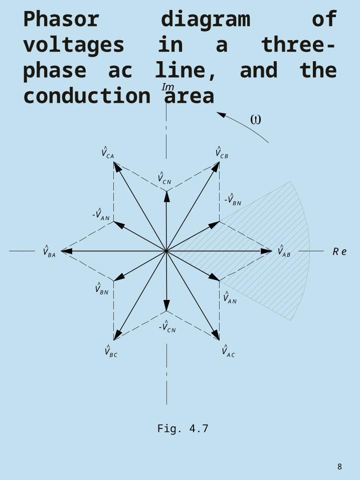
Phasor diagram of voltages in a three-phase ac line, and the conduction area
Fig. 4.7
V^CA V^CB
V^BA
^-V
V^BC V^AC
V^AB
Im
Re
V^CN
^-VAN
V^BN
CN
V^AN
^-VBN

9
Waveforms of output voltage and current in a six-pulse diode rectifier in the continuous conduction mode (RLE load)
Fig. 4.8
VLL,p
VLL,p
-
0
vBA vCA vCB vAB vAC vBC
vo
io
2t

10
Twelve-pulse diode rectifier
Fig. 4.9
SUPPLY LINEA
B
C
D
E
F
LOADvo
^
A
VC
V̂F
^
E
V̂
V̂D
o i
VV̂
B

11
Areas of conduction modes of a six-pulse diode rectifier
Fig. 4.10
LOAD ANGLE (deg)
0 15 30 45 60 75 90
LOA
D E
MF
CO
EF
FIC
IEN
T
0.80
0.85
0.90
0.95
1.00
CONTINUOUS CONDUCTION
DISCONTINUOUS CONDUCTION

12
Waveforms of output voltage and current in a six-pulse diode rectifier in the discontinuous conduction mode (RLE load)
Fig. 4.11
0 c
E
e
io
vBA vCA vCB vAB vAC vBC
vo
2t

13
Waveform of input current in a six-pulse diode rectifier (assuming an ideal dc output current)
Fig. 4.12
iA,1
0
_3
5
- Io,dc
Io,dc
iA
_3
2
2t

14
Spectrum of input current in a six-pulse diode rectifier
Fig. 4.13
HARMONIC NUMBER
0 20 40 60 80 100
AM
PLI
TU
DE
(pu
)
0.001
0.01
0.1
1
10

15
Input filter (harmonic trap) for a three-phase rectifier
Fig. 4.14
F ILT E R 1(5th ha rm onic )
F ILT E R 2(7th ha rm onic )
F ILT E R 3(11 th & 13th ha rm onic s )
R E C T IF IE RPOWER SYST EM

16
Phase-controlled (SCR) six-pulse rectifier
Fig. 4.15
A
B
C
L
E
R
io
vo
i iB iA C
TA TB TC
TA ' TB ' TC '

17
Firing pulses in a phase-controlled six-pulse rectifier
Fig. 4.16

18
Waveforms of output voltage and current in a phase-controlled six-pulse rectifier in the continuous conduction mode (, RLE load)
Fig. 4.17
0 f
io
vBA vCA vCB vAB vAC vBC
vo
2t

19
Control characteristic of a phase-controlled six-pulse rectifier in the continuous conduction mode
Fig. 4.18
FIRING ANGLE (deg)
0 30 60 90 120 150 180
MA
GN
ITU
DE
CO
NT
RO
L R
AT
IO
-1.00
-0.75
-0.50
-0.25
0.00
0.25
0.50
0.75
1.00

20
Rectifier in the inverter mode
Fig. 4.19
A B C
R
E
L
i o
o,dcV

21
Waveforms of output voltage and current in a phase-controlled six-pulse rectifier in the continuous conduction mode
Fig. 4.20
0 f
io
vBA vCA vCB vAB vAC vBC
vo2t

22
Area of feasible firing angles
Fig. 4.21
LOAD EMF COEFFICIENT
-1.0 -0.5 0.0 0.5 1.0
FIR
ING
AN
GLE
(deg)
0
30
60
90
120
150
180
INFEASIBLE
FEASIBLE

23
Conduction mode areas of a phase-controlled six-pulse rectifier
Fig. 4.22
LOAD ANGLE (deg)
0 15 30 45 60 75 90
LOA
D E
MF
CO
EF
FIC
IEN
T
-1.00
-0.75
-0.50
-0.25
0.00
0.25
0.50
0.75
1.00
CO
NT
INU
OU
SDIS
CO
NT
INU
OU
S
f=150o
f=120o
f=90o
f=60o
f=30o
f=0o

24
Waveforms of output voltage and current in a phase-controlled six-pulse rectifier in the discontinuous conduction mode: (a) rectifier operation(b) inverter operation
Fig. 4.23
0 t
(b)
io
vo
ef
E
vBA vCA vCB vAB vAC vBC
2
(a)
0
f
E
e
io
vBA vCA vCB vAB vAC vBC
vo
2t

25
Waveform of input current in a phase-controlled six-pulse rectifier (ideal dc output current assumed)
Fig. 4.24
f
iA,1
0_
3
5
- Io,dc
Io,dc
iA
_3
2 2t

26
Schemes to Generate Firing Pulses for a Dual-Converter.

27
Waveforms of output voltage and current in a phase-controlled six-pulse rectifier supplied from a source with inductance: (a) rectifier mode, (b) inverter mode
Fig. 4.27
0 t
(b)
io
vo
f
vBA vCA vCB vAB vAC vBC
2
(a)
0 f
io
vBA vCA vCB vAB vAC vBC
vo
2t

28
Notched waveform of input voltage in a phase-controlled six-pulse rectifier supplied from a source with inductance
Fig. 4.28
0
vab
2
t

29
Plane of operation, operating area, and operating quadrants of a rectifier
Fig. 4.29
o,dc VIN VER T ER
POSIT IVE VO LTAGE
R EC T IFIER
POSIT IVE VO LTAGE
N EG AT IVE VO LTAGE
R EC T IFIERN EG AT IVE VO LTAGE
IN VER T ER
II I
III IV
o,dc I

30
Controlled rectifier with a cross-switch
Fig. 4.30
A B C
ovv'o
oi
oi'
31
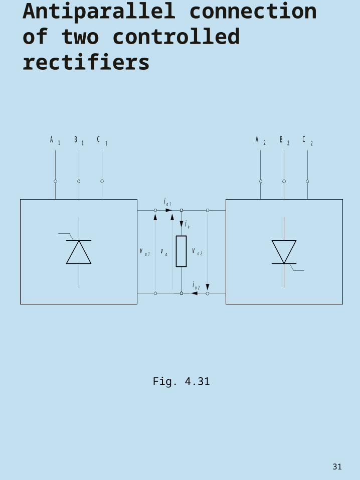
Antiparallel connection of two controlled rectifiers
Fig. 4.31
A 1 B 1 C 1 A B C2 2 2
v
o1i
io
io2
o1
v o2
vo

32
Six-pulse circulating current-free dual converter
Fig. 4.32
B
C
TA2
TB2
A
TA1' TB1' TC1' TC2
ov
R
L
E
TA1
TB1
TC1
TA2' TB2' TC2'
Ai i iB C
io

33
Six-pulse circulating current-conducting dual converter supplied from two separate ac sources
Fig. 4.33
A B C
R
L
E
v o1
L L + i c r i o
+ i c r i o + i c r i o
c ri c ri c ri
i o
vo o2v
1 2
RC T1 RC T2
TA1
TB1'
TA2'
TC2

34
Waveforms of output voltages of constituent rectifiers of a circulating current-conducting dual converter (, )
Fig. 4.34
f2f1
vo2
vo1
0
vBA vCA vCB vAB vAC vBC
2t

35
Waveforms of differential output voltage and circulating current in a circulating current-conducting dual converter ()
Fig. 4.35
icr
vo
02
t

36
Waveforms of differential output voltage and circulating current in a circulating current-conducting dual converter ()
Fig. 4.36
icr
vo
02
t

37
Six-pulse circulating current-conducting dual converter supplied from a single ac source
Fig. 4.37
R
L
E
o
v
o
L L
L L c r2
A B C
i + i c r1 oi
+ i c r2
oi
+ i c r1
oi
+ i c r2RCT1
o1
1
3 4
2
i
o2v
c r1i
ov
iRCT2
TA2'
TC2
TA1
TB1'
c r1i c r2i

38
Next Week
AC-to-DC PWM Converters1. PWM Rectifiers2. Voltage Space Vector3. Current Space Vector4. Current and Voltage Type PWM
Rectifier5. Buck/Boost Converter6. State Selection and Direct
Power Control