1-2 umts radio channel&key technologies
DESCRIPTION
UMTS Radio Channel and Key Technologies.This document comprises topics,Classification of channelsPhysical layer procedureRAKE ReceiverHandover ControlAdmission ControlLoad ControlTRANSCRIPT

UMTS Radio Channel & Key Technologies
ZTE University

Content
Classification of channels Physical layer procedure RAKE Receiver Handover Control Admission Control Load Control
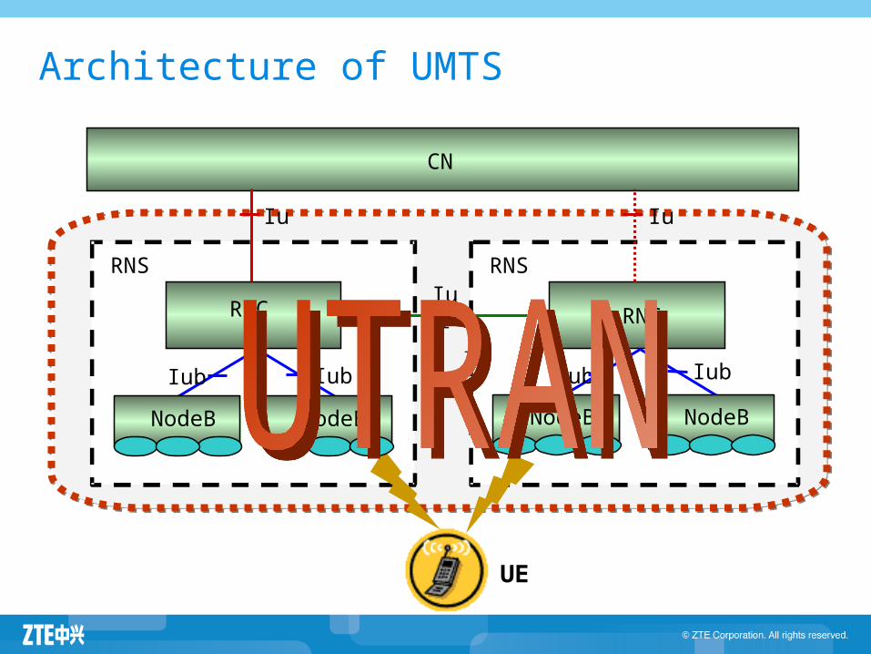
RNS RNS
CN
RNCRNC
Iu Iu
Iur
Iub IubIub Iub
Architecture of UMTS
UE
NodeBNodeBNodeBNodeB

Concept of channel
PHY layer
MAC layer
RLC layer
Transport channel
Physical channel
Logical channel
L1
L2

Channel Type
Logical channels: Describe what is transported (i.e., the information to be
transmitted)
Transport channels: Describe how the logical channels are to be transmitted.
Physical channels: Represent the “transmission media” providing the
platform through which the information is actually transferred.

Logical Channels
Control Channel (CCH) Broadcast Control Channel (BCCH)
Paging Control Channel (PCCH)
Dedicated Control Channel (DCCH)
Common Control Channel (CCCH)
Traffic Channel
(TCH)
Dedicated Traffic Channel (DTCH)
Common Traffic Channel (CTCH)

Transport Channel
Random Access Channel (RACH)
Broadcast Channel (BCH)
Paging Channel (PCH)
Forward Access Channel (FACH)
Common Packet Channel (CPCH)
Common Transport Channels
Dedicated Transport Channels
Downlink Shared Channel (DSCH)
Dedicated Channel (DCH)

Physical Channel
Dedicated Physical Channel (DPCH)
Physical Random Access Channel (PRACH)
Physical Common Packet Channel (PCPCH)
Uplink Physical Channels
Secondary Common Control Physical Channel (S-CCPCH)
Common Pilot Channel (CPICH)
Primary Common Control Physical Channel (P-CCPCH)
Synchronization Channel (SCH)
Physical Downlink Shared Channel (PDSCH)
Downlink Physical Channels
Acquisition Indication Channel (AICH)
Page Indication Channel (PICH)
Dedicated Physical Channel (DPCH)

Logic Channel
TransportChannel
CCCHDCCHDTCH
RACH CPCH DCH
Uplink Downlink
PCCH BCCHDCCHDTCH
CCCH CTCH
PCH BCH FACH DSCH DCH
Mapping relationship
TransportChannel
CCCHDCCHDTCH
RACH CPCH DCH
Uplink Downlink
PCCH BCCHDCCHDTCH
CCCH CTCH
PCH BCH FACH DSCH DCH

Mapping relationship
Transport Channels
DCH
RACH
CPCH
BCH
FACH
PCH
DSCH
Physical Channels
Dedicated Physical Data Channel (DPDCH)
Dedicated Physical Control Channel (DPCCH)
Physical Random Access Channel (PRACH)
Physical Common Packet Channel (PCPCH)
Common Pilot Channel (CPICH)
Primary Common Control Physical Channel (P-CCPCH)
Secondary Common Control Physical Channel (S-CCPCH)
Synchronization Channel (SCH)
Physical Downlink Shared Channel (PDSCH)
Acquisition Indication Channel (AICH)
Page Indication Channel (PICH)

Frame structure
The frame structure of the physical channels is shown:
Tslot #1Tslot #2 Tslot #I Tslot #15
Ttimeslot= 2560 chip
Frame #0Frame #1 Frame #I Frame #71
Tframe=10 ms
Tsuperframe=720 ms

Content
Classification of channels Physical layer procedure RAKE Receiver Handover Control Admission Control Load Control

Cell Search
UE has to get the system information before it registers with the network and access to services.
The system information is beared in the BCH channel, and its data is mapped into the Primary CCPCH.
So the cell search procedure is mainly to decode the data of P-CCPCH.

Cell search procedure (1)
The cell search is typically carried out in three steps:
Step1: Slot synchronization During the first step of the cell search procedure the UE
uses the SCH channel's primary synchronization code to acquire slot synchronization to a cell.
This is typically done with a single matched filter (or any similar device) matched to the primary synchronization code which is common to all cells. The slot timing of the cell can be obtained by detecting peaks in the matched filter output.

Sketch of Slot Synchronization

Cell search procedure (2)
Step2: Frame synchronization and code-group identification During the second step of the cell search procedure, the
UE uses the SCH channel's secondary synchronization code to find frame synchronization and identify the code group of the cell found in the first step.
This is done by correlating the received signal with all possible secondary synchronization code sequences, and identifying the maximum correlation value. Since the cyclic shifts of the sequences are unique the code group as well as the frame synchronization is determined.

…
Downlink Scrambling Code Grouping
No. 511 Scrambling Code Group
8176
8177
8191
8176 : PSC
8177 : SSC
…
8191 : SSC
No. 510 Scrambling Code Group
8160
8161
8175
8160 :主扰码8161 :辅扰码…
8175 :辅扰码
No. 504 Scrambling Code Group
8064
8065
8079
8064 :主扰码8065 :辅扰码…
8079 :辅扰码
…
No. 7 Scrambling Code Group
112
113
127
8176 : PSC
8177 :辅扰码…
8191 :辅扰码
No. 1 Scrambling Code Group
16
17
31
16 : PSC
17 : SSC
…
31 : SSC
No. 0 Scrambling Code Group
0
1
15
0 : PSC
1 : SSC
…
15 : SSC
No.63 Primary Scrambling Code Group
… …
No.0 Primary Scrambling Code Group

Mapping of the Secondary Synchronization Code

Cell search procedure (3)
Step3: Scrambling-code identification During the third and last step of the cell search
procedure, the UE determines the exact primary scrambling code used by the cell.
The primary scrambling code is typically identified through symbol-by-symbol correlation over the CPICH with all codes within the code group identified in the second step.
After the primary scrambling code has been identified, the Primary CCPCH can be detected so that the cell specific BCH information can be read.

Summary of the process
ChannelSynchronization
acquiredNote
Primary SCH
Chip, Slot, SymbolSynchronization
Synchronization 256 chips
The same in all cells
Secondary SCH
Frame Synchronization,Code Group
(one of 64)
15-code sequence of secondary synchronization codes. There are 16 secondary synchronization codes. There are 64 S-SCH sequences corresponding to the 64 scrambling code groups 256 chips, different for different cells and slot intervals
Common Pilot CH
Scrambling code (one of 8)
To find the primary scrambling code from common pilot CH
PCCPCH Synchronization,BCCH info
Fixed 30 kbps channel spreading factor 256

Content
Classification of channels Physical layer procedure RAKE Receiver Handover Control Admission Control Load Control

Multi-path characteristics of radio channel
Electromagnetic propagation: direct radiation 、 reflection 、 diffraction and scattering
Signal attenuation: Path loss : Loss of electromagnetic waves in large scope of the spread
reflects the trend of the received signal in the spreading 。 Slow fading : Loss because of being blocked by the building and hill in
the propagation path Fast fading : Electromagnetic signals rapidly decline in a few dozens
wavelength ranges
= +
+
Pathloss
Slow fading
Fast fading
distance
Signal Rx Level

Multi-Path Effects
receiving signalreceiving signal
timetime
strengthstrength
00
sending signalsending signal

RAKE Receiver can effectively overcome the multi-path RAKE Receiver can effectively overcome the multi-path
interference, consequently improve the receiving performance.interference, consequently improve the receiving performance.
RAKE Receiver can effectively overcome the multi-path RAKE Receiver can effectively overcome the multi-path
interference, consequently improve the receiving performance.interference, consequently improve the receiving performance.
RAKE Receiver
The multi-path signals contain some useful energy , therefore the UMTS receiver can combine these energy of multi-path signals to improve the received signal to noise ratio.
RAKE receiver adopts several correlation detectors to receive the multi-path signals, and then combines the received signal energy.

RAKE Receiving
d1 d2
t t t
d3
transmitti
ng
Receivin
gRake
combinationnoise

RAKE Receiving
receiverreceiver
Single receiving
Single receiving
Single receiving
searcher calculatecalculate
combining
tt
s(t) s(t)
signal
RAKE Receiving overcomes multi-finger interference, improves receiving performance

Content
Classification of channels Physical layer procedure RAKE Receiver Handover Control Admission Control Load Control

What’s ?
When UE is moving from the coverage area of one site to another, or the quality of service is declined by external interference during a service, the service must be handed over to an idle channel for sustaining the service.
Handover is used to guarantee the continuity of service.
Handover is a key technology for mobile networking.
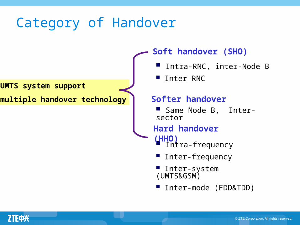
Category of Handover
Intra-RNC, inter-Node B Inter-RNC
Soft handover (SHO)
Same Node B, Inter-sector
Softer handover
Intra-frequency Inter-frequency Inter-system (UMTS&GSM) Inter-mode (FDD&TDD)
Hard handover (HHO)
UMTS system support
multiple handover technology

Handover Demonstration
Hard
Handover
Soft
Handover

A
B
C
A
B
C
A
B
C
A
B
C
A
B
C
A
B
C
Soft Handover/Softer Handover
Soft Handover
Soft-Softer Handover
Softer Handover

Hard Handover
During the hard handover procedure, all the old radio links with the UE are abandoned before new ones are established, so there must be service interruption during the HHO.
Hard handover may occur in the following main cases
When the UE is handed over to another UTRAN carrier, or another technology mode.
When soft handover is not permitted (if O&M constraint)
Hard Handover
Node B
SRNCRNC or BSC
CN
Node B or BTS

Soft/Softer Handover
The soft/softer handover allows to migrate from one cell to another without service interruption or without deleting all old radio links.
UE can connect to more than one cell simultaneously and take benefit from the macro-diversity.
Soft Handover Softer Handover
CN CN
Iur
The two Node Bs may belong to the
same RNC
The two Node Bs may belong to the Same RNC
Soft Handover Softer Handover
SRNC DRNC
CN
Node B
SRNC
CN
Soft Handover Softer Handover
Node B
CN

UMTS General Handover Trilogy
Measurement Control UTRAN demands the UE to start measurement through
issuing a measurement control message.
Handover decision UTRAN makes the decision based on the measurement
reports from UE. The implementation of handover decision is various for different vendors. It impacts on the system performance critically.
Handover execution UTRAN and UE execute different handover procedure
according to the handover command.

(A) RNC sends measurement control message to UE (Measurement Control)
(B) UE starts measurement task with the parameters included in the message, and reports measurement results ( Measurement Report)
(C) RNC stores the measurement results according to frequencies and cells
(D) RNC Estimates the quality of each carrier (including intra-frequency and inter-frequency)
(E) Quality
Decision
(G) Allocate resource in target cell, prepare to execute handover
(F) maintain the active set and monitored set
(H) Allocate resource in target cell, prepare to execute handover
Current carrier has good quality
Other system has good quality
Other carrier has good quality
( I ) If handover is required, RNC sends handover command with target cell to UE
Handover Flows
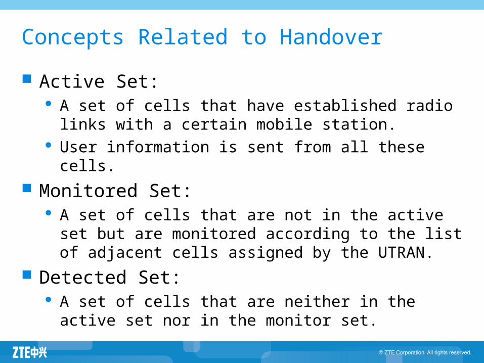
Concepts Related to Handover
Active Set: A set of cells that have established radio links with a
certain mobile station. User information is sent from all these cells.
Monitored Set: A set of cells that are not in the active set but are
monitored according to the list of adjacent cells assigned by the UTRAN.
Detected Set: A set of cells that are neither in the active set nor in the
monitor set.

Soft handover event
Event Description
1AQuality of target cell improves, entering a report range of relatively activating set quality
1BQuality of target cell decreases, depart from a report range of relatively activating set quality
1CThe quality of a non-activated set cell is better than that of a certain activated set cell
1D Best cell generates change
1EQuality of target cell improves, better than an absolute threshold
1FQuality of target cell decreases, worse than an absolute threshold

An Example of SHO Procedure
Pilot Ec/Io of cell 1
time
PilotEc/Io
Connect to cell1 Event 1A Event 1C Event 1B ( add cell2 )( replace cell1 with cell 3 )( remove cell3 )
Pilot Ec/Io of cell 2
Pilot Ec/Io of cell 3
⊿ t ⊿ t ⊿ t

Content
Classification of channels Physical layer procedure RAKE Receiver Handover Control Admission Control Load Control

Admission Control
The admission control is employed to admit the access of incoming call. Its general principal is based on the availability and utilization of the system resources.
If the system has enough resources such as load margin, code, and channel element etc. the admission control will accept the call and allocate resources to it.

Purpose of Admission Control
When user initiates a call , the admission control should implement admission or rejection for this service according to the resource situation.
The admission control will sustain the system stability firstly and try the best to satisfy the new calling service’s QoS request, such as service rate, quality (SIR or BER), and delay etc. basing on the radio measurement.
Admission control is the only access entry for the incoming services, its strategy will directly effect the cell capacity and stability, e.g. call loss rate, call drop rate.

Admission Control in Uplink
Itotal_old+ΔI >Ithreshold
The current RTWP (Received Total Wide Power) value of cell, which is reported by Node B
AccessThreshold
Interference capacityService priorityReserved capacity for handover
Iown-cell
0~N
Iother-cell
The forecasted interference including the delta interference brought by the incoming service is calculated by the admission algorithm, and its result depends on the QoS and transmission propagation environment

Admission Control in Downlink
Ptotal_old+△P>=Pthreshold Access Threshold
The forecasted TCP value including delta power required for the incoming service is calculated by the admission algorithm, and its result depends on the QoS and transmission propagation environment.
The current TCP value of cell, which is reported by Node B( Transmitted Carrier Power*Pmax )
Max TCP of cellService priorityReserved capacity for handover

Content
Classification of channels Physical layer procedure RAKE Receiver Handover Control Admission Control Load Control

Load control
The purpose of load control is to keep the
system load under a pre-planned threshold
through several means of decreasing it, so as to
improve the system stability.
The speed and position
changing of UE may
worsen the wireless
environment.
Increased transmitted
power will increase the
system load.
Purpose of Load Control
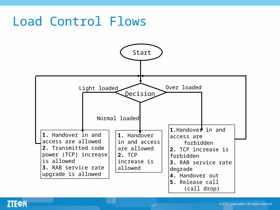
Load Control Flows
Start
DecisionLight loaded Over loaded
Normal loaded
1.Handover in andaccess are forbidden2. TCP increase isforbidden3. RAB service ratedegrade4. Handover out5. Release call (call drop)
1. Handover in and access are allowed2. Transmitted code power (TCP) increase is allowed3. RAB service rate upgrade is allowed
1. Handover in and access are allowed2. TCP increase is allowed

Load Control in Uplink
Triggers RTWP (Received Total Wide-band Power) value from
measurement report exceeds the uplink overload threshold; Admission control is triggered when rejecting the access of
services with lower priority due to insufficient load capacity in uplink.
Methods for decreasing load Decrease the target Eb/No of service in uplink; Decrease the rate of none real time data service; Handover to GSM system; Decrease the rate of real time service, e.g. voice call; Release calls.
Methods for increasing load Increase the service rate.

Load Control in Downlink
Triggers TCP (Transmitted Carrier Power) value from measurement report
exceeds the downlink overload threshold; Admission control is triggered when rejecting the access of
services with lower priority due to insufficient load capacity in downlink.
Methods for decreasing load Decrease the downlink target Eb/No of service in downlink; Decrease the rate of none real time data service; Handover to coverage-shared light loaded carrier; Handover to GSM system; Decrease the rate of real time service, e.g. voice call; Release calls.
Methods for increasing load Increase the service rate.
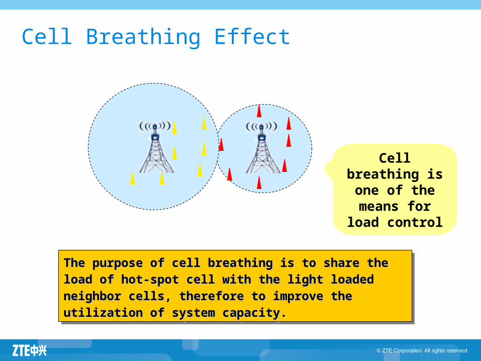
Cell breathing is one of the means for load control
The purpose of cell breathing is to share the load of hot-The purpose of cell breathing is to share the load of hot-
spot cell with the light loaded neighbor cells, therefore to spot cell with the light loaded neighbor cells, therefore to
improve the utilization of system capacity.improve the utilization of system capacity.
Cell Breathing Effect

Example for load control
Cell Breathing EffectCell Breathing Effect With the increase of activated
terminals and the increase of high
speed services, interference will
increase. The cell coverage area will shrink. Coverage blind spot occurs Drop of call will happen at the edge
of cell
Coverage and
capacity are
interrelated

DL/UL: Add carrier six sectors
DL/UL: Add carrier six sectors
UL Tower Mounted Amplifier (TMA) 4 Rx Div OTSR
UL Tower Mounted Amplifier (TMA) 4 Rx Div OTSR
DL transmission diversity (Tx Div) high power amplifier
DL transmission diversity (Tx Div) high power amplifier
Add basestation
“last choice”
Add basestation
“last choice”
Optimization methods
To overcome Cell Breathing Effect caused by increased traffic and meet different requirements for capacity and coverage in different environment, following solutions can be applied:

Factors Impact on UMTS capacity
RAKE Receiver
The advanced receiving and baseband processing technology is introduced to overcome the fast fading
Power Control Reducing interference, saving power and Increasing capacity
Handover Control
Impacting the capacity through applying different proportion and algorithm of soft handover
Admission Control
Admitting a connection base on the load and the admission threshold of planned capacity
Load Control Monitoring system load and adjusting the ongoing services to avoid overload
OVSF Code The Allocation of codes impacts the maximum number of simultaneous connections.
Wireless Environment
Wireless environment such as interferences, UE position and mobility etc. can influent the cell capacity
Factors affects UMTS Capacity