1 © 2006 nokia acoustical measurements.ppt / 2006-04-19 / ij acoustical measurements iiro jantunen...
TRANSCRIPT

1 © 2006 Nokia Acoustical measurements.ppt / 2006-04-19 / IJ
Acoustical measurements
Iiro Jantunen
Nokia Research Center
19.4.2006
S-108.4010 Licentiate course in measurement science and technology

2 © 2006 Nokia Acoustical measurements.ppt / 2006-04-19 / IJ
Contents
•Principles of acoustics•Acoustics measurements •Microphone•Sound pressure level measurements
•Sound intensity measurements
•Calibration•SoundField

3 © 2006 Nokia Acoustical measurements.ppt / 2006-04-19 / IJ
Principles of acoustics
•Sound waves in gas or liquid
•No shear forces
→ no transverse waves
→ purely longitudinal waves
•Audible sound range 20 Hz – 20 kHz
•Fully described by 3 variables
•Pressure
•Particle velocity
•Density

4 © 2006 Nokia Acoustical measurements.ppt / 2006-04-19 / IJ
Wave equations of sound
•Euler’s equation• Newton’s 2nd law (F=ma)
applied to fluid
•Continuity equation• Bringing extra air to a
volume increases density
•State equation• Relates pressure changes
to density

5 © 2006 Nokia Acoustical measurements.ppt / 2006-04-19 / IJ
Wave equation of sound
•Previous wave equations used pressure, density and particle velocity
•Eliminating density and particle velocity the wave equation of sound is obtained
•Two basic solutions:
•Plane wave
•Spherical wave

6 © 2006 Nokia Acoustical measurements.ppt / 2006-04-19 / IJ
Free field acoustics
•Sound propagates to all directions without diffraction, reflection or absorption
•Spherical waves•In principle, infinite, empty space without reflections
•In practice, anechoic chamber, with near 100% absorptive walls

7 © 2006 Nokia Acoustical measurements.ppt / 2006-04-19 / IJ
Free field microphone
• Intended to measure the sound pressure as it existed before the microphone was introduced
• Microphone pointed to source• Microphone tip causes an
increase in sound pressure• Taken care of by internal
acoustical damping to achieve flat frequency response
8 © 2006 Nokia Acoustical measurements.ppt / 2006-04-19 / IJ
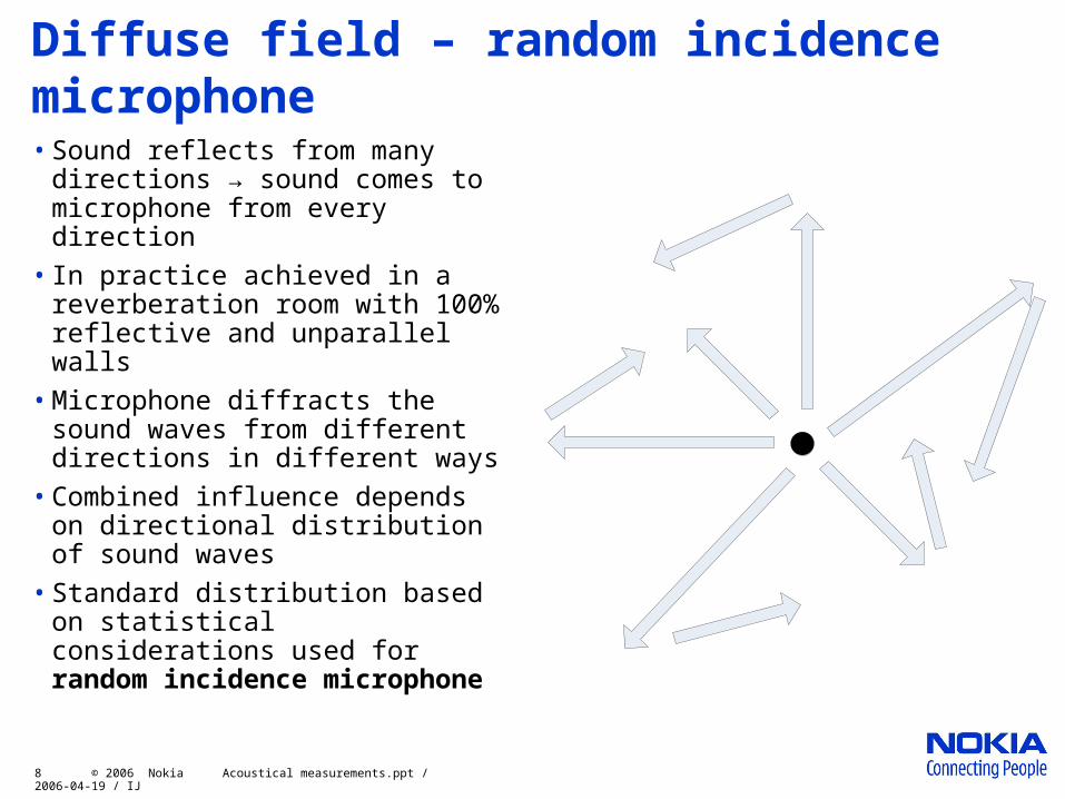
Diffuse field – random incidence microphone• Sound reflects from many
directions → sound comes to microphone from every direction
• In practice achieved in a reverberation room with 100% reflective and unparallel walls
• Microphone diffracts the sound waves from different directions in different ways
• Combined influence depends on directional distribution of sound waves
• Standard distribution based on statistical considerations used for random incidence microphone
9 © 2006 Nokia Acoustical measurements.ppt / 2006-04-19 / IJ
Closed coupler
•Chamber with small dimensions compared to sound wavelength
•Special case: standing wave tube
• Diameter smaller than sound wavelength
• Source at the end
• Possible to calculate the sound field
• Used in calibration
•Used in microphone calibration
10 © 2006 Nokia Acoustical measurements.ppt / 2006-04-19 / IJ
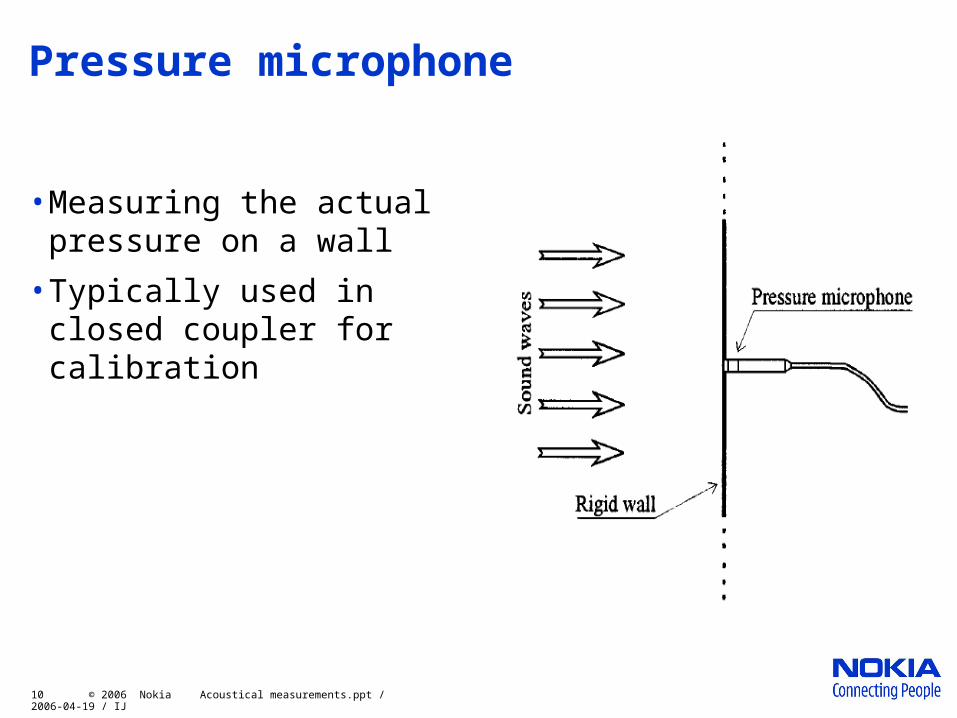
Pressure microphone
•Measuring the actual pressure on a wall
•Typically used in closed coupler for calibration

11 © 2006 Nokia Acoustical measurements.ppt / 2006-04-19 / IJ
Microphone directionality
•Directionality indicates the sensitiveness of a microphone to sound coming from different directions
•No microphone is perfectly omnidirectional•Cardioid or hypercardioid commonly used to record vocals•Most ribbon microphones are bi-directional•Shotgun directionality used outdoors for TV/film production and wildlife recordings

12 © 2006 Nokia Acoustical measurements.ppt / 2006-04-19 / IJ
Parabolic microphone
•Parabolic reflector used to collect sound waves to microphone
•Very directional
•For eavesdropping in e.g. spying

13 © 2006 Nokia Acoustical measurements.ppt / 2006-04-19 / IJ
Microphone transducers
•Condenser microphones
•Electret capacitor microphones
•Dynamic microphones
•Ribbon microphones
•Carbon microphones
•Piezoelectric microphones
•Laser microphones

14 © 2006 Nokia Acoustical measurements.ppt / 2006-04-19 / IJ
Condenser microphone
•Diaphragm and backplate form a plate capacitor
•Charge kept constant → voltage varies as pressure actuates the diaphragm
•External voltage supply or pre-charged diaphragm
•Acoustical performance determined by physical dimensions
15 © 2006 Nokia Acoustical measurements.ppt / 2006-04-19 / IJ
Condenser microphone – cont
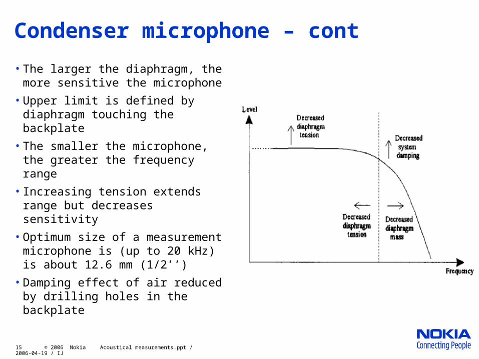
• The larger the diaphragm, the more sensitive the microphone
• Upper limit is defined by diaphragm touching the backplate
• The smaller the microphone, the greater the frequency range
• Increasing tension extends range but decreases sensitivity
• Optimum size of a measurement microphone is (up to 20 kHz) is about 12.6 mm (1/2’’)
• Damping effect of air reduced by drilling holes in the backplate

16 © 2006 Nokia Acoustical measurements.ppt / 2006-04-19 / IJ
Electret microphone
• Invented at Bell Labs in 1962 by Gerhard Sessler and Jim West
• Diaphragm permanently polarized the same way as permanent magnets magnetized (electrostatic magnet)
• Once considered low price and low quality
• Now most common microphone type

17 © 2006 Nokia Acoustical measurements.ppt / 2006-04-19 / IJ
Dynamic microphone
• A movable coil is attached to the diaphragm
• An unmovable magnet produces a magnetic field
• Moving diaphragm moves the coil in the magnetic field, inducing a measurable current
• Exactly same principle as in loudspeakers, only reversed
• Poor low-frequency response → reduces handling noise
• Robust, relatively inexpensive and resistant to moisture→ widely used on-stage

18 © 2006 Nokia Acoustical measurements.ppt / 2006-04-19 / IJ
Ribbon microphones
• Revolutionized recording and broadcast industry in the 30’s
• Special type of dynamic microphones
• Thin metal ribbon between poles of magnet
• Voltage output typically low compared to normal dynamic microphones
• Bidirectional
• Very sensitive and accurate
• Generally delicate and expensive

19 © 2006 Nokia Acoustical measurements.ppt / 2006-04-19 / IJ
Carbon microphones
• Invented by David Hughes in 1878
• Very important in the history of telephone
• Sound pressure (AP) presses the diaphragm (2) to a bed of carbon granules (1). Contact resistance depends on the pressure → resitance R changes
• Also an amplifier
• Extremely low-quality sound reproduction
• Very limited frequency range
• Very robust

20 © 2006 Nokia Acoustical measurements.ppt / 2006-04-19 / IJ
Piezo microphones
• Piezoelectric material
• Diaphragm moves the armature to bend piezoelectric crystal over a fulcrum
• Small size, cheap, low quality
• Have replaced carbon microphones
• Often used as
• contact microphones to sound instruments
• underwater or other unusual environments
21 © 2006 Nokia Acoustical measurements.ppt / 2006-04-19 / IJ
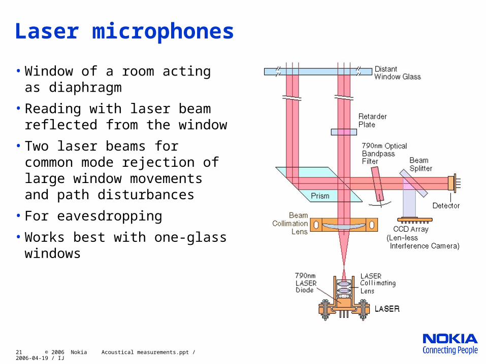
Laser microphones
• Window of a room acting as diaphragm
• Reading with laser beam reflected from the window
• Two laser beams for common mode rejection of large window movements and path disturbances
• For eavesdropping
• Works best with one-glass windows

22 © 2006 Nokia Acoustical measurements.ppt / 2006-04-19 / IJ
Sound level measurements
•Measurement of sound pressure filtered by
•frequency (A-weighting)
•time-domain (RMS)
•Mimics response of human ear to noise

23 © 2006 Nokia Acoustical measurements.ppt / 2006-04-19 / IJ
Human hearing frequency response
A-weighting curveFor subjective responses in special cases there are B-, C- and D-weighting curves•very high or low level•special noise, e.g., of aircraft

24 © 2006 Nokia Acoustical measurements.ppt / 2006-04-19 / IJ
Sound level measurements
•IEC International Standard 651 ”Sound Level Meters”
•Tolerances per frequency band defined for 4 classes of accuracy
•Type 0: precision laboratory use
•Type 1: general purpose
•Type 2: low price
•Type 3: not used in practice (too wide tolerances)

25 © 2006 Nokia Acoustical measurements.ppt / 2006-04-19 / IJ
Sound intensity measurements
no. x/r y/r z/r
1 -0.99 0 0.15
2 0.5 -0.86 0.15
3 0.5 0.86 0.15
4 -0.45 0.77 0.45
5 -0.45 -0.77 0.45
6 0.89 0 0.45
7 0.33 0.57 0.75
8 -0.66 0 0.75
9 0.33 -0.57 0.75
10 0 0 1.00
ISO Standard 3745 “Acoustics — Determination of sound power levels of noise sources — Precision method for anechoic and semi-anechoic rooms”

26 © 2006 Nokia Acoustical measurements.ppt / 2006-04-19 / IJ
Two-microphone probe
• Measures the sound intensity in two directions
• Pressure is mean of the two measured pressures
• Air particle velocity calculated from the two pressures
• All intensity is in radial direction, no intensity in perpendicular
• Powerful tool to locate noise sources

27 © 2006 Nokia Acoustical measurements.ppt / 2006-04-19 / IJ
Calibration techniques
•Reciprocity calibration method
•Comparison or substitution methods
•Pistonphone (closed coupler)
•Sound pressure calibrator
•Electrostatic actuation

28 © 2006 Nokia Acoustical measurements.ppt / 2006-04-19 / IJ
Reciprocity calibration method
•Microphone can be used as a loudspeaker
•Three test microphones measured against each other alternating the function
•As a result a set of 3 equations with microphone sensitivities as unknowns
•Very accurate
•Rather tedious
•Requires well-controlled environment
•Seldom used in practical situations

29 © 2006 Nokia Acoustical measurements.ppt / 2006-04-19 / IJ
Comparison/substitution methods
•Microphone measured related to a reference microphone
•Comparison method: microphone and reference at the same time
•Substitution method: microphone put in the lace of the reference
•Sound source stability

30 © 2006 Nokia Acoustical measurements.ppt / 2006-04-19 / IJ
Pistonphone
•Closed coupler
•Well-defined sound pressure level
•Relatively simple mechanically, very stable
•Used often as the sound source in comparison/subsitution calibration
•Accuracy around 0.1 dB
•Depends on• Volume of the coupler
• Volume displacement
• Barometric pressure
• Humidity
• Heat dissipation

31 © 2006 Nokia Acoustical measurements.ppt / 2006-04-19 / IJ
Sound pressure calibrator
•Small, self-contained
•Comparison calibrator
•Closed coupler
•Small loudspeaker produces single-frequency signal
•Reference microphone gives feedback signal
•Well-defined, provided that reference microphone and feedback gain are stable
•For field-calibration of microphones
•Normally not for laboratory calibrations
32 © 2006 Nokia Acoustical measurements.ppt / 2006-04-19 / IJ
Electrostatic calibration
•Direct use of electrostatic actuator to drive the diaphragm
•800 V DC
•50-150 V AC signal
•Generally used to measure frequency response of microphones
•Widely used as a convenient and accurate test method
•For production and final calibration of measurement microphones

33 © 2006 Nokia Acoustical measurements.ppt / 2006-04-19 / IJ
SoundField microphone
• 3D view of the sound with a single device
• 4-channel measurement of sound: B-format
• The spatial pattern can be decided later
• Mono, stereo, 5.1, …
• Fairly expensive, but replaces effectively a system of many microphones
• http://www.soundfield.com