1-2beam pumping system_4
DESCRIPTION
BEAM PUMPING SYSTEMTRANSCRIPT

BEAM PUMPING UNITS BEAM PUMPING UNITS

The Beam Pumping units (pumpjack or surface pumping unit) is used to stroke the bottom hole
pump up and down so that it will pump reservoir fluids to surface
This is accomplished by converting rotary motion to reciprocating vertical motion.
Rotary power is supplied to a gearbox by an
electric motor or gas engine.
The gearbox uses a series of gears to convert
this high speed power to low speed power. (Usually a ratio of approximately 30 to 1 on a
double reduction unit.)

the gearbox turns the cranks and the cranks lift the pitman arms up and down (rotary to reciprocating).
The pitman arms move the walking beam up and down consequently the horses head on the opposite
end of the walking beam has to go up and down.
This action causes the bridle cable to move the carrier bar up and down which in turn moves the sucker rod system up and down and consequently
the traveling valve which connect to plunger.
Pumping units Components


The smallest API jack has a gearbox that can
handle 6400 inch pounds of torque. It is a structure that can handle 3200 pounds polish
rod load and has a maximum stroke length of 16".
The API designation of this jack is 64-3.2-16.

On the other end of the scale, the largest unit On the other end of the scale, the largest unit
has a 3,648,000 inch pound gearbox, can has a 3,648,000 inch pound gearbox, can
handle 47,000 pound load and has a 300" handle 47,000 pound load and has a 300"
maximum stroke length! maximum stroke length!
The API designation of this jack is 3648The API designation of this jack is 3648--470470--
300. 300.

PUMPING UNIT DESIGNATIONSPUMPING UNIT DESIGNATIONS

PUMPJACK CONFIGURATION

There are numerous There are numerous
pumping unit configurations pumping unit configurations
�� A A -- Air BalanceAir Balance
�� B B -- Beam BalanceBeam Balance
�� C C -- ConventionalConventional
�� M M -- Mark IIMark II
�� LP LP -- Low Profile Low Profile
�� RM RM -- Reverse Mark Reverse Mark
�� CM CM -- Conventional PortableConventional Portable

The "Conventional" unit has the sampson post
in the middle and is the most common jack configuration
Conventional unit


Conventional Pumping unitConventional Pumping unit
�� The classical Conventional geometry is organized so that The classical Conventional geometry is organized so that when the walking beam is horizontalwhen the walking beam is horizontal, the , the equalizer equalizer bearingbearing lies directly over the lies directly over the center of the crankshaft. center of the crankshaft.
�� As a direct result of this arrangement, the As a direct result of this arrangement, the upstroke upstroke occurs in approximately 180occurs in approximately 180°°of crank rotation, and the of crank rotation, and the downstrokedownstroke occurs in the remaining 180occurs in the remaining 180°°of crank of crank rotation. rotation.
�� This geometry is truly a byThis geometry is truly a by--directional machine. That is, directional machine. That is, its its performance in both the clockwise and counter performance in both the clockwise and counter clockwiseclockwise rotation is approximately the rotation is approximately the same.same.

Conventional pumping unit Conventional pumping unit
( class one)( class one)

Some of conventional pumping Some of conventional pumping
units configurationsunits configurations

Mark II pumping unitMark II pumping unit
Mark II" has the Sampson post at the back of Mark II" has the Sampson post at the back of
the unit and the gearbox in the middle. the unit and the gearbox in the middle.


Mark II pumping unitMark II pumping unit
The advantage is that the rods are The advantage is that the rods are travellingtravellingslower on the upstroke than on the slower on the upstroke than on the downstrokedownstroke so torque is more even.so torque is more even.
This speed variance is good in light oil or This speed variance is good in light oil or high high watercutwatercut shallow wells but in heavier shallow wells but in heavier viscosity wells, the rods hang up more viscosity wells, the rods hang up more easily. Higher torque can result. easily. Higher torque can result.

�� The Mark II pumping unit is a The Mark II pumping unit is a class three leverclass three leversystem, system,
�� It is differs from a Conventional geometry in that the It is differs from a Conventional geometry in that the walking beam pivots off of the rear end of the beam walking beam pivots off of the rear end of the beam rather than about the center of the beam as does a rather than about the center of the beam as does a Conventional unit. Conventional unit.
�� Mark II geometry lifts the well through a pitman Mark II geometry lifts the well through a pitman arrangement that pushes up on the front end of the arrangement that pushes up on the front end of the walking beam as apposed to the Conventional walking beam as apposed to the Conventional pitman, which pulls down on the rear end of the pitman, which pulls down on the rear end of the walking beam.walking beam.
Mark II Pumping UnitsMark II Pumping Units

why the Mark II generally has lower why the Mark II generally has lower
polished rod loads than the polished rod loads than the
Conventional unit.Conventional unit.
�� The characteristics of the Mark II geometry The characteristics of the Mark II geometry
cause the polish rod to begin the upstroke cause the polish rod to begin the upstroke
portion of the cycle at a low acceleration and portion of the cycle at a low acceleration and
come down off the top of the stroke at a come down off the top of the stroke at a
higher acceleration. higher acceleration.
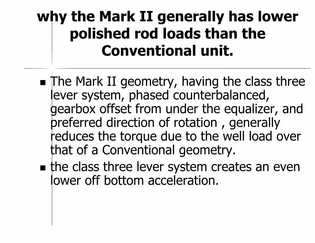
�� The Mark II geometry, having the class three The Mark II geometry, having the class three lever system, phased counterbalanced, lever system, phased counterbalanced, gearbox offset from under the equalizer, and gearbox offset from under the equalizer, and preferred direction of rotation , generally preferred direction of rotation , generally reduces the torque due to the well load over reduces the torque due to the well load over that of a Conventional geometry. that of a Conventional geometry.
�� the class three lever system creates an even the class three lever system creates an even lower off bottom acceleration. lower off bottom acceleration.
why the Mark II generally has lower why the Mark II generally has lower
polished rod loads than the polished rod loads than the
Conventional unit.Conventional unit.

• Placing the equalizer between the horsehead and the Samson post creates a “push-up” or “Class 3”lever system.
• The 195°upstroke, coupled with the front mounted geometry, reduces the acceleration at the beginning of the upstroke where the load is greatest, thereby effecting a reduction in polished rod load.

Air Balanced UnitsAir Balanced Units


Air Balanced UnitsAir Balanced Units
�� counterbalance can be achieved using an air counterbalance can be achieved using an air cylinder instead of metal counterweights. cylinder instead of metal counterweights.
�� This configuration requires an air compressor This configuration requires an air compressor to maintain proper air pressure for correct to maintain proper air pressure for correct counterbalance. counterbalance.
�� Maintenance is always higher on machinery Maintenance is always higher on machinery (compressors, air seals, etc.) than on pieces (compressors, air seals, etc.) than on pieces of steel (like counterweights).of steel (like counterweights).
Air Balanced UnitsAir Balanced Units
�� it is easier to adjust the air pressure for it is easier to adjust the air pressure for balancing a jack than it is to move balancing a jack than it is to move counterweights on a conventional unit.counterweights on a conventional unit.
�� Care must be taken to ensure that no Care must be taken to ensure that no hydrocarbons enter the air cylinder because hydrocarbons enter the air cylinder because an explosive mixture can result. an explosive mixture can result.
�� The air compressor suction point should The air compressor suction point should therefore be located at a point which therefore be located at a point which prevents this.prevents this.

AIR BALANCEDAIR BALANCED

�� it is also a class three lever system, it is also a class three lever system,
�� It differs from the Mark II in the method of It differs from the Mark II in the method of counterbalance. counterbalance.

Air Balance unitAir Balance unit
�� The Air Balance unit is the only beam The Air Balance unit is the only beam pumping unit which lends itself to automatic pumping unit which lends itself to automatic counterbalance. counterbalance.
�� There is available today an electronic "Black There is available today an electronic "Black Box" which is capable of sensing torque Box" which is capable of sensing torque unbalance.unbalance.
�� The electronics correct that situation by The electronics correct that situation by turning on an air compressor to increase the turning on an air compressor to increase the air pressure in the air system or open a air pressure in the air system or open a solenoid valve to decrease the air pressure solenoid valve to decrease the air pressure in the air tank, thus, adjusting the in the air tank, thus, adjusting the counterbalance to an optimum.counterbalance to an optimum.

�� The biggest disadvantageThe biggest disadvantage of the Air Balance of the Air Balance
pumping unit is that it required routine pumping unit is that it required routine
proper maintenance. proper maintenance.
�� The Air Balance method of counterbalance The Air Balance method of counterbalance
permits the manufacture of the worlds permits the manufacture of the worlds
largest beam and sucker rod pumping unit largest beam and sucker rod pumping unit
in the Air Balance Ain the Air Balance A--25602560--470470--240.240.

Beam Balanced Pumping Beam Balanced Pumping
Unit Unit

Beam Balanced Pumping Beam Balanced Pumping
UnitUnit
�� The counterweights are placed on The counterweights are placed on
the walking beam on this unit. the walking beam on this unit.
�� The largest beam balance unit is a The largest beam balance unit is a
5757--109109--48 so it is used on shallow 48 so it is used on shallow
low productivity wells low productivity wells

Low Profile pumping unit Low Profile pumping unit

CONVENTIONAL PORTABLECONVENTIONAL PORTABLE

�� is an entirely self contained pumping is an entirely self contained pumping
unit, mounted on its own integral unit, mounted on its own integral
trailer trailer
�� These units are available in sizes These units are available in sizes
varying from a CMvarying from a CM--160D160D--173173--74 74
through a CMthrough a CM--456D456D--305305--120.120.
CONVENTIONAL PORTABLECONVENTIONAL PORTABLE

STRUCTURESSTRUCTURES
For the purpose of the following discussion, we will divide the beam
pumping unit into the structural components and the gearbox
components.
The structural components are, in general, made up of
•horsehead,
•walking beam,
•samson post,
• equalizer,
•pitmans,
•unit base, and
•prime mover base.

HorseheadHorsehead

•The function of the horsehead, is to allow the pumping unit to
pull the polished rod vertically through the center of the well
head
•There are a number of ways of attaching the horsehead to the
walking beam .
• As an additional safety feature, most pumping unit
manufactures provide a safety bar that also attaches the
horsehead to the walking beam.
•The safety bar prevents the horsehead from falling off the
walking beam during those instances when the well load is not
attached to the horsehead or during a high rod part that could
throw the horsehead off the walking beam and perhaps injure
someone.
HorseheadHorsehead

CRANK PIN BEARING CRANK PIN BEARING
ASSEMBLYASSEMBLY

crank pin bearing assembly
a crank pin bearing assembly is made up of a
•tapered crank pin,
•bearing housing and seal,
•a double row spherical bearing

•The crank pin is tapered so that it can be fit into a
matching taper on the crank to allow for a fit between the crank and the pin that is both tight and, yet, relatively easy to disassemble to allow for stroke changing.
• It is extremely important that the taper on the crank pin as well as the taper in the crank be the same

equalizer bearing assembly equalizer bearing assembly
componentscomponents

equalizer bearing assembly equalizer bearing assembly
components components

Center Bearing For a Center Bearing For a
Conventional Pumping Unit Conventional Pumping Unit

GEAR TRANSMISSIONGEAR TRANSMISSION

•It is the more complex and vital parts of the pumping unit is the gear transmission.
•Because of its complexity, the transmission represents approximately 50% of the manufacturing cost of the pumping unit.
•The purpose of a gear reduction unit is to both reduce the speed of the prime mover to the desired pumping speed


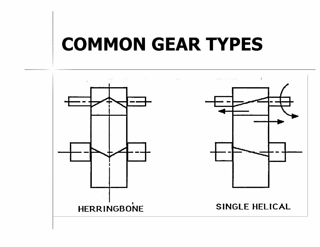
COMMON GEAR TYPESCOMMON GEAR TYPES

•The gearing used in pumping units is divided into two types. For the larger gearing (40 API rating and larger), the herringbone gear design dominates. The smaller, less
expensive, lighter duty pumping unit usually uses the single helical design

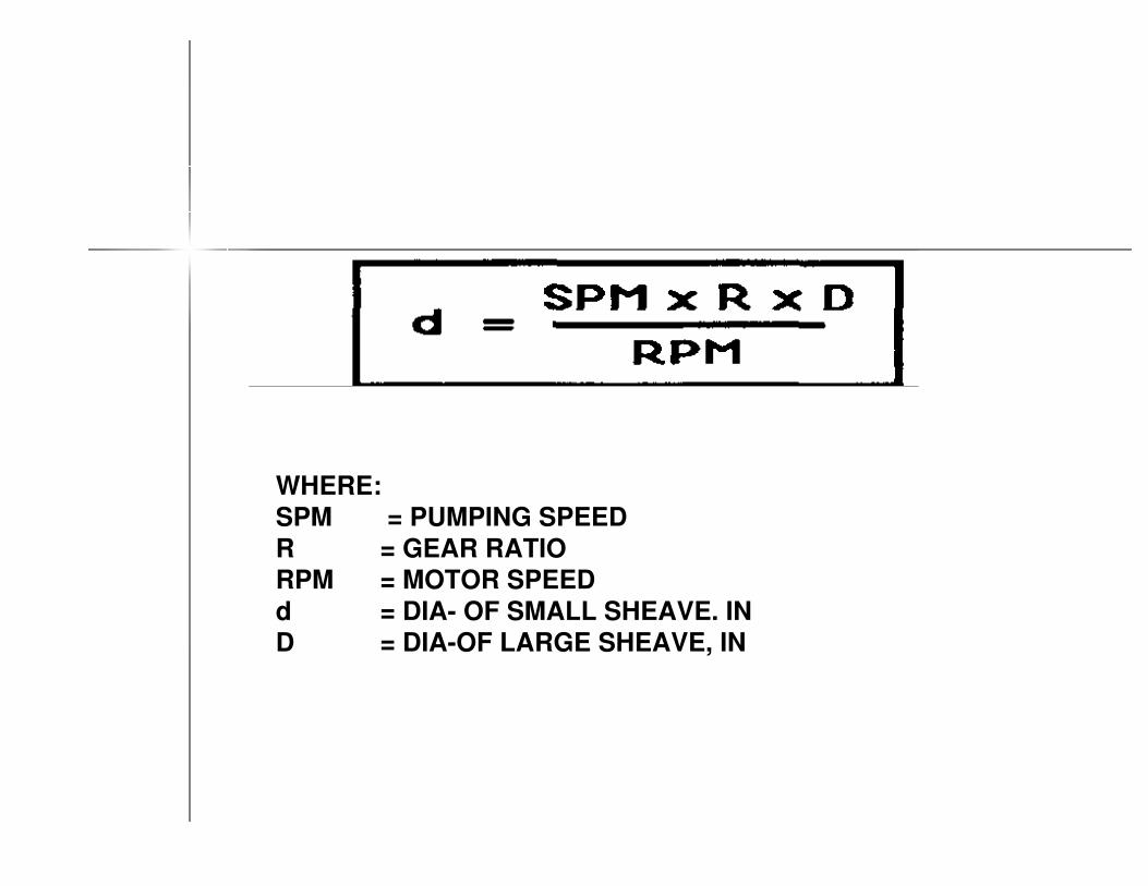
WHERE:
SPM = PUMPING SPEED
R = GEAR RATIO
RPM = MOTOR SPEED
d = DIA- OF SMALL SHEAVE. IN
D = DIA-OF LARGE SHEAVE, IN
TORQUETORQUE
�� Torque is expressed as "distance x force" and Torque is expressed as "distance x force" and the accepted units for gearbox torque are the accepted units for gearbox torque are inch pounds. inch pounds.
�� In other words, the torque on a given In other words, the torque on a given gearbox will be the result of what forces the gearbox will be the result of what forces the crank arm sees multiplied by the length of crank arm sees multiplied by the length of the force arms doing the work.the force arms doing the work.
�� ..

TORQUETORQUE
�� The gearbox torque consists of The gearbox torque consists of
two components. two components.
–– One is the force created by the One is the force created by the
well load andwell load and
–– the other is the force created by the other is the force created by
the counterweights, crank arms the counterweights, crank arms
and unit imbalanceand unit imbalance

By formula Torque can By formula Torque can
be expressed as be expressed as
Gear box torque = well load Gear box torque = well load
torque torque -- counterbalance counterbalance
torquetorque
TORQUETORQUE

Unit loading and gearbox torque will be Unit loading and gearbox torque will be
altered as a result of any of the following altered as a result of any of the following
condition changes:condition changes:
�� Bottom hole pump size.Bottom hole pump size.
�� Unit speed (SPM).Unit speed (SPM).
�� Counterbalance adjustment.Counterbalance adjustment.
�� Fluid level (Fluid level (downholedownhole).).
�� Flow line pressure.Flow line pressure.
�� Unit stroke length.Unit stroke length.
TORQUETORQUE

GEAR BOX TORQUEGEAR BOX TORQUE
�� Gearbox torque is the Gearbox torque is the
instantaneous torque for a given instantaneous torque for a given
crank angle displayed in crank angle displayed in
thousands of inch pounds. thousands of inch pounds.
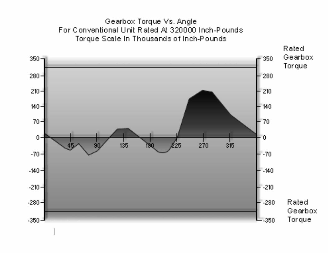

* Indicates Maximum Torque.* Indicates Maximum Torque.
18752187527833778337--6067260672195.0195.0
18349183494182741827--5646556465210.0210.0
1956419564320343203417831783225.0225.0
204752047527579275798028080280240.0240.0
21404214042521425214168552168552255.0255.0
20799207992389523895186875186875* 270.0* 270.0
19917199172319223192178194178194285.0285.0
18518185182298822988138266138266300.0300.0
17484174842348023480109922109922315.0315.0
167771677725546255468780387803330.0330.0
162701627033417334176073060730345.0345.0
154911549120890220890222947229470.00.0
Actual LoadActual LoadPermissible Permissible
LoadLoadTorqueTorqueCrank AngleCrank Angle
UPSTROKEUPSTROKE
Torque Calculations for Conventional Unit Counterbalance Effect Torque Calculations for Conventional Unit Counterbalance Effect = =
17207 Pounds 17207 Pounds
Gear Box Rating of 320000 InchGear Box Rating of 320000 Inch--PoundsPounds

* Indicates Maximum Torque.* Indicates Maximum Torque.
1498814988--1045210452--107501075015.015.0
148301483013751375--363183631830.030.0
150591505950015001--493904939045.045.0
151881518869736973--280582805860.060.0
174311743183878387--7286572865*75.0*75.0
185681856894119411--558525585290.090.0
18456184569869986963046304105.0105.0
1843618436935593553933739337120.0120.0
1841918419717071704223542235135.0135.0
1869118691176417641511315113150.0150.0
1877418774--1278212782--1857318573165.0165.0
1877018770--121257121257--4786647866180.0180.0
Actual LoadActual LoadPermissible Permissible
LoadLoadTorqueTorqueCrank AngleCrank Angle
DOWNSTROKEDOWNSTROKE

Maximum Torque
When Counterbalanced 112714 112714
CBE Required toCounterbalance Unit 19133 19133
If the counterbalance effect is increased to 19 133 from 17 207 inch pounds then the unit would be in balance and the peak torque would be reduced to 112 714 inch
pounds.

، ، " " How fast can I run my How fast can I run my
pumping unitpumping unit ؟ ؟ ""
Since the pumping unit is connected to the polished rod through a flexible wire line, it cannot push the rods into the well. The limiting speed of the pumping unit is set by the fall of the rods into the well, and the fall of the rods into the well is set by the retarding forces in the well. Some of those forces are:
A. Friction from the stuffing boxB. Piston/Coupling effectC. Friction between the rods and the tubingD. Friction between the pump plunger and pump barrelE. Friction of fluid on the rods


PUMPJACK SIZE DETERMINATION

A pumping system has to be properly designed taking into consideration all the variables.
These variables include:
•Potential well productivity.•Well depth.
•Pump size.•Pumping speed.•Fluid viscosity.
•Sucker rod and tubing size etc