1 a cell/it li'ill! 'iec/ pilrl! . . .j s/id
TRANSCRIPT

2
1 A .l1u.<ir Cell/IT lI'ill! p, 'iec/ Pilrl! . .
.2 "Fin'u'affr" in a S/Id Bottle . ..
.J Prize Bridges of 1 !/69.
pagt .J
page 6
page 11,

MODERN STEEL CONSTRUCTION Published by
American Institute of Steel Construction 101 Park Avenue, New York, N. Y. 10011
OFFICERS
Eugene J. Pidgeon, President Edwin H. Webster, First Vice President Gilbert M. Dorland, Second Vice President William R. Jackson, Treasurer John K. Edmonds,
Executive Vice President Leslie H. Gillette,
Assistant Executive Vice President William W.lanigan
Secretary and General Counsel
EDITORIAL STAFF
Daniel Farb, Editor
Mary Anne Donohue, Asst. Edi tor
REGIONAL OFFICES
Atlanta, Georgia Birmingham, Alabama Boston, Massachusetts Chicago, Illinois Cleveland, Ohio Columbus, Ohio Dallas, Texas Denver, Colorado DetrOit, Michigan Charlotte, North Carolina Hartford, Connecticut Houston, Texas Los Angeles, California Memphis, Tennessee Milwaukee, Wisconsin Minneapolis, Minnesota New York, New York Oklahoma City, Oklahoma Omaha, Nebraska Philadelphia, Pennsylvania Pittsburgh, Pennsylvania St. Louis, Missouri San Francisco, California Seattle, Washington Syracuse, New York Washington, District of Columbia
VOLUME IX / NUMBER 3 / THIRD QUARTER 1969
CONTENTS
A Music Center with Perfect Pitch
"Firewater" in a Steel Bottle
Minges Coliseum
The Bridge Designer and Society
Prize Bridges of 1969
NEW AISC SPECIFICATION
3
6
8
13
14
A newly revised Specification for the Design, Fabrication and Erection of Structural Steel for Buildings was adopted by AISC on Febnlal'y 12, 1969. The "evisions, while not as fal'-reaching as the changes made in 1961, al'e considerably more extensive than those made in 1968. The most significant changes are:
o Addition of seven grades of steel and the elimination of three grades. Provisions are 'lOW included for steel grades having specified yield strengths from 36 ksi to 100 ksi 0 Updating of plastic design provisions to make the rllies applicable to steels liP to 65 ksi yield strel1gtlt 0 Expal1sion of plastic design "ules to ill elude braced multistory structures 0 Addition of provisions for design of hybrid beams and gil'del's 0 Recognition of composite design in negative moment a"eas 0 Addition of rules fOl' partial cOIILposite action 0 New nlle,~ to In'ovide safeguards against ponding of water on fiat roofs 0 Revi,~ion of rules of design fOl' fatigue loading 0 Increased working stresses for fillei welds 0 Clarifications of provisions in the 1969 Specification.
The new Specification prot'isions, fully justified on the basis of theory and testing, will result in desigl1s thai make more efficient use of steel in construction. Copies of the 1969 A ISC Specification and a Commenlary explaining the background of the provisions al'e available from AISC, 101 Park Avenue, New York, N . Y. 10017.
•
•

•
A MUSIC CENTER WITH PERFECT PITCH by W. C. Keene AISC Regional En gineer Cleveland, Oh io
THIRD QUARTER 1969
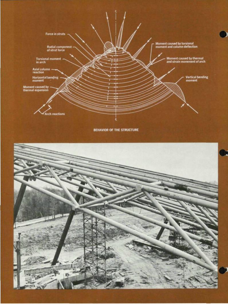
Appropriately, the Cleveland Orches· tra's ingenious summer home is musically inclined. A giant steel arch tilted 16· from the horizontal provides a unique solution to an acoustical challenge in the design of the Blossom Music Center near Akron. Ohio. The arch is the backbone for an intricate lacework and roof trusses. Its ends are anchored to a pair of enormous footings planted in the hillside. The arch is an all-welded box girder of trapezoidal cross section, and stiffened internally by structural
T's, fabricated of lY,-in. weathering steel plate. It is 7 ft wide at the bottom. 4 It wide at the top, with sloping sides and stretches 572 It between abutments. This enormous arch is supported in its inclined position by 10 tapered weathering steel columns, slanting outward from the curved member. Near the base of the arch, supported by six stubcolumns at the rear of the pavilion, a semicircular plate girder spans the quarter-circle seating area from one side of the arch to the other.

•
•
•
Between the semicircular plate girder and the arch a network of steel pipe trusses supports the fan·shaped, can· vex roof. The designers used pipe trusses because they have no flat sur· faces that might reflect or distort sound. The hall's curved sloping wall hangs within the line of columns sup· porting the arch, but does not touch them. It is supported by long·span trusses anchored to the underside of the arch and the wall foundation. The de· signers claim that the curved wall will provide enough acoustical surface below the arch to minimize the need for amplification equipment, but will also give the audience the sensation of being in an open air pavilion.
The music center is constructed over a natural amphitheater on a rolling countryside site. The facility contains column free seating for 4,600 under the roof and lawn seating for an additional 10,000 on the sloping hillside. There are dressing rooms and other prepara· tion areas beneath the stage and in a two·story, roof·terraced building built into a natural ravine behind the stage. The completed structure directs sound like a speaker horn to the audience in· side and out.
The music center was designed by architects Schafer, Flynn and Van Dijk, and the structural engineer was R. M. Gensert Associates, both of Cleveland, Ohio. The general contractor was Turner Construction Co., New York, N. Y. , with steel fabrication by Kilroy Steel Com· pany, Cleveland, and Tucker Steel Cor· poration of Knoxville, Tennessee.
Photos from Uncoln Arc Weldina Foundation
5
by Edward R. Stewart
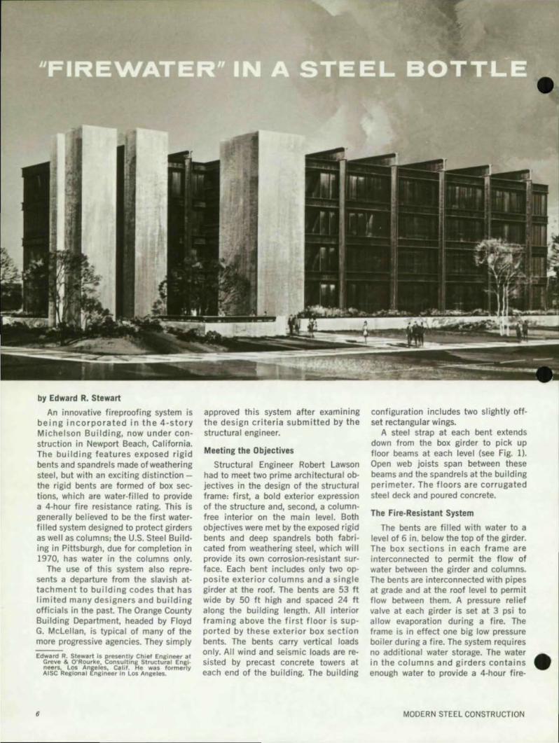
An innovative fireproofing system is being incorporated in the 4-story Michelson Building, now under can· struction in Newport Beach, California. The building features exposed rigid bents and spandrels made of weathering steel, but with an exciting distinctionthe rigid bents are formed of box sec· tions, which are water·filled to provide a 4·hour fire resistance rating. This is generally believed to be the first waterfilled system designed to protect girders as well as columns; the U.S. Steel Building in Pittsburgh, due for completion in 1970, has water in the columns only.
The use of this system also represents a departure from the slavish attachment to building codes that has limited many designers and building officials in the past. The Orange County Building Department, headed by Floyd G. McLellan, is typical of many of the more progressive agencies. They simply
Edward R. Stewart is presently Chief Enlineer at Greve & O'Rourke, Consulting Structural Enai · neers. los Angeles. Calif. He was formerly AISC Resional Engineer in Los Anseles.
6
•
approved this system after examining the design criteria submitted by the structural engineer.
Meeting the Objectives
Structural Engineer Robert Lawson had to meet two prime architectural objectives in the design of the structural frame: first, a bold exterior expression of the structure and, second, a columnfree interior on the main level. Both objectives were met by the exposed rigid bents and deep spandrels both fabricated from weathering steel, which will provide its own corrosion-resistant surface. Each bent includes only two opposite exterior columns and a single girder at the roof. The bents are 53 ft wide by 50 ft high and spaced 24 ft along the building length. All interior framing above the first floor is supported by these exterior box section bents. The bents carry vertical loads only. All wind and seismic loads are resisted by precast concrete towers at each end of the building. The building
configuration includes two slightly offset rectangular wings.
A steel strap at each bent extends down from the box girder to pick up floor beams at each level (see Fig. 1). Open web joists span between these beams and the spandrels at the building perimeter. The floors are corrugated steel deck and poured concrete.
The Fire-Resistant System
The bents are fi lied with water to a level of 6 in. below the top of the girder. The box sections in each frame are interconnected to permit the flow of water between the girder and columns. The bents are interconnected with pipes at grade and at the roof level to permit flow between them. A pressure relief valve at each girder is set at 3 psi to allow evaporation during a fire. The frame is in effect one big low pressure boiler during a fire. The system requires no additional water storage. The water • in the columns and girders contains enough water to provide a 4-hour fire-
MODERN STEEL CONSTRUCTION

•
•
•
resistance rating. This is well above the I-hour rating normally required by the code. The additional 3 hours of fireresistance did not raise the cost of the system, since the water-capacity of the girders and columns was dictated by the structural requirements.
The object of this fireproofing system, as in any such system, is to keep the surface temperature of the members low enough to maintain their full strength. During a fire, a water-filled member will be cool relative to the fire temperature. Secause of this low temperature, the member will absorb heat from the fire. Heat absorbed into the water-filled member during a fire will not raise the temperature of the member excessivelY if the system is designed properly. All the heat will leave the system as heat of evaporation or will be absorbed by the water and circulated to the other, cooler parts of the structure.
Water has the advantage of a relatively low boiling temperature at low pressure . The pressure relief valve simply assures that the safe boiling temperature is not exceeded. It permits evaporation and avoids pressure buildup. The boiling temperature at the base of the column would be greater than at the top during a fire, because of the static head. However, in a low building like th is the boiling temperature will rema in well below 300 ' F.
Figure 2 illustrates one aspect of the design of the water-filled columns, based on a September, 1967 Civil Engineering article by L. G. Siegel of United States Steel Corporation. The typical column section is shown; the projections of plates were strictly architectural features, hav ing noth ing to do with strength or f ireproofing.
The column surface temperature is shown along the abscissa. It will always be greater than the temperature of the water inside. The much holter fire temperature creates a differential tempera· ture across the plate thi ckness. This temperature differential between the inside of the column and the outside surface can be calculated. Experimental data and formulas are ava i lable to do this for an ASTM E119 4-hour fire. The maximum fire temperature during a 4-hour fire can also be determined based on the standard Ell9 time·temperature curve. When these two temperatures are known - the temperature of the column
TH I RD QUARTER 1969
o.w. jOists CCr"n,llor"""I de.ck 3" c.o"c. )Ia.b
surface and the temperature of the fire - the heat transfer is shown as the ordinate.
The lower curve represents the maximum heat transfer to be expected on the basis of practical experience. It uses conservative but realistic factors based on known heat transfer properties of the steel and the shape of the section. Note that the maximum surface temperature is 320"F, far below the dangerous level for weakening the structural steel frame .
The higher curve represents the theoretically the worst possible case. Even
here the maximum surface temperature is only 410"F at the column. This is also well below the dangerous level.
The sections are of ¥.I - in. plate. Thicker plates would increase the surface temperature because of the greater distance from the relatively cool water inside the column.
Architect: Riley & Bissel, AlA Newport Beach, Calif.
Structural Engineer: Robert Lawson Newport Beach, Calif.
General Contractor: B. H. Mi ller Company Newport Beach, Calif.
7

8
MINGES COLISEUM by Gene W. Jones, AlA
The Minges Coliseum of East Carolina University, Greenville, North Carolina, is a three-unit complex consisting of a Gymnasium and Natatorium connected by an Administrative Office section. The Administrative Office (steel frame and joist) and the Natatorium (steel frame and precast concrete tees) are not included in this presentation.
The structure is primarily a steel truss frame on pile foundations. The Gymnasium is framed with four double rows of trusses spanning at right angles to each other. The double trusses in turn are supported by eight stair towers at the terminal ends of each of the four trusses. The double trusses (acting "twoway") form a Htic-tac-toe" arrangement in plan. The spaces between are spanned by smaller "two-way" trusses. See Figure 1.
Reprinted from The North Carolina Architect, December, 1968.
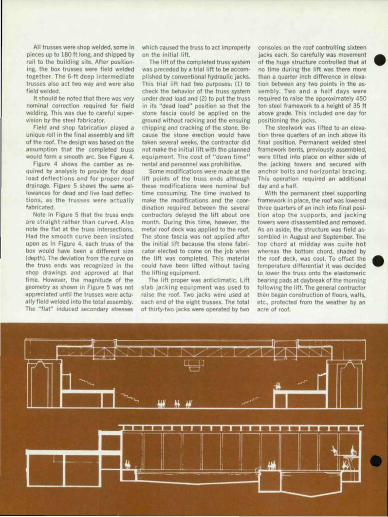
The Gymnasium, as the name implies, was designed for athletic events. The building is also intended for civic and theatrical events. Therefore, it was a design criteria that there be a minimum clear height over the playing floor of 35 ft. Because of this height requirement and the clear spans of over 200 ft, it was decided as basic to the design to field assemble the roof truss system on the ground and to lift the structure into place. It is this feature of the Coliseum that is presented here for consideration.
As the preliminary drawings developed it became apparent that the roof system could be field assembled on the ground and subsequently lifted into place. This would eliminate the building of more than an acre of falsework. More important, the mechanical, plumbing and electrical contractors were advised that they would be able to work on the ground rather than 35 ft above grade. It
•
c:

•
OTMNA"UM
' I
j
l
Architect: F. Carter Williams Raleigh, N. C.
Structural Enllinoor, Kahn & Furbush Raleigh, N. C.
General Contractor: Dickerson, Inc. Monroe, N. C.
Fabricat." Peden Steel Company Raleigh, N. C .
DIVINO
' .. ... CIHO

should be pointed out that the contract drawings proposed a lifting format The details of the format are not as important as the fact that this format made it common knowledge to all contracting parties that the field assembly and lift were basic. The validity of the lilt idea was proved by the fact that the competitive bids indicated a savings of approximately $70,000 in a total construction cost that amounted to a little over $2-million.
To fully appreciate the "lift" it is necessary to describe the design development of the roof structure in some detail. First of all, the site consists of a sandy silt that extends uniformly to a marl approximately 45 It below. The
water table in general is about 20 It below the existing grade. The site, therefore, dictated a pile foundation. Because of the long spans and concentration of heavy loads, the foundations dictated a roof structure that could tolerate some anticipated differential settlement
The truss supports evolved into cast in place concrete towers. It was logical to develop the eight towers into stairs for vertical movement of students and spectators. It was then logical to establish the previously shown "tic-tac-toe" framing geometry (Figure 1).
In general the "tic-tac-toe" trusses are double trusses forming a box. These box trusses form a "two-way" system. The box is 13 It high by 13'-6" wide.
Fig. 1. uric-rae-Toe" Double Trust Arrangement
• l
. ,... -,
i
•
•
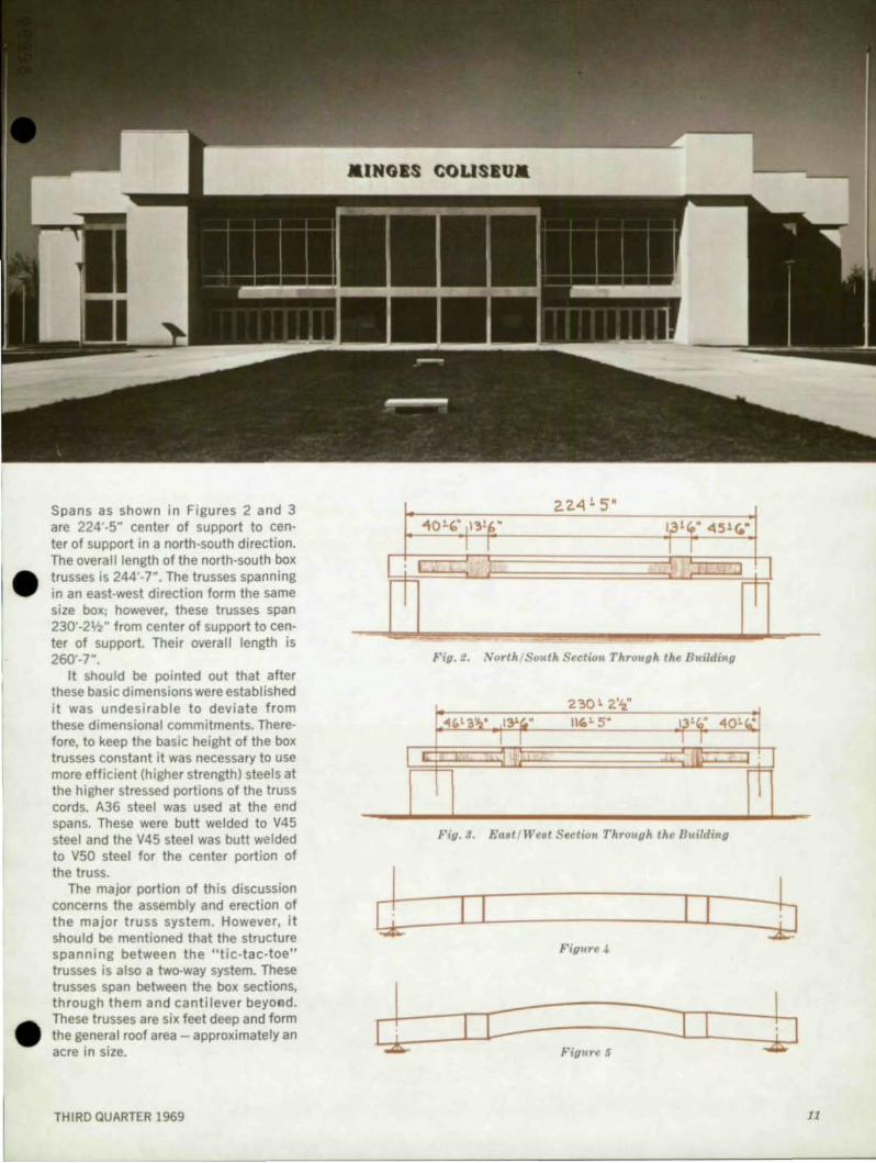
Spans as shown in Figures 2 and 3 are 224'-S" center of support to center of support in a north-south direction. The overall length of the north-south box trusses is 244'-r. The trusses spanning in an east-west direction form the same size box; however, these trusses span 230'-2'h" from center of support to center of support. Their overall length is 260'-r.
It should be pointed out that after these basic dimensions were established it was undesirable to deviate from these dimensional commitments. There· fore, to keep the basic height of the box trusses constant it was necessary to use more efficient (higher strength) steels at the higher stressed portions of the truss cords. A36 steel was used at the end spans. These were butt welded to V4S steel and the V4S steel was butt welded to VSO steel for the center portion of the truss.
The major portion of this discussion concerns the assembly and erection of the major truss system. However, it should be mentioned that the structure spanning between the "tic-tac-toe" trusses is also a two-way system. These trusses span between the box sections, through them and cantilever beyo~d. These trusses are six feet deep and form the general roof area - approximately an acre in size.
THIRD QUARTER 1969
T
2.2,4" 5' 40'" Ill!(,' 1,3',,' 45 1 (.'
I I I I ~ : ,
T ;
Fig. l . North. . Solttk Sectio~1. Through the Buildinf}
230' 2'"" .", 3 .... • 131'" IIIG'S' 13 !~' 10' "'.
I I I II
T Fig. 3. Ea8t / We8t Sectio,t Through the Building
II I I
I L------J.-L_±U· I Fi{/UTf' 5
11
All trusses were shop welded, some in pieces up to 180 ft long, and shipped by rail to the building site. After positioning, the box trusses were field welded together. The 6-ft deep intermediate trusses also act two way and were also field welded.
It should be noted that there was very nominal correction required for field welding. This was due to careful supervision by the steel fabricator.
Field and shop fabrication played a unique roll in the final assembly and lift of the roof. The design was based on the assumption that the completed truss would form a smooth arc. See Figure 4.
Figure 4 shows the camber as required by analysis to provide for dead load deflections and for proper roof drainage. Figure 5 shows the same allowances for dead and live load deflections, as the trusses were actually fabricated.
Note in Figure 5 that the truss ends are straight rather than curved. Also note the flat at the truss intersections. Had the smooth curve been insisted upon as in Figure 4, each truss of the box would have been a different size (depth). The deviation from the curve on the truss ends was recognized in the shop drawings and approved at that time. However, the magnitude of the geometry as shown in Figure 5 was not appreciated until the trusses were actually field welded into the total assembly. The Uflat" induced secondary stresses
which caused the truss to act improperly on the initial lift.
The lift of the completed truss system was preceded by a trial lift to be accomplished by conventional hydraulic jacks. This trial lift had two purposes: (1) to check the behavior of the truss system under dead load and (2) to put the truss in its "dead load" position so that the stone fascia could be applied on the ground without racking and the ensuing chipping and cracking of the stone. Secause the stone erection would have taken several weeks, the contractor did not make the initial lift with the planned equipment. The cost of "down time" rental and personnel was prohibitive.
Some modifications were made at the lift points of the truss ends although these modifications were nominal but time consuming. The time involved to make the modifications and the coordination required between the several contractors delayed the lift about one month. During this time, however, the metal roof deck was applied to the roof. The stone fascia was not applied after the initial lift because the stone fabricator elected to come on the job when the lift was completed. This material could have been lifted without taxing the lifting equipment.
The lift proper was anticlimatic. Lift slab jacking equipment was used to raise the roof. Two jacks were used at each end of the eight trusses. The total of th irty-two jacks were operated by two
consoles on the roof controlling sixteen jacks each. So carefully was movement • of the huge structure controlled that at no time during the lift was there more than a quarter inch difference in eleva-tion between any two points in the assembly. Two and a half days were required to raise the approximately 450 ton steel framework to a height of 35 ft above grade. This included one day for positioning the jacks.
The steelwork was lifted to an elevation three quarters of an inch above its final position. Permanent welded steel framework bents, previously assembled, were tilted into place on either side of the jacking towers and secured with anchor bolts and horizontal bracing. This operation required an additional day and a half.
With the permanent steel supporting framework in place, the roof was lowered three quarters of an inch into final position atop the supports, and jacking towers were disassembled and removed. As an aside, the structure was field assembled in August and September. The top chord at midday was quite hot whereas the bottom chord, shaded by the roof deck, was cool. To offset the • temperature differential it was decided to lower the truss onto the elastomeric bearing pads at daybreak of the morning following the lift. The general contractor then began construction of floors, walls, etc., protected from the weather by an acre of roof.

. ,J
' D
•
•
•
Elliot L. Whitaker, FAIA, comments on the 1969 AISC Prize Bridge Awards:
THE BRIDGE DESIGNER AND
In all recorded history, the bridge is perhaps one of man's greatest can· structed achievements, involving all of his daring, ingenuity and creativity. In primitive times his chief concern was to "bridge," or "get across," or IIlink," or "span" the obstruction, be it a small stream or a raging river, a simple ditch or a deep canyon. In fact, many early bridges were constructed in obscure, isolated places for few except the occa· sional user to see, and the aesthetic value of the completed bridge was really of little concern to either builder or user.
Today, refinements in engineering and technology, together with new mao terials of construction, including the new weathering and higher strength steels are available to challenge the bridge designer's technical imagination. The projected interstate highway system already completed in several areas of the country offers the designer almost limitless opportunities for new and dar· ing bridge ideas. Moreover, as America continues towards increased urbaniza· tion, fewer bridges are built in isolation, and each new bridge must be consid· ered as a necessary and important segment of the total society it serves.
The designer is now asked to demonstrate that he does consider his bridge in the context of social consciousness. His responsibilities to society include more than just providing for the safe and easy movement of people and traffic; his completed bridge, like a work of architecture, is judged and evaluated on how well it is constructed. how well it serves the purposes for which it was planned, how well it looks, and how well it fits into the total environment it serves. The designer must pay attention to the "total" aesthetics of his bridge-
THIRD QUARTER 1969
SOCIETY
Mr. Whitaker, Director of the School of Architecture, Ohio State UlliveraitJl. H'a' chairman of the Jury 01 Au'm'd, for the 1969 AlSC Prize Bridge Competition.
the proportion and shape of each structural member in relation to the entire bridge. the transition from one material to another. including the relationship of the steel to the supporting members and abutments, the bridge color in relation to its surroundings, and the bridge setting in terms of safe, easy, well landscaped approaches and clearances. Aesthetically, a bridge in its environment or setting is a "total" design, and in the best sense must be accepted as one of the great art forms of the 20th century.
The Jury for the 1969 Prize Bridge Competition was encouraged with the large number of beautiful structu res submitted. and to note the bridge designer's increasing focus on the aesthetics, safety, and sensitive concern for the environment.
In proving the point that the design of a small bridge, no less than the design of a large bridge, must concern human satisfaction, aesthetic needs, social progress, and must show a sensitive concern for its environment, the Jury broke precedent to commend two bridges in the category of Special Type Bridges, and selected them as co-winners, one is the Dodge Street Overpass, a pedestrian bridge in Omaha, Nebraska. The Jurors' comments were:
"This 'people' bridge is a beautiful and logical solution for a pedestrian crossing of a highway. It is handsome from many viewpoints; for the motorist who goes beneath it and for the pedestrian who passes over it. It adds a note of interest and gaiety to the crossing of a busy highway. The designer should be complimented for his attractive treatment of the slender piers and his careful attention to thegeometrywhich resulted in smooth uninterrupted curves."
The other co-winner is the Queens Zoo-Aviary Pedestrian Bridge in the Flushing Meadows-Corona Park, New York. The Jurors' comments were:
"This graceful pedestrian bridge inside a domed aviary makes its own artistic statement. It is an enjoyable design, light and airy. Constructed of colorful, weathering steel it achieves a 'playful' effect and is completely compatible with the dome around it. Its slender effect would be difficult in any material other than steeL"
In conclusion, the Jury commends the American Institute of Steel Construction for its four decades of continuing concern for the appearance and aesthetics of America's bridges. Indeed, the results of its efforts are clearly demonstrated in all sections of the country.
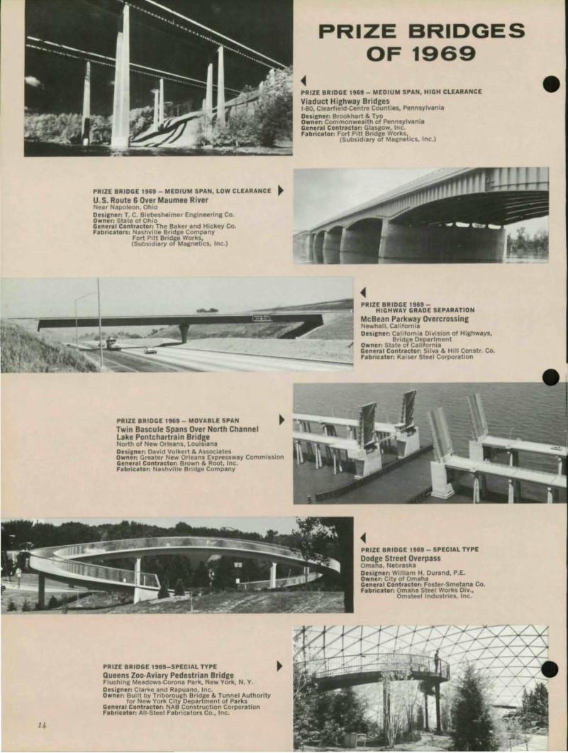
PRIZE BRIDGE 1969 _ MEDIUM SPAN, LOW CLEARANCE ~ U.S. Route 6 Over Maumee River Near Napoleon, Ohio Dtsilnar: T. C. Biebesheimer Engineering Co. Owner: Stale of Ohio General Contractor: The Baker and Hickey Co. Fabric.tors: Nashville Bridge Company
Fort Pitt Bridge Works, (Subsidiary of Magnetics, Inc.)
--
PRIZE BRIDGES OF 19a9
PRIZE BRIDGE 1969 - MEDIUM SPAN, HIGH CLEARANCE
Viaduct H,ighway Bridges 1-80, Clearileld-Centre Counties, Pennsylvania Desi,n.,: Brookhart & T)'o Owner: Commonwealth of Pennsylyani. Gener.' Contractor: Glasgow, Inc. Fabricator: Fort Pitt Bridge Works,
(Subsidiary of Magnetics. Inc.'
PRllE BRIDGE 1969 -HIGHWAY GRADE SEPARAT ION
McBean Parkway Qvercrossing Newhal" California Desilner: California Division of Highways,
Bridge Department
~~§~~;::~':~ _____ -' _________ "':.:.. __ <': Owner: State 01 California General Contr.ctor: Silva & Hill Constr. Co. Fabricator: Kaiser Steel Corporation
PRIZE BRIDGE 1969 - MOVABLE SPAN •
Twin 8ascule Spans Over North Channel lake Pontchartrain Bridge North of New Orleans, louisiana Desilner: David Volkert & Associates Owner: Greater New Orleans Expressway Commission General Contractor: Brown & Root, Inc. Fabricator: Nashville Bridae Company
PRIZE BRIDGE 1969-SPECIAL TYPE
Queens Zoo-Aviary Pedestrian Bridge Flushing Meadows-Corona Park, New York, N. Y Desilner: Clarke and Rapuano, Inc. Owner: Built by Triborough Bridge & Tunnel Authority
for New York City Department of Parks General Contractor: NAB Construction Corporation Fabriutor: All-Steel Fabricators Co., Inc.
PRIZE BRIDGE 1969 - SPECIAL TYPE
Dodge Street Overpass amalia, Nebraska Desirner: William H. Durand. P.E. Owner: City of Omaha General Conlr.clor: Foster·Smetana Co. Fabricator: Omaha Steel Works Oiv.,
Omsteel Industries, Inc.
•

•• . ,
•
•
AWARD Of MERIT 1969 - LONG SPAN
Delaware Memorial Bridge (Second Structure) New Castle, Del. to Pennsvifle. N. J.
DUi&ner: Howard, Needles, Tammen & Bergendoff E. Lionel Pavia, DScCE, ConsultinK Engineer
Owner: Delaware River and Bay Authority Ge neral Co ntractors:
Superstructure: Schiavone Construction Co., Inc. Buckley & Co., Inc.
Substructure: Steers-Perini-Pomeroy Franklin Contracting Co. Ruckman and Hansen, Inc.
FabricatOrl: Bethlehem Steel Corporation, Harris Structural Steel Co.
AWARD OF MERIT 1969 - Irrrrrrr..
MEDIUM SPAN, HIGH CLEARANCE ,.
Kern River Br idJe Near Isabella, Cal.fornia Desianer: California Division of Highways,
Bridge Department Own er: State of California Genera l Co ntractor: Obera Construction Corp. Fabricator: Pittsburgh-Des Moines Steel Co,
AWARD OF MERIT 1969 - SHORT SPAN ~
Keystone Shortway Bridge Over Beaver Creek
Near Knolt, Pennsylvania Desilne,: Rummel, Klepper & Kahl Owner: Commonwealth of Pennsy lvania General Contractor: Frank Mashuda Co., Inc. Fabricator: American Bridge Oivision,
United States Steel Corp.
AWARD OF MERIT 1961-MEDIUM SPAN, HIGH CLEARANC E
Brandywine Creek Br idge Wilmington, Delaware Desilner: Howard, Needles, Tammen & Bersendoff Owner: State of Delaware General Contract or:
Superstructure: BUraer Construction Corporation Substructure: Kaufman Construction Company, Inc.
Fabrica to r: American Bridge Division, United States Steel Corporation
AWARD OF MEAIT 1969 - SHOAT SPAN
Scott River Bridge Siskiyou County, California Desilner: Clair A. Hill & Associates Own er: Coun ty of Siskiyou Genera l Contractor: Continental Construction Co .• Inc. Fabricator: San Jose Steel Company. Inc.
15

PRIZE BRIDGES 1969 (conl'd)
AWARD OF MERIT 1969 - .... HIGHWAY GRADE SEPARATION ,..
Rew Interchange West of Pendleton, Oregon Designer: Bridge Division
r Oregon State H ghway Dept. Owner: State of Oregon General Contractor: Rogers Construction, Inc. Fabricator: Northwest Steel Fabricators, Inc.
AWARD OF MERIT 1969 - SPECIAL TYPE
Milwaukee Country Club River Bridge River Hills, Wisconsin Designer: Howard, Needles, Tammen & BergendoH Owner: Milwaukee Country Club General Contractor: Joseph D. Bonness,J. Inc. Fabric.tor: lakeside Bridge and Steel 1,;0.
AMERICAN INSTITUTE OF STEEL CONSTRUCTION 101 Park Avenue New York, New York 10017
Address Correction Requested
AWARD OF MERIT 1969 - SHORT SPAN
Sandisfield BridRe No. 5·3-33 • u . S. Route 8 over f!armington River, Mass. Designer: Massachusetts Dept. of Public Works,
Bridge Section Owner: Commonwealth of Massachusetts General Contractor: Petricca Constr. Co. Fabricator: Tower Iron Works
AWARD OF MERIT 1969-HIGHWAY GRADE SEPARATION
Riverside Drive Over the Dalles-California Highway
Near Klamath Falls , Oregon Designer: Bridge Division,
Oregon State HIghway Dept. Owner: State of Oregon General Contractor:
Slate·Hall and Hamilton Constr. Co. Fabricator: San Jose Steel Company, Inc.
BULK RATE U.S. POSTAGE
PAID DANBURY, CONN. PERMIT NO. 97
•