1. abstract · the literature in this developing sector of laser communication methodology. 3....
TRANSCRIPT

Enclosure (3) 1
Experimental Analysis of Laser Light Propagation and Scattering of Beams with Varying Degrees of Spatial Coherence for Application in an Underwater Environment
Experimental Performance Analysis of Laser Beams with Varying Degrees of Spatial Coherence Underwater
DESCRIPTION OF PROPOSED METHOD OF INVESTIGATION
1. Abstract The US Navy has investigated underwater laser link communications due to the potential
benefits of increased data transmission speed and security. Submarines, Unmanned Underwater Vehicles, divers, and underwater sensor arrays would all reap these benefits. The US Navy is pursuing both experimental and theoretical solutions to the challenges of propagating lasers underwater. Laser beams propagating through complex medium experience distortion. Predicting and overcoming this phenomenon in random media has become the key to advancing the feasibility and reliability of underwater optical communications. In the underwater environment, laser light experiences fluctuations in the index of refraction due temperature and salinity variations, and also experiences attenuation due to particulate matter suspended in the medium. These factors combine to create systems that are difficult to model and predict, and provide an interesting opportunity to determine which specific type of laser beams propagate best in these environments.
The proposal involves the design, construction, instrumentation, and commissioning of an emulator chamber which will provide a reliable and scalable test bed in which the turbidity, water flow, salinity, and temperature gradients will be controlled. The design and the construction of the emulator will begin this spring and its evaluation will be the primary task in the fall. Development and characterization of the emulator will provide an invaluable resource to the long-term exploration of laser propagation and scattering underwater. Experimental and theoretical sources provide extensive literature, detailing the methodology for the generation of spatially partially coherent laser beams, generated from a stabilized HeNe laser and modulated via a spatial light modulator. The novelty of the proposed project is the propagation of the spatially partially coherent beams in the underwater environment. This project will measure the effects experienced by the beams for both off- and on-axial directions. Cameras will be used to record laser light intensity fluctuations due to scattering and propagation. Data processing will focus on determining the performance parameters for various underwater conditions and different types of the beams. The goal of this project is to experiment using laser beams with variable levels of spatial coherence and analyze them for both propagation and scattering effects experienced in controlled underwater conditions and determine the advantages and disadvantages for their use in laser communications.

Enclosure (3) 2
2. Objectives This project will result in the design, construction, instrumentation, and commissioning
of an emulator chamber for use in simulating scalable underwater environments. This emulator will allow for control over the temperature, salinity, and turbidity of the water within predetermined limits, and will provide the means to measure these environmental parameters during experimentation.
The emulator will be characterized in such a way that it could be used in mathematical modeling process regarding propagation of beams with varying degrees of spatial coherence. This process will be taken from published experimental and theoretical sources regarding the creation and propagation of these beams, particularly through turbulent media.
Beams of varying degrees of spatial coherence will be propagated using previously established methods for the propagation of these beams within an experimental setting, utilizing a stabilized HeNe laser and a spatial light modulator. The creation of these beams will be verified using the lab equipment before any propagation in the test bed is done.
Using on- and off-axial cameras, data on the intensity and intensity fluctuation of the beams will be collected. On-axial data will determine the performance of the beams regarding propagation, and the off-axial data will determine the scattering effects the beam experiences as it propagates. This data will be analyzed using statistical methods and compared against the performance of a standard Gaussian beam, which will be identified as the control beam. This performance analysis will lead to a determination of which beams are better suited for communication purposes in the underwater domain.
While the test scenario in the larger scale involves two Navy Divers attempting to communicate using laser link communications at varying depths, distances, and in various environments, this project examines only a small portion of the myriad of problems associated with making that scenario a reality. The scattering and propagation analysis of the beam types in different environments will be the only definite deliverables from this project, however, the unique and powerful nature of this contribution to the field of laser propagation and communication must not be understated.
Time permitting, an additional possible outcome of this experiment relates to the previously established mathematical models for the propagation of beams of varying spatial coherence. These models will be analyzed using the experimental data collected from the generation and propagation of these beams. Validating or disproving these models will expand the literature in this developing sector of laser communication methodology.
3. Background Laser communication is on the cutting edge of the telecommunication sphere, as the
speed and accuracy of these communications has far exceeded the standards set by previous communication methods. Many significant strides have been taken in this field, particularly in the area of free-space optical communications, or communications through light propagating through free space. Outside of the massive increase in transmission accuracy, speed, and volume, directed optical communications such as laser communications are also significantly more secure

Enclosure (3) 3
than other means of communication, operating in a line-of-sight wave propagation, in contrast to an omnidirectional propagation path, as seen in most Radio and Acoustic Transmission systems [1-3].
NASA in particular has invested time and money into researching laser link communications due to the perceived advantages. In a number of successful trials, NASA determined that laser link communications are able to transmit well within the same operational parameters as the best Radio Frequency communication systems with a significantly reduced tax on the power systems and a much smaller interface.
Within the Navy specifically, the capabilities provided by laser communication systems are being looked at as the next step in rapid and secure tactical and strategic communication. While laser communication technology does rely on a “line of sight” for the laser to travel from terminal to terminal, it offers a significantly higher resolution, transmitting much more data accurately, as well as greatly reducing the latency effect experienced by radio frequency communications at longer distances. This technology is being examined specifically for implementation on ships and aircraft, as well as at airfields and on other tactical platforms. It can also be used for specific person-to-person communications amongst units in any type of environment [1].
Within the Navy’s operational environment, undersea laser communications has drawn particular attention in recent years, focusing on the feasibility of laser link communications between submersible vehicles, sensor arrays, or divers. More so than terrestrial environments, the undersea environment offers unique challenges in both beam propagation and attenuation. The undersea environment has been a communication’s challenge for decades, as RF communications are significantly less effective underwater, facing major propagation issues well before reaching the common operational depths at which submarines function. Large power stations are required to create the low frequency waves which can penetrate to any useful depths, often meaning that the transmissions are limited by the power available to both the sender and the receiver to generate a two-way communication system. Additionally, the bandwidth is so low that these low frequency (LF) waves fail to transmit the massive amounts of data required in tactical combat scenarios, or for operating Unmanned Underwater Vehicles (UUVs) or other similar robotic systems [2].
The major challenges facing laser communications center on loss of beam intensity and intensity fluctuations over long distances and through different mediums. In a vacuum, laser communication is ideal because it travels through only one medium, and has a much lower chance of being obstructed or interrupted once the data has been sent. In terrestrial environments however, there are considerable challenges presented by not only the obscuring effect from fog, rain and other airborne particulates, but also the varying of the index of refraction due to temperature gradient changes, which affect the beam path and results in constructive and destructive interference upon reception. Bit-error rate, or the rate at which transmission errors occur, is a huge focus for the study of laser link communications, since the small attenuation factors may have significant effects if hundreds or thousands of bits per microsecond are being lost. When the intensity level of the incoming irradiance decreases below the detection threshold of the detector, no data is absorbed or processed from that particular instance of transmission until the intensity subsequently increases again. Minimizing the possibility of a high bit-rate error is paramount in the development of feasible and dynamic

Enclosure (3) 4
optical communications [3]. Despite the importance of this aspect of laser communication, the investigation proposed will not deal directly with this phenomenon, but will instead work to extend the current literature on underwater propagation so that the technical aspects of the communications systems, such as bit-error rate, can be addressed when the actual creation of these systems is undertaken.
In contrast, lasers can provide solutions to the power and propagation issues commonly seen in RF communication, while operating at significantly higher bandwidth underwater as well. The major issues facing laser communication in the atmosphere, namely from light waves scattering via particles in the medium, and optical turbulence are magnified in the highly variable underwater environment due to additional effects from salinity and turbidity [3].
Specifically for the Navy, major scenarios in which laser communications would be useful are submarine-to-submarine, submarine-to-UUV, and diver-to-diver communications. For these scenarios in which it is of critical importance that messages between parties not only contain the data message in its entirety, but also provide a secure and effective means of delivering this message, the increased transmission speed and security of laser communications would be an invaluable asset.
4. Lasers and Laser Characteristics To introduce the concepts behind the propagation of laser light in an underwater
environment, let us present what lasers are and how they actually work. The term “laser” actually originated as an acronym, created by the phrase “light amplification by stimulated emission of radiation.” It is a term used to describe a device which emits optically amplified light, either in short pulses or continuous beams. Laser light and light from a light bulb are different in the characteristics of the radiation produced by the light source and how it spreads. Conventional light sources emit photons in random directions, each with differing wavelengths and phases. In contrast, lasers convert energy into light through the use of what is called stimulated emission, which is basically a chain reaction of photons creating more photons through interactions with atoms in the given direction of travel. These photons all have the same wavelength, direction, phase, and polarization. These photons travel as electromagnetic waves, oscillating orthogonally down the direction of propagation as seen in Figure 2 [6].
Figure 2. Schematic representation of Electromagnetic waves [7].
5.1 Monochromaticity
When the photons pass by atoms in the stimulated emission, they theoretically all have the same energy level, which also dictates their wavelength. Ideal lasers emit all photons at the

Enclosure (3) 5
same wavelength, though practically lasers do not experience perfect monochromaticity. For lasers that emit visible light, this means that they all emit the same visible color, though that is not a requirement for lasers, since they can also emit at higher or lower wavelengths which could move them out of the visible spectrum and into other regions of the electromagnetic radiation spectrum. Emitting light of the same wavelength can allow certain lasers to perform better or worse in certain environments, like the ocean, depending on which wavelengths are more prone to attenuation in comparison to others [6].
5.2 Coherence Laser light is, by nature, coherent. Light can be both temporally coherent and spatially
coherent. Figure 3 describes spatial coherence.
Figure 3. Diagram displaying the creation of spatially coherent light from an incoherent light
source using a pinhole aperture, and the separation of a single wavelength via filter to create
temporal coherence. Lasers exhibit this high degree of coherence by nature [8].
5.2.1 Temporal Coherence
Temporal coherence deals with the phase correlation of waves at a given point in space
at different instances of time, and has to do more with how a wave can create interference with
itself, as with a Michelson Interferometer. Light that is perfectly monochromatic, containing only
one frequency, correlates perfectly with itself at all time delays by definition [6].
5.2.2 Spatial Coherence
Spatial coherence has to do with the coherence between two different spatial locations on a laser at one single point in time. Ideal lasers emit photons which are all perfectly in sync in phase, resulting in a single uniform wave front. This is unique to lasers, or light created from a single point source, and has a particular effect in creating interference patterns, demonstrated in Young’s famous Double Slit experiment, which can be used for any number of laser light practical applications. Light created by conventional means not only emits light as radiated energy from a source, but also emits incoherent light, meaning that the individual electromagnetic waves are not in phase, or ever in the same wavelength. Through the use of a pinhole filter as well as a wavelength filter, light from a conventional source can be selectively isolated to display coherence similar to laser light [6]. Through the use of a laboratory tool called a “Spatial Light Modulator”, the spatial coherence of beams can be controlled using statistical methods discussed at length in previously conducted experiments examining the properties of these unique beams [SAZ Submission].
Temporally

Enclosure (3) 6
5.3 Collimation Collimated light is the term used to describe light which has completely parallel rays,
meaning that it will spread minimally throughout propagation. Perfectly collimated lasers do not exist due to diffraction, though laser light is referred to as “highly collimated” due to its tendency to remain converged over large distance in comparison to normal light. Despite this, all lasers do experience dispersal over distance due to not being perfectly collimated [6].
6. Propagation Now that we understand the basics of how laser light propagates, and why it is unique, it
is important to also understand what happens between the laser emission and the end target whatever it might be. In an ideal situation, the laser would not lose any intensity as it traveled to its target, but that is not the case. Depending on whatever the given medium of propagation is, the wave flux will gradually lose intensity as the distance increases, as the energy is both absorbed and scattered by whatever is in the medium.
6.1 Divergence
Laser light is also subject to a certain degree of divergence as distance increases as well. Divergence is the increased diameter of the beam as distance from the aperture of propagation increases. Though not the same as attenuation, divergence is also a very important factor to consider when discussing the merits of communication using laser light, particularly at long ranges when the divergence of the beam could be a limiting factor to the effectiveness of the transmission. Beams that have spread, such as communications at a great distance place a higher stress on the receiver module, not only in the size of the receiver which needs to be increased due to the outward spreading of the beam, but also in computational power since beams attenuate more and in different ways as they spread, due to the environment changes along the beam path. [9, 10].
6.2 Refraction In addition to divergence, refraction is the phenomenon which causes light to bend as it
passes through a medium. This is quantified in the angle the particular light wave makes with the

Enclosure (3) 7
normal of the surface. These angles are related by Snell’s Law (below), which led to the creation of the refractive index coefficient for different mediums, which is the ratio of the sine of the angles in reference to how light behaves in a vacuum. Figure # shows a ray path and the incidence angle change with the change in refractive index.
n1 ∗ sin (ϴ1) = n2 ∗ sin (ϴ2) Figure 6. Refraction via Snell’s Law, where ϴ1/ϴ2 are incident and refracted angles
(respectively), and n1/n2 are the indices of refraction for each medium [16]. Understanding refraction is important because refraction ultimately dictates the
directional path that the laser light will take in passing through a medium, and particularly a number of non-uniform mediums, such as the atmosphere or sea water. If the end goal is to impart some radiation on a target, whether it be for communications using optical systems or for damage via a directed energy weapon, understanding the way that light refracts through different mediums is incredibly important if the target is ever to be reached [6, 11, 12].
Beam wander is an effect in which the beam’s path is altered by the medium due to the varying speeds at which the beam travels. This can result in the beam reaching a different destination than originally desired, potentially off of the receiver which could cripple the message. The figure below demonstrates beam wander and the effects it has on the received power.
6.3 Absorption
Depending on the medium of propagation, photons will have interactions with the atoms within this medium. These interactions differ greatly depending on the atoms in question and their energy levels, but serve as a piece of the total attenuation for laser light, meaning that it contributes to the gradual extinction of laser light intensity. Each particular type of atom has a different absorption coefficient assigned to it, meaning that propagation of the same wave through different mediums will result in variable levels of absorption. The amount of energy that can be absorbed by a medium, different gases for example, depends on the complexity of the atoms or molecules that the photons are interacting with, as there has to be some way for the atom or molecule to store the energy being imparted by the photons. This is usually done by advancing an electron to a higher energy state, thereby exciting the atom or molecule. The absorption interaction also depends on the wavelength of the incident photons. Some gases will only absorb light in a range of wavelengths, while others may only absorb light at one very specific wavelength [13, 14].

Enclosure (3) 8
6.4 Scattering Just as light can be absorbed in its interactions with particles, scattering also adds to
attenuation by changing the physical direction of propagation of the electromagnetic waves, as opposed to absorbing their energy outright. Scattering occurs when the photons passing through the medium have actual physical interaction with particles within, and as a result of these collisions, change direction. Scattering is a function of a number of elements related to the propagation medium, namely size and shape of the particle, index of refraction, wavelength, and geometry. This is problematic for laser light because the light is no longer propagating in the intended direction, meaning that the scattering effect contributes to the overall amount the beam intensity is decreased over a certain distance. Despite a medium having a low absorption coefficient, that medium can still maintain a high attenuation coefficient depending on how much of the incident radiation is scattered by those molecules inside. A perfect example of this is the attenuation challenges presented by clouds. Clouds present very low absorption losses, yet very high scattering losses, as indicated by their white color, which means the particles within the clouds scatter light of all wavelengths, which is what is received by our eyes [14].
There are three major types of scattering, determined ultimately by the size of the particle interacting with the beam.
Figure 7. Diagram of Mie and Rayleigh Scattering and scattering patterns observed for each
type [22]. For molecules and particles that are larger than the wavelengths of the light interacting
with them (within the visible spectrum for this discussion), the radiation experiences Mie Scattering. Mie scattering is commonly caused by pollen, dust, smoke, water particles, and other objects of a similar size. Mie scattering is what causes clouds to appear white, as the water particles scatter visible light of all wavelengths, making them appear white [16].
The second major type of scattering is Rayleigh scattering. Rayleigh scattering is wavelength dependent, and is ultimately what causes the sky to appear blue. It is caused by particles smaller than the wavelength of the incident light, such as atmospheric gas particles. In our atmosphere, the white light from the sun is scattered by the gas particles, with the blue wavelength scattering the most. This is why the sky has a blue color, since the visible blue wavelengths are making it to the surface in greater density than any other visible wavelength. Figure 8 is a diagram of this phenomenon in the atmosphere, displaying how the scattered light of a blue visual wavelength is scattered down to the surface [7].

Enclosure (3) 9
Figure 8. Diagram of Rayleigh Scattering and how it occurs in the atmosphere to produce the appearance of a blue sky [22].
The last type of scattering is called non-selective scattering, and it occurs when the
particles are significantly greater than the wavelength of the incident light. This type of scattering affects all wavelengths, hence the “nonselective” moniker. This type of scattering contributes to the effects that haze, fog, and dust have in the atmosphere.
Figure 9. Scattering regimes with respect to wavelength (λ), particle cross-sectional size r, and
size parameter (χ) [7].
6.5 Reflection Reflection is what drives the primitive understanding of scattering as a source of
attenuation. It is important to make the distinction between reflection and refraction, as each has its own particular effects on the propagation of waves. Reflection involves changing the direction of the electromagnetic waves without allowing propagation through whatever object or medium the light is interacting with. This contrasts with refraction, which involves the changing direction while still allowing propagation. For most mediums, both reflection and refraction occur in varying degrees, ultimately determining the feasibility of the medium as a propagation medium for whatever electromagnetic radiation is in question [6].

Enclosure (3) 10
6.6 Optical Turbulence Optical turbulence is a type of turbulence which also has an effect on the propagation of
waves. Optical turbulence occurs when the index of refraction of the medium changes, usually because of thermal stratification throughout the medium. This effect has seen particular attention because of the ramifications it has on optical communications throughout the atmosphere. While a small difference in atmospheric density may only yield a change in angle incidence of far less than 1%, this value compounds with distance, and can change the end position of a laser light spot by as much as a number of meters. Figure # below is a simple demonstration of the effects small eddy currents in the propagation medium result in optical turbulence.
Though optical turbulence has a considerable effect on waves propagating through the atmosphere, it has an arguably stronger effect on the propagation of waves through water, such as the ocean. This is because the underwater domain can possess highly stratified characteristics for both temperature (thermocline) and salinity (halocline), making light propagation even more difficult [11]. Optical Turbulence is quantified by the refractive index structure parameter, Cn
2, and is a function of the local environmental parameters affecting the index of refraction at any given discrete location. Cn
2 value for the atmosphere has been examined at great length, but has been investigated less in the underwater environment. Cn
2 is related to the refractive index variance over very small distance increments [17].
Figure 4. demonstrates the varying levels of intensity for beams passing through two mediums of differing Cn
2 value [18]
Figure 4. Display of beam intensity difference for identical beams passing through mediums of different Cn
2 value. Higher intensity indicates greater intensity fluctuation [18].
Scintillation is another effect that propagating beams can experience. Scintillation is the fluctuation of light intensity, manifested in the appearance of twinkling light. This effect is also caused by disturbances in the propagation medium, namely optical turbulence [6]. This effect can cause a variable detected intensity which can drop below the detection threshold for the receiver, resulting in data losses and errors. Figure 5. demonstrates this effect.

Enclosure (3) 11
Figure 5. Scintillation attributed to turbulence [20]
6.7 Turbidity Turbidity is the measure of the degree to which the medium of propagation loses
transparency due to suspended particulates, which ultimately contributes to scattering and absorption. This particulate matter can range from very small microscopic particles to larger macroscopic particles. Turbidity is frequently used to describe the transparency of water, however it can also be used to describe the atmosphere. For atmospheric turbidity, there is a turbidity factor which can be measured experimentally, or loosely approximated mathematically. In water, the unit to measure turbidity, called the nephelometric turbidity unit, or NTU. Understanding the characteristics of the environment regarding turbidity would help determine the amount of power a laser would need to travel a certain distance as it plays a large role in the determination of attenuation, particularly scattering [15].
7. Propagation Through Water Laser propagation through differing mediums has become an area of acute focus by
researchers working on increasing the feasibility and utility of free space optical communications. Much of the research that has been done on the subject involves analysis of laser beams through air, specifically through the atmosphere. Attenuation in a complex medium such as the atmosphere or underwater presents significant challenges not apparent in laser propagation through a vacuum. This is due to the impact that environmental factors have on all of propagation effects listed above [16].
To accurately predict the path and power of laser light as it propagates under water, a number of variable quantities, each with the ability to affect the path and power of the beam, must be examined. The temperature, turbulence, turbidity, and salinity of the water all have significant effects on the wave power and path, as they can each influence the refractive index of the medium through which the light travels [16]. These environmental parameters are highly variable for differing sea states, geographic locations, and depths, all of which need to be considered in the emulation of the real world environment.
Laser light attenuates due to the presence of molecules in the medium as the energy passes through it. In the atmosphere, these particles are called aerosols. This same effect can be seen with particulate matter suspended underwater as well. Unlike scattering, which redistributes the energy of the incident light, absorption converts the energy of the incident light to the molecules, which commonly manifests as heat energy [13]. At times, very high energy directed energy lasers can experience an effect known as thermal blooming, which is the result of rapid high energy transfers which manifest as extreme changes in the temperature of the medium, greatly affecting the refractive index [23]. This is part of why high energy lasers cannot

Enclosure (3) 12
be used in the underwater domain, as they experience thermal blooming, just as some types of high energy beams experience in the atmosphere. Absorption through seawater is generally quantified by its four component pieces, which are added together to result in one absorption coefficient for that type of seawater. These four components are pure seawater, phytoplankton, nonalgal particles, and colored dissolved organic matter. These elements are different in waters all around the world, and contribute to the turbidity of the water. Examining the unique quality of the water in question which is going to be modeled is imperative so as to closely match the absorption coefficient components as possible to create a similar absorption loss [24-26]. Attenuation underwater is dominated primarily by absorption in the clearer oceans, and sees varying fluctuations of composition of particular absorption components depending on depth and the turbidity of the water [14]. Figures 10 and 11 demonstrate visually why the ocean appears blue, as it experiences the least absorption out of the different colors in the visual spectrum.
Figure 10. Imaging of visual light absorbed at varying wavelengths and depths. Shallow depth
indicates high absorption [27].
Blue Light

Enclosure (3) 13
Figure 11. Absorption Coefficient aw as a function of incident light wavelength in pure water [14].
In coastal and lake waters, scattering by optical turbulence has a more pronounced effect on beam propagation than in many other mediums. Optical turbulence is the result of variations in the index of refraction for the given medium, which can lead to a changing of the direction of propagation and subsequently lead to scattering. Optical turbulence in water can result from anything as small as a minor temperature fluctuation along the path of beam propagation, or from a salinity change along that same path. The effects these changes would have on beam propagation would be more and more pronounced along a longer path of propagation, which increases the likelihood of major environmental changes being experienced along the path of propagation. In seawater, the effects of temperature and salinity fluctuations on the refractive index change with depth, as halocline and thermocline environments exist in the ocean. Experimentally, temperature has a more pronounced effect on the creation of optical turbulence in the ocean [26, 28]. Due to the nature and composition of seawater, the common type of scattering experienced would be Rayleigh scattering, due to the size of the scattering particles in relation to the wavelength of the incident light. Seawater includes the entrained salt particles which creates salinity, and salt particles are generally sized on the order of 0.2nm, compared to for example a 600nm laser beam [29].
8. Literature Review
8.1 Spatial and Temporal Dispersion in High Bandwidth Underwater Laser Communication Links [1]
Goal
Summarize experimental and modeling efforts currently ongoing at NAVAIR Pax River,
MD which attempt to gain insight into the effects, both spatial and temporal, of scattering in
underwater optical communications. Spatially, an experiment was derived to observe the effects
of scattering and overall attenuation, as well as a temporal experiment which determined the
modulation of the signal as it passes through the medium.
Results
The conclusion was reached that laser links would ultimately have strongest utility
underwater in shorter range scenarios, and that the spatial and temporal effects of scattering
must be considered when creating any sort of underwater laser link. In this particular paper, the
spatial effects of scattering were examined, followed by the temporal effects. Figure 16 is a
preliminary example of the findings regarding the applicability of laser links in terms of range
relative to off axial positioning of the receiver, defined by r. This experiment was performed by
propagating a laser through a water tank, and recording the resultant output from the receiver
on the other end for different positions. The diagram for this experiment is included below.

Enclosure (3) 14
Figure 15. Diagram of Beam Spread Function due to Scattering Experimental Set-up
This is a demonstration of the temporal effects scattering has on a propagating wave, as
it is evident that the power lessens significantly as the off-axial distance increases, though the
feasibility of a link at lower ranges is still valid due to the beam spreading from scattering.
Figure 16. Received Power vs Link Range in meters
Regarding temporal effects on laser waves, a similar experiment was performed, but the
intensity modulation was measured instead of the received power for the offset. Different water
turbidities were used to determine the modulation depth experienced by waves propagating
through the water. Figure 17 shows the experimental set up diagram for this section.

Enclosure (3) 15
Figure 17. Temporal modulation on waves experimental set-up
The findings from this section concluded that the signal-to-noise losses experienced by
waves propagating underwater is more likely the result of absorption and scattering, as opposed
to modulation losses, particularly at these short ranges. Figure 18 demonstrates this effect in the
very minimal differences observed for each of the different turbidities.
Figure 18. Modulation Depth vs position for varying water turbidities

Enclosure (3) 16
Ultimately, it was concluded that the tests needed to be done at longer ranges and
variable laser characteristics and scenarios if the investigation was to continue with more
valuable results.
Project Utility
This project was a look into the challenges provided by underwater parameters on laser
optical communication links. The spatial and temporal effects on the beams were observed and
quantified as ranges similar to what will be used in this project. The investigative process used in
setting up the experiments, and the measurement and mathematic processes behind the
determinations of the experiment will be of great use in this project, after the emulator has been
constructed. Understanding the specific components which contribute to attenuation in the
underwater environment and which are specifically relevant to both the motivation scenario for
this project and other scenarios which could be experienced in the real world is very important,
since this project suggests that the attenuation components may have different weights at
different ranges.
8.2 Underwater optical wireless communications: depth dependent variations in
attenuation [14]
Goal
The goal of this study was to investigate how the ocean composition affects attenuation
of communication links, specifically along the z axis of depth. This paper also looked at other
studies which investigated underwater communication links. Using characteristic variables
related to the depth of the water, such as temperature, salinity, and chlorophyll distribution,
calculations about the true attenuation coefficient were made along those same gradients in an
attempt to describe the relationship between varying depths, wavelengths, and attenuation. This
study focused specifically on chlorophyll and the relationship between depth and attenuation.
Enclosure (3) 17
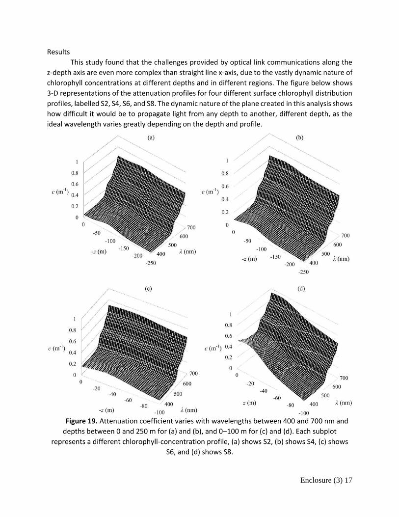
Results
This study found that the challenges provided by optical link communications along the
z-depth axis are even more complex than straight line x-axis, due to the vastly dynamic nature of
chlorophyll concentrations at different depths and in different regions. The figure below shows
3-D representations of the attenuation profiles for four different surface chlorophyll distribution
profiles, labelled S2, S4, S6, and S8. The dynamic nature of the plane created in this analysis shows
how difficult it would be to propagate light from any depth to another, different depth, as the
ideal wavelength varies greatly depending on the depth and profile.
Figure 19. Attenuation coefficient varies with wavelengths between 400 and 700 nm and
depths between 0 and 250 m for (a) and (b), and 0–100 m for (c) and (d). Each subplot
represents a different chlorophyll-concentration profile, (a) shows S2, (b) shows S4, (c) shows
S6, and (d) shows S8.
Enclosure (3) 18
The least attenuated light at a certain depth could be as far as 100nm away from the ideal
propagation wavelength at a depth mere meters away, which could significantly shorten the
feasible length of the link vertically. The characterization of the surface cholorphyll profiles is
particularly important, due to the nature of the scattering and absorption calculations done in
reference to light propagation.
Project Utility
This project has a direct application to the project proposed in this document because of
the nature of the examination of the attenuation due to absorption of light in relation to
chlorophyll density. Realistic modeling of ocean states will include chlorophyll concentrations of
a certain profile depending on the depth and region which is being modeled. This study brings to
light the major issues facing vertical laser link communications, and the demand for optimal laser
wavelength and beam types in laser link communications depending almost exclusively on the
particular environmental parameters.
8.3 Quantification of Optical Turbulence in the Ocean and its Effects on Beam Propagation [28]
Goal
The goal of this research project was to observe optical turbulence in an underwater
environment and determine the effects on propagation of a laser beam in clear ocean water. This
experiment was performed with a measurement apparatus created for this experiment, involving
a truss structure affixed with turbulence sensors, a transmitter transmitting 21x21 laser beams,
and a receiver module which captured the incident radiation. The findings were then compared
to the currently developed mathematical modeling techniques to determine the validity of the
modeling techniques while also helping to practically evaluate experimental methods of
calculating Cn2.
Results
This project resulted in temperature profiles at varying depths and the corresponding Cn2
value, as determined from the temperature and then referenced against the detected level of

Enclosure (3) 19
beam wander between the emitter and the receiver. The test bed apparatus, TRUSS, is
displayed below.
Figure 20. TRUSS test bed about to be lowered to desired depth.
A diagram of the laser and receiver apparatus is imaged in the figure below.
Figure 21. Schematic overview of the transmitter and receiver setup.
The mathematics used were validated by the strong correlation between the
predicted/calculated and observed values, though it does over and underestimate slightly at
differing points in the thermocline. The final figure displays the correlation between the two
turbulence values, calculated and experimented. It demonstrates the desired correlation to a
certain extent, highlighting some specific failures on part of the mathematical model, but also
demonstrating a very strong correlation at certain depths, which can be very valuable in
determining the model that should be used to implement the random fluctuations in the
refractive index.

Enclosure (3) 20
Figure 22. Structure constant from the vertical microstructure profiler (VMP)
measurements versus Cn2 from TRUSS measurement.
Project Utility
This project has a direct application to the motivation behind the project I am proposing.
Measuring and quantifying the effects of optical turbulence due to temperature gradients will be
one of the most significant challenges in the improvement of laser link communications
underwater. The structure of the experiment as well lends needed information on the placement
and methods of measurement for the sensors used in this experiment, and the same sensors
which will be used in the emulator. The emulator used in this project would have the ability to
mimic a number of ocean states, and understanding the challenges faced in quantifying
environmental parameters in the real ocean have invaluable carry over. The mathematical
contributions also are significant, helping to validate accepted models at certain parameters,
which will need to be considered in the modeling done in this proposed project as well.
9. Experimental Set Up

Enclosure (3) 21
Figure 23. Experimental setup - A – HeNe laser, B – beam expander, C – spatial light modulator (SLM), D – Iris, E – Flow Pump, F – Off-Axis Receiver Camera, G – Propagation Tank, H – On-Axial
Camera, T – Thermocouple, S – Salinity Cell, - Heater
The objective will be to create an emulator which can provide the means to accurately simulate water from a predetermined environment and to use this emulator to explore the effects of environmental parameters on underwater wave propagation. The water will be modeled in temperature, salinity, and turbidity, creating the best representation of the water to measure the performance of the laser as if it were in the real scenario. While the over-arching scenario involves two Navy divers working below the surface attempting to establish communications via laser propagation, this project will only focus on the propagation and scattering effects experienced by different beams, and will have nothing to do with communication directly. The performance of the laser in the environment will be analyzed, including the amount of energy scattered by the particles in the water and the effects of the environmental variables on the amount of energy reaching the desired destination.
9.1 Emulator The emulator will be constructed out of Plexiglas acrylic plastic sheets. These sheets will
be arranged to create a rectangular prism, capped along the edges and corners with metal fortification so as to guarantee a secure hold between the sheets. The emulator will be initially filled with distilled water, so as to create the best controlled foundation from which to alter the water characteristics. A stabilized HeNe laser source at 632.8 nm and a power of 2 mW will be used to generate a Gaussian laser beam, which will be modulated using a spatial light modulator (SLM) with a spatial resolution of 512x512 pixels to create the desired beam composition. For a proof of concept, laser light of a wavelength resulting in red visual light will be used before any

Enclosure (3) 22
experimental testing, as the expertise in using this type of laser has been developed by members of the advisory team in past projects. The final experiments will make use of a laser which emits light of a wavelength which has been determined experimentally in other projects to propagate best underwater [1-3].
The salinity of the water will be controlled through the addition of solid state salt particles, which will be dissolved in the water until the desired salinity is established. Salinity is quantified in ppt, or parts per thousand, and salt will be manually added into the tank, allowing time for the salt to dissolve by stirring until a desired reading on the salinity cell is achieved.
The addition of a temperature gradient is an important factor in modeling the real scenarios in which underwater communications will also be employed. To establish a temperature gradient in the emulator, heaters will be used. Several of these heaters will be placed incrementally down the length of the tank at a desired depth, enabling the construction of temperature gradients both latitudinally and longitudinally within the tank. These gradients would be user controlled and dictated. Research has determined that the aquatic tank market contains ample options for manipulation of temperature gradients, and these will be monitored by accurate temperature sensors from the scientific community.
The turbidity of the water would also be user controlled via the addition of particulate matter similar to what would be found in the ocean at varying locations, or a more commonly available acceptable substitute. This research would be done before the addition of particulate matter to the tank to ensure legitimate and realistic water turbidity.
As stated, this project centers around the design, construction, instrumentation, and commissioning of an emulator chamber for use in simulating scalable underwater environments, which would be determined and dictated by the user. The utility of this emulator results in the ability to scale up the test parameters for each test for utilization in larger and more complex scenarios in the real world. Making sure that the emulator is properly characterized will not only provide the means to possibly investigate the mathematical models associated with the beams which will be propagated, but will also provide the background necessary for this experimental study to be a valuable addition to the current literature on the subject of beam propagation underwater. This project will not involve any direct application of communication methods, including signal modulation for communication purposes.
9.2 Spatial Light Modulator
One of the single most important pieces of equipment in this experiment is the Spatial Light Modulator. The Spatial Light Modulator (SLM) is a laboratory tool used to alter the characteristics of laser beams, including the amplitude, phase, or polarization. In this experiment, the spatial light modulator will only be used to modulate the phase relationship between different spatial locations on the beams, creating the desired varying degrees of spatial coherence. When an incident beam interacts with the SLM, the beam is broken into smaller beamlets, one for each spatial location controlled by the SLM. Each of these spatial locations, called pixels, is made up of a small cube filled with a liquid crystal. When a voltage is applied to this liquid crystal, the refractive index changes, causing a phase shift in the beam as it interacts with the SLM. For the purposes of this experiment, the SLM would be controlled through the use

Enclosure (3) 23
of a MatLab code which prescribes the amount of voltage to be applied to each individual pixel, and subsequently can control the coherence of the beam.
Figure 24. Spatial Light Modulator as it will appear in the lab, with red laser irradiating.
Using statistical models, the pixel phase modulation distribution can be altered to create
some form of the desired irradiance pattern based on the desired statistical kernel. These are
known individually as phase screens. When a number of these screens are generated using the
same statistical model, they can then be used to approximate the desired beam type by rapidly
oscillating these phase screens in real time creating coherence due to the constructive or
destructive interference patterns of the beamlets as they propagate and interact in real time.
Using this method, different spectral densities can be created, resulting in extraordinary control
over the beam propagation profile. For example, the figure below showcases the spectral
densities of beams propagating with a certain prescribed structure, created through the use of a
SLM. This is an example of the SLM in action with only a single phase screen used to alter the
coherence of the beam.
Figure #. Phase Screen and resulting spectral density in the x-y plane [citation]
The SLM in use for this project will have a spatial resolution of 512x512 pixels, and will shift screens at a prescribed frequency to create the Spatially Pseudo Partially Coherent beams as seen in past experiments conducted by members of the advisory team [SAZ Nelson].

Enclosure (3) 24
The only requirement for use of the SLM in the intended set up for this experiment involves the use of a beam expander in between the emitter and the SLM screen. This is done because the SLM will be taking inputs relating to the desired phase chance from a single point of reference. If a Gaussian beam were to interact with the SLM, the phase relationships would have to be referenced against a Gaussian distribution before modulation takes place. In using an expander, the tip of the Gaussian distribution is widened, which results in the wave interacting with the SLM screen as a single cohesive front, making the spatial location phase change determination much more straightforward.
9.3 Laser Beams The following is the brief introduction to the different beam types which will be used in
the experiments.
9.3.1 Gaussian Beams
Gaussian beams are laser waves whose intensity drops away from the beam spot center
in a normalized Gaussian distribution pattern. Gaussian beams experience perfectly
symmetrical intensity distributions across the beam axis, and intensity varies with radial
distance from the axis. Gaussian beams are the standard beams which lasers emit. The figure
below shows an irradiance profile and an intensity vs axial displacement graph, accurately
portraying how Gaussian beams appear in space as they propagate.
Figure 13. Gaussian Beam Irradiance Profile, front view (left) and intensity vs radial distance
graph (right) [30].
The intensity of the beam as a function of radial distance is given by the following
equation when r1 is the radial extent of the beam where the intensity has dropped to 1/e2 of the
value along the axis:
𝐼(𝑧) = 𝐼0𝑒−
2𝑟2
𝑟12

Enclosure (3) 25
Gaussian beams have a waist, where the w0 value is minimized. The divergence or
convergence from this waist is measured by angle ϴ, determined by finding the points on the
sides of the beam at which the intensity has dropped to 1/e2 of the initial value on the beam axis.
Diffraction causes beams converging to continue propagating, instead of collapsing to a single
point as predicted by the original mathematical models. Instead of collapsing entirely, the beam
diameter at the intersection of the asymptotic ray paths defines the minimum value of beam
waist diameter, defined by the following equation:
d0=2w0
Beam waist, w, varies as a function of the current propagation distance along the z-axis of the
beam in question.
w(z) = w0 √1 + (𝑧
𝑧0)
2
Figure 12 demonstrates the propagation of Gaussian beams in terms of the variables
discussed.
Figure 12. Gaussian beam propagation along z-axis [6].
For standard Gaussian beams, the minimum waist, w0, is a direct function of wavelength, λ divided by divergence, ϴ. For a constant wavelength, w0ϴ will be constant, meaning that beams with small waists experience larger divergence, and beams that are highly collimated with small divergence exhibit larger waists.
The Gaussian beam will be treated as the control beam, since there will be no modulation done before it enters the tank [6]. Gaussian beams are also unique in that the irradiance pattern of the beam is symmetrical,
following a statistical normal distribution for intensity relative to the axial distance from the
center axis. This allows for a much easier characterization of the beam mathematically, which is
part of why the current mathematical models for the propagation of Gaussian beams are very
accurate and descriptive.

Enclosure (3) 26
9.3.2 Spatially Pseudo Partially Coherent Beams
Spatially Pseudo Partially Coherent Beams are laser beams in which the whole beam is modulated, creating partial coherence. In practice, this is done through the use of a Spatial Light Modulator, which modulates the phase of the beam as prescribed by the user for each spatial location on the SLM. This effectively splits the beam into smaller beamlets all traveling in the same direction with a prescribed phase. When this process is repeated rapidly and randomly throughout the SLM, these beams become pseudo partially coherent beams. These beams are referred to as “pseudo” because they are not truly the theoretically ideal partially coherent beams, which would have random oscillations at infinitely small intervals and cannot be conceived via current laboratory equipment [29, 31].
These beams theoretically have the ability to propagate in complex and random environments better than standard Gaussian beams. This is due to the randomly changing phase beamlets. Randomly constructing each beamlet produces a different chance for each beamlet to make it through the medium, theoretically increasing the possibility of propagating through to the receiver. Due to the modulation, the beam loses intensity immediately as it leaves the modulation device. Because of this, the typical solution is to increase the power of the source, however that also creates issues with propagation, as seen with thermal blooming [11]. Gaussian-Schell Model
Gaussian-Schell beams are beams are typically considered the classic model for randomized beam-like fields. While they have become variants of the spatially pseudo partially coherent beam family, they break the beams via an apparatus like an SLM with normally distributed phases, resulting in a beam that is still spatially partially coherent, but maintains a Gaussian normal distribution of phases which the individual pixels have been set to after being shifted by an apparatus such as an SLM [31].
The SLM phase screens are quantified in the approximate squared value of the size of the speckle, in number of pixels, denoted by γφ
2. For screens which possess a very high speckle size, these screens are referred to as weak diffusers, and the resulting beams are more coherent. This is due to the spreading effects of light through a smaller number of larger openings, which experiences less spreading and therefore less destructive interference down the propagation path. The following figures show a fully black phase screen, manifesting as a single speckle, and a phase screen of γφ
2 value = 128. INSERT IMAGES
In contrast, phase screens which possess low γφ2 values are called strong diffusers, as they
force the beams to spread much more, resulting in a less coherent beam. The following figure shows a phase screen that is a very strong diffuser, manifesting with a γφ
2 value = 1. INSERT IMAGES
In using these variable phase screens, and alternating them very quickly to produce a beam that approximates Gaussian characteristics, the Gaussian-Schell beam model can be used to shrink or expand the spot size of what approximates a Gaussian beam while also maintaining partial spatial coherence.
This means that Gaussian-Schell Model beams maintain the characteristics of a traditional Gaussian beam it propagates, yet it also has the additional partial coherence, which has

Enclosure (3) 27
demonstrated positive trends regarding scintillation reduction in turbulent media. To create these beams in this experiment, previously established mathematical models and methods utilizing the SLM and related lab equipment will be relied upon so as to guarantee the beams have the random phase distribution in accordance with how more or less diffuse the beam needs to be for that specific experiment.
Flat Top
Multi Gaussian Schell Model Beams, commonly referred to as MGSM beams, are a specific
type of Pseudo Spatially Partially Coherent Beams which result in what appears as a “flat top”
intensity profile upon propagation in the far field, as opposed to a Gaussian normal intensity
profile and intensity distribution as seen in the Gaussian Schell model beams. These beams are
created through statistical methods, just as the Gaussian-Schell model beams are, except a
different kernel is used. The flat top beams actually consist of a number of smaller Gaussian Schell
model beams, which when combined over time result in the flat-top appearance seen in the
figures below. The initial intensity of these beams is modeled by multi-Gaussian distribution,
meaning that when beams have flattened intensity profiles close to the source, the profile of that
beam gradually becomes Gaussian when propagation occurs [29, 32]. These beams provide the
means for straightforward comparisons at the reception point because of the flat irradiance
profile, which can demonstrate performance trends.
Figure 14. Irradiance Profile of an MGSM beam, front view (left) and intensity vs radial distance
graph (right) [30].
10.2 Recording Equipment
10.2.1 Cameras
Two cameras will be used to record the light in an attempt to determine the advantage
of one beam type over another. The cameras will be positioned off-axially to the side and down
the axis of propagation, both outside of the tank. The cameras will have 50mm lenses and colored
notch filters, with a spatial resolution of 480x640 pixels and an intensity resolution of 14 bits. The

Enclosure (3) 28
cameras will take the images faster than the SLM can cyclically modulate the light. The sensing
technology associated with the cameras analyses the intensity of the light in the pictures, and
converts the images into data sets which can be easily manipulated within MatLab or any other
associated computing space. The cameras will provide all of the data used in the data processing.
10.2.2 Filters
As mentioned, the cameras will employ colored notch filters. This will act as a filter for any and all ambient light save for the particular wavelength of light that is being analyzed. Though the experiment will be conducted in a closed environment with little to no ambient light, it is imperative that the cameras only pick up the desired radiation so as to best record the intensity and fluctuations. The cameras themselves have the ability to be over-saturated by incident light, a dilemma particularly experienced in the on-axial camera set-up. To remedy this problem, neutral density filters can also be applied to the cameras as needed. Neutral density filters which will be used in this experiment attenuate the incoming light by a prescribed factor of 10, reducing only the intensity of the light by the necessary attenuation factor so that the cameras can pick up the intensity fluctuations and make proper data collections without the threat of oversaturation. The below figure shows the neutral density figure as it will appear in the laboratory.
Figure #. Neutral Density Filter
10.2.3 Sensors
The sensing equipment will be connected to the main control computer via electrical interfaces, and the data will be collected and analyzed within MatLab. This will allow the user to track in live time the current status of the tank, including all of the manipulated environmental parameters.
A salinity cell will be used to measure the precise value of the salinity, which will be displayed at the central control station after the solid salt is dissolved. The salinity cell would be connected electronically to the control laptop, and would provide data at a predetermined data rate.
The temperature gradients will be measured by thermocouples placed incrementally throughout the length of the desired wave propagation path, which will ensure that the medium the light is passing through is exactly as desired. These thermocouples will be connected back to the main control station via microcontroller, enabling the user to adjust and read the temperature gradients at will.
The turbidity of the water would be determined by taking turbidity measurements before and after the beam propagation tests, and at differing locations throughout the tank to ensure a

Enclosure (3) 29
homogenous environment. The turbidity sensors on the market utilize a variety of methods to determine the NTU of a sample, however most rely on the use of a light source and associated measurements of scattered and absorbed light to provide an NTU reading.
10. Experimental Process The experiment itself will consist of iterative instances of beam propagation and
scattering performance analysis in different environments. The first step in performing the experiments will be to properly model the intended ocean state. The data on temperature and salinity at variable depths anywhere in the ocean is publicly available through NOAA. This, along with other publicly available and accredited sources will be used to determine the desired environmental characteristics which will be modeled. The computer controlling and monitoring the environment will respond to the inputs for temperature, and the salinity and turbidity will be actuated by hand.
Once the proper environmental set up has been completed, the lab must be properly set up around the emulator. Each camera requires its own Ethernet port connection to a laptop computer, which will be collecting the laser light data from each camera. Additionally, a laptop will be used to control the spatial light modulator. As mentioned, the SLM is driven by a MatLab function, which allows the user to input the specified kernel for screen generation, how many screens will be cycled, how quickly, and the duration of the modulation overall. Due to the complexity of the mathematical calculations required to generate the screens, and the sheer number of iterations of this calculation this computer must perform, the SLM will have a computer designated solely for control of the SLM, and will have to be prepared sometimes hours in advance before the actual experimental test.
After the environment is properly modeled and the electronic sensors are in place, the beam, expander, and iris will be arranged as desired to create the necessary beam. As seen in the experimental set-up diagram, the beam must first pass through a beam expander. The methodology behind this is detailed in the Spatial Light Modulator section (9.2). The light will travel from the expander to the SLM, where it will be modulated accordingly depending on the particular trial being performed. A major limitation of the SLM, as described by S. Avramov-Zamurovic et al. is that the pixilation introduces a 2-d grating like effect on the incident field, enhancing the 0th order mode. In practical terms, a very bright, narrow spot at the center of the beam will be produced. This spot must be isolated, as well as the additional higher order modes created by the pixilation for the purpose of this experiment, since only one of the beams must be analyzed. To do so, an adjustable iris is used, which will be placed in the beam path and adjusted until the 1st order mode is isolated for propagation. The figure below shows the grating effect and the 0th order mode, which will be eliminated during the experiment. INSERT IMAGE OF LASER ON WALL After these requisite steps have been performed, the beam will be propagated through the emulator and the data will be collected. Each trial will have clearly defined environmental parameters, and collection will take place over a predetermined yet constant time interval. Due to the dynamic nature of the emulator, tests with waters in all but the most extreme of

Enclosure (3) 30
environments and beams of various characteristics will be feasible using this emulator and experimental process.
11. Data Processing Methods The two cameras for each beam will each record either the performance of the beam
regarding propagation (on-axis) or scattering (off-axis). The data processing will lead to a
determination of which beam type propagates through the turbulent medium without high
intensity fluctuations as well as low scattering effects, two factors that are very important in laser
communications.
11.1 Propagation Mean Intensity The intensity of the beam as it impacts the receiver is of key importance, given that the
intensity of the beam on the receiver dictates if any information is received at all. For this
experiment, the on-axis camera will receive the light, and a mean intensity over the sample
period for the light will be determined. The below figure is an irradiance profile of a Gaussian
beam after propagation.
Figure #. Irradiance profile of a Gaussian beam after propagation.
11.2 Scintillation Index The scintillation index of a beam is the resulting normalized variance of irradiance
fluctuations. The normalized variance is computed for a laser beam upon arrival at its destination,
and this value effectively describes the frequency of irradiance fluctuations [26]. This unitless
value would be determined from the readings by the camera at the end of the tank receiving the
beam. The figure below is an example of the intensity fluctuations beams experience due to
optical turbulence in one single time sample.

Enclosure (3) 31
Figure #. Intensity fluctuations upon receiver due to optical turbulence [citation]
11.1 Scattered Light Mean Intensity The mean intensity of the light as it passes beyond the camera is of importance, as it is a
key indicator of significant scattering by particles in the water as the beam passes through it.
Comparing the performance of the differing beam types through environmentally similar
scenarios will help provide evidence as to which beam types spread more and less than others.
The image would appear similarly in three dimensions to the 3D intensity profile below, taken
from a Gaussian Beam passing though water with low levels of motion of the scatterers. Figure
12 is an example of a 3-D plot of average measured scatted light from a Gaussian beam
propagating through water. Observing lower amplitude in a graph such as this would indicate
that the beam is scattering less, potentially attenuating less on the whole [29].
Figure 25. 3-D plot of average measured scattered light intensity from a Gaussian beam
propagating through water with low level motion of the scatterers [29].
11.2 Scattered Light Variance Using Raw Data Levels of fluctuation of laser light scattered by the water can be expressed by the ratio of
the variance of the fluctuating intensity to the mean value squared. This term is referred to as
Normalized Variance, and is used to represent the scattering along the propagation path of the
beam. In three dimensions, it would appear similarly to the image in Figure 13, which is the same
Gaussian Beam and environment as seen in 8.1 [29]. Lower values of normalized variance would
imply the beam does not scatter as randomly as other beams with a higher scattered variance.

Enclosure (3) 32
Figure 26. 3-D Representation of normalized variance values along the path of propagation [29]
12. Modeling Propagation of Light
12.1 Propagation of Light in Free Space Starting with Maxwell’s equations, light propagation in free space can be modeled by the wave
equation
𝑢𝑡𝑡 = 𝑐2𝛻2𝑢,
where 𝑢(𝑅, 𝑡) represents a component of the electric or magnetic vector field, 𝑅 = (𝑥, 𝑦, 𝑧)
denotes the spatial variables, and 𝑡 denotes the time variable. In the above equation, 𝑐 denotes
the speed of light, and the 𝛁2 represents the Laplacian operator, defined in rectangular
coordinates as
𝛻2𝑢 = 𝑢𝑥𝑥 + 𝑢𝑦𝑦 + 𝑢𝑧𝑧.
For a laser beam assumed to have a single angular frequency 𝜔, the wave equation can be further
reduced. To do this, one assumes a solution of the form 𝑢(𝑅, 𝑡) = 𝑈0(𝑅)𝑒−𝑖𝜔𝑡 to the wave
equation, with 𝑈0(𝑅) representing the complex amplitude of the wave. Plugging this ansatz to
the wave equation, one obtains the Helmholtz equation,
𝛻2𝑈0 + 𝑘2𝑈0 = 0,
where 𝑘 =𝜔
𝑐=
2𝜋
𝜆 represents the optical wave number corresponding to the wavelength λ. Laser
beams experiencing high collimation can subsequently be analytically solved in simple
geometries.
Next, consider a beam propagating along the positive z-axis and assume that the
fluctuations are confined to a small region around the axis of propagation. In this case, one can
assume a solution to the Helmholtz equation of the form
𝑈0(𝑥, 𝑦, 𝑧) = 𝑉(𝑥, 𝑦, 𝑧)𝑒𝑖𝑘𝑧,

Enclosure (3) 33
in which the field 𝑉(𝑥, 𝑦, 𝑧) varies slowly with 𝑧. Substituting this ansatz into the Helmholtz
equation above, one obtains
𝑒𝑖𝑘𝑧{𝑉𝑥𝑥 + 𝑉𝑦𝑦 + 𝑉𝑧𝑧 + 2𝑖𝑘𝑉𝑧 − 𝑘2𝑉} = −𝑘2𝑉𝑒𝑖𝑘𝑧.
Applying the paraxial approximation, the above equation can be further reduced into the classical
paraxial wave equation
𝑉𝑥𝑥 + 𝑉𝑦𝑦 + 2𝑖𝑘𝑉𝑧 = 0.
The paraxial wave equation is obtained by dropping the 𝑉𝑧𝑧 term, considered negligible in
comparison to the other terms, since the field 𝑉 varies slowly with respect to 𝑧. This reduced
model can be solved analytically given a field 𝑉(𝑥, 𝑦, 𝑧0), (see e.g., [33]).
12.2 Propagation of Light in Random Media Light propagating in random media experiences phase and amplitude fluctuations due to
the random and dynamic nature of the refractive index of light in these media (see 3.4 Optical
Turbulence). To account for these random process, one modifies the Helmholtz equation as
follows:
𝛻2𝑈0(𝑥, 𝑦, 𝑧) + 𝑘2 𝑛2(𝑥, 𝑦, 𝑧)𝑈0(𝑥, 𝑦, 𝑧) = 0,
where 𝑛(𝑥, 𝑦, 𝑧) is the index of refraction assumed to be random. When discussing free space,
𝑛(𝑥, 𝑦, 𝑧) = 1.
Concepts and tools developed for modeling turbulence and random processes, such as
Kolmogorov Theory, are linked to the study of light propagation in random media. With the
construction of the emulator chamber for use in simulating scalable, controllable, and
measureable underwater environments, one of the overreaching goals is to use the analytical
tools developed for turbulence theory to understand the process for quantifying the effects of
temperature and salinity changes on the beam as it propagates through random media.
13. Outcome This project will provide validation of theoretically suggested trend that spatially Pseudo
Partially Coherent Beams have a better performance compared to standard Gaussian beams in
terms of scintillation index, as well as off-axial scattering throughout a variety of underwater
environments. To determine if the experiment is a success, a detectable and repeatable decrease
in scintillation for the spatially Pseudo Partially Coherent Beams of 10% or greater with less than
10% decrease in mean intensity on axis will be the desired benchmark compared to Gaussian
beams for propagation. Similarly, a reduction in both the normalized variance and mean intensity
of the scattering by 10% or more will be the off-axis benchmark compared against Gaussian
beams.
(MADE UP NUMBERS)

Enclosure (3) 34
Providing this data will lead to a better understanding of the types of laser beams which will
have the most utility in underwater laser link communication, through a desire to minimize
scattering and to provide the least amount of scintillation possible. Understanding the
advantages and disadvantages of certain laser types can lead to more in-depth analysis of the
efficacy of certain lasers, enhancing the capabilities of the field of laser link communications as a
whole. For the scenario specified as motivation, using the a less effective or less ideal beam for
communication could absolutely act as a detriment to the overall effectiveness, or even
feasibility, of laser link communications in the underwater environment. This project would help
provide data and modeling to help maximize the capabilities of this rapidly emerging technology.
14. References [1] B. Cochenour, L. Mullen, and A. Laux, “Spatial and temporal dispersion in high bandwidth underwater laser
communication links,” in Proc. IEEE Military Commun. Conf., 2008, pp. 1–7. [2] B. Cochenour, L. Mullen, A. Laux, and E. P. Zege, ‘‘Spatial and temporal effects of forward scattering on an
intensity modulated source for laser communications underwater,’’ Dept. Elect. Eng., North Carolina State Univ., Raleigh, NC, USA, Tech. Rep. OO080430, 2008. [Online].
[3] B. Cochenour, L. Mullen, and J. Muth, “Temporal response of the underwater optical channel for high-bandwidth wireless laser communications,” IEEE J. Ocean. Eng. 38, 730–742 (2013).
[4] D. M. Boroson, J. J Scozzafava, D. V. Murphy, B.S. Robinson. “The Lunar Laser Communications Demonstration (LLCD).” Space Mission Challenges for Information Technology, 2009. SMC-IT 2009. Third IEEE International Conference on. 2009. 23-28. © 2009 IEEE.
[5] M. Toyoshima, W. Leeb, H. Kunimori, and T. Takano. "Optoelectronics & Communications." Optical Communications Work Best over Relatively Short Distances in Space | SPIE Homepage: SPIE. N.p., n.d. Web. 11 Jan. 2017.
[6] F. L. Pedrotti, L. S. Pedrotti. Introduction to Optics. Englewood Cliffs, NJ: Prentice Hall, 1993. Print. [7] Kidder, S. Q., and S. H. Vonder Haar, “Satellite Meteorology: An Introduction,” Academic Press, New York, 466
pp. 1995 [8] W. Beaty. "Lasers: What Is Coherent Light?" WHAT IS COHERENCE? Lasers and Coherent Light. SCIENCE HOBBYIST,
2004. Web. 11 Jan. 2017. [9] F. Pampaloni and J Enderlein “Gaussian, Hermite–Gaussian, and Laguerre–Gaussian beams: a primer” Preprint
physics/0410021, 2004 [10] James C. Owens, "Optical Refractive Index of Air: Dependence on Pressure, Temperature and Composition,"
Appl. Opt. 6, 51-59 (1967) [11] V. A.Soifer, O.Korotkova, S. N.Khonina, & E. A. Shchepakina, (2016). “Vortex beams in turbulent media:
Review.” Computer Optics, 40(5), 605-624. [12] E.A. Karagianni, A.P. Mitropoulos, A.G. Kavousanos‐ Kavousanakis, J.A. Koukos and M.E. Fafalios, “Atmospheric
Effects on EM Propagation and Weather Effects on the Performance of a Dual Band Antenna for WLAN Communications,” Nausivios Chora, Volume 5, 2015, in press.
[13] H. Horvath, “Atmospheric light absorption—A review”, Atmospheric Environment. Part A. General Topics, Volume 27, Issue 3, February 1993, Pages 293-317, ISSN 0960-1686
[14] L. J. Johnson, R. J. Green, and M. S. Leeson, "Underwater optical wireless communications: depth dependent variations in attenuation," Appl. Opt. 52, 7867-7873 (2013)
[15] A. Steel and S. Neuhausser, “A Comparison of Methods for Measuring Water Clarity” Journal of the North American Benthological Society, Vol. 21, No. 2 (June 2002), pp. 326-335
[16] S.P. Mason, “Atmospheric Effects on Radio Frequency (RF) Wave Propagation in a Humid NearSurface Environment”, Naval Postgraduate School, Monterey, California, 2010
[17] A. Tunick,, M. Vorontsov, G. Carhart, & N. Tikhonov (2005). Characterization of optical turbulence (Cn 2 ) data measured at the ARL A_Lot facility. Report No. ARL-MR-625. Adelphi, MD: Army Research Laboratory

Enclosure (3) 35
[18] G. Bergin; Scattering models for 1-d–2-d–3-d laser imagery. Opt. Eng. 0001;56(3):031207. doi:10.1117/1.OE.56.3.031207.
[19] A. Ishimaru. Wave Propagation and Scattering in Random Media. New York: Academic, 1978. Print. [20] K. Kazaura, K. Omae, T. Suzuki, M. Matsumoto, E. Mutafungwa, T. O. Korhonen, T. Murakami, K. Takahashi, H.
Matsumoto, K. Wakamori, and Y. Arimoto, "Enhancing performance of next generation [21] M. Wesely. "The Combined Effect of Temperature and Humidity Fluctuations on Refractive Index." Journal of
Applied Meteorology 15.1 (1976): 43-49. Web. [22] Weather World. "Scattering of Light: By Small Particles and Molecules in the Atmosphere."Scattering of Light:
By Small Particles and Molecules in the Atmosphere. University of Illinois, n.d. Web. 11 Jan. 2017. [23] B. Johnson, "Thermal-Blooming Laboratory Experiments," Line. Lab.] 5,151 (1992). FSO communication systems using soft computing based predictions," Opt. Express 14, 4958-4968 (2006) [24] A. Bricaud, A. Morel, M. Babin, K. Allali, and H. Claustre, “Variations of light absorption by suspended particles
with chlorophyll a concentration in oceanic (case 1) waters: Analysis and implications for bio-optical models,” J. Geophys. Res., Oceans, vol. 103, no. C13, pp. 31033–31044, 1998.
[25] M. Babin, D. Stramski, G.M. Ferrari, H. Claustre, A. Bricaud, A. Obolensky, N. Hoepffner. “Variations in the light absorption coefficients of phytoplankton, nonalgal particles, and dissolved organic matter in coastal waters around Europe.” J. Geophys. Res. 108 (C7), 3211. (2003)
[26] Y. Baykal, H. T. Eyyuboğlu, and Y. Cai, "Scintillations of partially coherent multiple Gaussian beams in turbulence," Appl. Opt. 48, 1943-1954 (2009)
[27] Heather, “Our Colorful Oceans”, University of Southampton. (2014). [28] G. Nootz, E. Jarosz, F. R. Dalgleish, and W. Hou, "Quantification of optical turbulence in the ocean and its effects
on beam propagation," Appl. Opt. 55, 8813-8820 (2016) [29] S. Avramov-Zamurovic, C. Nelson. “Experimental study on off-axis scattering of flat top partially coherent laser
beams when propagating under water in the presence of moving scatterers,” Preprint. (2016) [30] A. Laskin, V. Laskin, N. Šiaulys and G. Šlekys. "Micro/Nano Lithography." Beam-shaping Unit for Micromachining
| SPIE Homepage: SPIE. SPIE, n.d. Web. 11 Jan. 2017. (2013) [31] X. Qian, W. Zhu, and R. Rao, "Numerical investigation on propagation effects of pseudo-partially coherent
Gaussian Schell-model beams in atmospheric turbulence," Opt. Express 17, 3782-3791 (2009) [32] O. Korotkova, S. Sahin, and E. Shchepakina, "Multi-Gaussian Schell-model beams," J. Opt. Soc. Am. A 29, 2159-
2164 (2012) [33] L. C. Andrews and R. L. Phillips, Laser Beam Propagation through Random Media, Second Edition, SPIE - The
International Society for Optical Engineering, 2005.