1 - advanced field to finish...field to finish will draw lines, polylines (2d and 3d), symbols and...
TRANSCRIPT

ADVANCED FIELD TO FINISH
by Doug Aaberg
1
1 - Advanced Field to Finish
Overview
“Field to Finish” is Carlson’s premier program that can drastically increase the efficiency of
processing raw field data and drafting a plan. Field to Finish will draw lines, polylines (2D and 3D),
symbols and annotations automatically from the data collected in the field and stored in the CRD file.
To control how Carlson handles and places those entities in a drawing, it uses a field code definition
file FLD. The mistaken assumption usually made is that setting up and employing these codes will
slow down your field work. Most surveyors already code their shots in the field. You simply just need
to take full advantage of what is already being done and allow Carlson to save you a great deal of
effort in finalizing your plan.
The heart of the program is the code table. It is stored externally as a FLD file and can be shared
companywide so everyone is using the same table.
Field Code Definition File (FLD)
Each field code has a series of settings to tell Carlson what to do. By selecting any code and clicking
[Edit] you will see that there is a dialog box containing three tabs. Each tab then contains multiple
options all of which have specific settings that affect the placement of each point, line, polyline,
symbol and annotation (label). Also note the categories on the left side. You can create categories and
sort your code list in any manner you choose.

ADVANCED FIELD TO FINISH
by Doug Aaberg
2
The General Tab
The general tab contains all of the essential options for each code such as the code name, description,
the ability to place points on a separate layer (especially helpful when drawing lines), drawing a 2D
and 3D polyline on separate layers, formatting the attributes (a subject of this class), controlling the
type of entity F2F will create and more. The lesson in this text will step you through a couple options
on how to set up a high functioning code table.
Of particular mention is the option to Locate Pts on Real Z. If enabled, Carlson will draw each point
not only in the horizontal position but at the actual Elevation of the point. This again is a decision that
must be made and warrants discussion with all those who will be using the file. There is a value in
having a point in a Real Z position but if a user is unaware, they could easily draw and place entities
at an erroneous elevation causing spikes in the surface model.
See the lesson included in this text, Advanced Text Settings for examples on how to use the
GIS/Note/Point Attribute Labels

ADVANCED FIELD TO FINISH
by Doug Aaberg
3
The Companion Codes dialog box allows
you to connect unlike codes with line work.
The example to the right shows connecting a
water line code to a hydrant. This feature can
be of great value but should be used with
some caution. If you try and set too many
codes together, you can create confusion.
Fixed parameters can be used to
save a considerable amount of key
strokes in the field. You can preset
up to three multiple codes so each
corresponding special code itself
does not need to be entered. For
example: You would like to locate a
curb line by taking shots along the
lower front of the curb and then
offset both horizontally and
vertically for the back of curb. You
could preset the 1st parameter as
Offset Horiz and the second as
Offset Vert. A typical code of VGC
OH.5 OV.5 would be entered as VGC
.5 .5 eliminating the need to enter
the OH and OV special codes.
Sticky Codes
It is important to remember that offset codes will stay in place or “stick” until they are modified or
the line string is ended. You only need to enter the offset coding on the first shot and then can modify
only the offsets that change. For example: the above coding changes from a vertical offset of 0.5’ to
0.8’ you would code that shot as VGC OV.8

ADVANCED FIELD TO FINISH
by Doug Aaberg
4
The GIS Setup is a great tool for those
capturing and annotating GIS data on
their plans. Each GIS Feature can be
created with multiple attributes that
not only add data base information but
can also add annotations and symbols
based on the value of those attributes.
for example: you are performing a tree
survey and would like a different tree
symbol for each species. You could
create a tree feature with an attribute
of species and set the symbol for preset
values such as oak, maple or elm.
GIS attributes can also be added to the
fixed parameters above.
A detailed example of using the GIS
Setup is not included in this text.

ADVANCED FIELD TO FINISH
by Doug Aaberg
5
The Symbol Tab
This Symbol tab contains options to allow you to select different symbols, scale and rotate the symbol
and draw a second symbol. In addition you can create your own symbols that contain Custom
Attributes for use as added information, formulas and GIS applications. The Symbol Points option
allows you to identify the particular geometry of a symbol that can then be used in scaling or
orienting a particular block.
Custom Attributes can be
added to a point code by first
creating a block containing
user defined attributes. The
attributes can then be used to
add additional fields beyond
just the description contained
in the Carlson point.
The example to the right
shows a custom block with
attributes used to calculate
invert elevations from a
measured depth.

ADVANCED FIELD TO FINISH
by Doug Aaberg
6
Symbol Points allows you to predefine the
horizontal and vertical geometry of a block
which you can then scale or “stretch” by
locating those specific points in the field.
The example to the right and below shows
the location of an automobile that is
stretched and rotated to fit its position in
the field.
Draw Second Symbol allows you to place a second symbol on a different layer, scale and rotation
than the first. This is particularly useful when custom symbols are being used or you prefer to
separate the symbol from the point data.

ADVANCED FIELD TO FINISH
by Doug Aaberg
7

ADVANCED FIELD TO FINISH
by Doug Aaberg
8
The LineType Tab
The LineType Tab contains options and settings controlling what type of line you would like to draw,
how to connect the lines (sequential or nearest), adding breakline features (breaklines are essentially
3D Polylines in Carlson), separating lines that are offset onto different layers and adding descriptions
to the lines.
Set Linetype allows you to select from multiple supplied linetypes
Line Width allows you to create a polyline at a specified width
Flip Linetype flips the line from the direction it was shot in the field. If a line is typically
collected from right to left which causes the text or symbols to appear upside down in the
drawing, the flip function will reverse that polyline
Smooth Polyline will create a fit curve to a polyline. ie. landscaped areas
Separate Offset Layer allows you to offset the first drawn line work onto a different layer.
ie top and bottom of curb
Label 3D Offset Elevations is designed to label two offset 3D polylines with an elevation
at each vertex. Ie top and bottom of curb
Connection Order can be either Sequential; meaning the next higher point number or
Nearest, meaning the nearest point found with a like description.
Tie allows you to automatically close a figure
Linework Description allows you to place text along the field collected line work

ADVANCED FIELD TO FINISH
by Doug Aaberg
9
Template is a very powerful feature that allows you to predefine the geometry of line
work. The template can contain simple or complex geometry and can be used in Carlson
Civil modules as well.
The above example is for a curb that is 0.5’ wide with 0.5’ reveal

ADVANCED FIELD TO FINISH
by Doug Aaberg
10
Hatch Closed area will add a hatch pattern to any desired closed polyline. for example a
rip rap area.
The example to the right shows a rip rap
area that is hatched and labeled directly
from the raw field data.
For a complete list and explanation of all field to finish options, please refer to the Carlson help
menu.
Special Codes
Special codes allow a user to modify or overwrite the properties of a code definition in a multitude of
ways. For example: setting a point to be non-surface, add a prefix or suffix to a preset description,

ADVANCED FIELD TO FINISH
by Doug Aaberg
11
scale or rotate a symbol, begin and end line work, start and end curves, draw circles and rectangles,
offset line work both horizontally and vertically etc.
These special codes can be very powerful tools in the process of drafting a plan right from the field.
They may take a little practice but are invaluable once you get them employed.
Multiple Coding
The “art” of multiple coding is one of the greatest ways to add efficiency to your field to finish
process. Multi=coding is essentially adding more than one code or special code, separated by a space.
When the program sees a code description, it searches the code table and if it finds a code, it
performs whatever function is assigned to that code. If a special code is found, it modifies or adds to
the code immediately adjacent to that code.
The above diagram shows a paved road intersecting with a gravel road and one way of coding it.
When starting and stopping line work, you may either begin and/or end a line with BEG and END or
you may add a numeric number after the code. You can even use a combination of both methods.
For any line work that is defined in the code table as a line, 2D polyline or 3D polyline, you do
NOT have to enter both a start and stop line special code.
You can add as many multiple codes as the character limit will allow. Just remember to add special
codes in the correct position so they will modify the correct code.

ADVANCED FIELD TO FINISH
by Doug Aaberg
12
The above example shows the edge of pavement being offset both horizontally and vertically,
changing from a 0.5’ vertical to a 0.8’ vertical offset, a gravel road using the numeric add-on, locating
a driveway using the END special code and an 8’ shed using the rectangle command.
The key to success is to be consistent in whatever method you choose and practice.

ADVANCED FIELD TO FINISH
by Doug Aaberg
13
1.1 Lesson: Initial Setup
In order to follow along with the following lessons, there are some basic configurations that will be
helpful as you follow along. These configuration files contain settings that have to do with layers, text
size and style, object linking, the location of external files etc. All of these settings are user based and
can be altered to fit any in-house standard. It is not necessary that you load these files but it will help
to keep you consistent with the text in this class.
Load the following files in the C:\Carlson Projects\Settings folder
CSW-EX.DWT
CSW-EX.CFG
CSW-ATT.FLD
CSW-TXT.FLD
Tree Setup.tree
Load the file F2F.CRD into your working folder
1.1.1 General Configuration
The following steps will set up the general configuration for Carlson. There are many different
default settings throughout Carlson that can seem overwhelming to begin with. But in actuality, most
have to do with things like text size and layers. If you are a new user to Carlson, I recommend that
you begin by accepting the defaults, use the software in order to get used to it, and then go back and
change the defaults to your liking. The general configuration file CFG, contains all of the default
settings available and stores them in the one file.
1. From the Setup Ribbon, select Carlson Configure
2. From the Configure dialog box, select Load

ADVANCED FIELD TO FINISH
by Doug Aaberg
14
3. Select the file CSW-EX.cfg and click Open
A dialog box similar to the one to the right
displays indicating how many setting have been
loaded.
4. Click OK
Note: you do NOT have to set over 22,000 settings. These are just all the potential settings
that could be set including all Carlson modules.
Load Template File
There is a supplied template containing layers and linetypes that will assist in these lessons. Once
again, this is user defined and can easily be modified.
5. From the Configure dialog box, select Startup Settings

ADVANCED FIELD TO FINISH
by Doug Aaberg
15
6. Browse and select the file CSW_EX.dwt and click Open
7. Click OK
8. Back in the Configure dialog box, Click Exit to complete the configuration
9. When the Drawing Setup Change dialog box appears, select Current and Future

ADVANCED FIELD TO FINISH
by Doug Aaberg
16
1.2 Lesson: Text vs Attributes
When processing points in field to finish you have many options and choices, one significant one
being whether each point will be annotated using an attribute or a string of text.
What is an attribute?
Each Carlson point created contains essentially five parts. The point block itself, a symbol, and three
attributes: number elevation and description.
When Carlson processes through F2F, it makes use of these attributes. The point number will remain
the same as that in the coordinate file. The elevation usually will as well but you do have some
options such as to not displaying zero elevations or adding a prefix such as R=. The most use of the
attributes though is the description. The code in the table can be set to virtually any description.
This allows you to have a short one or two letter field code annotate a shot with a more descriptive
attribute or text. The point is to NOT spend time adding text manually to each surveyed point when
the software can do it for you.
What’s the difference?
ADVANCED FIELD TO FINISH
by Doug Aaberg
17
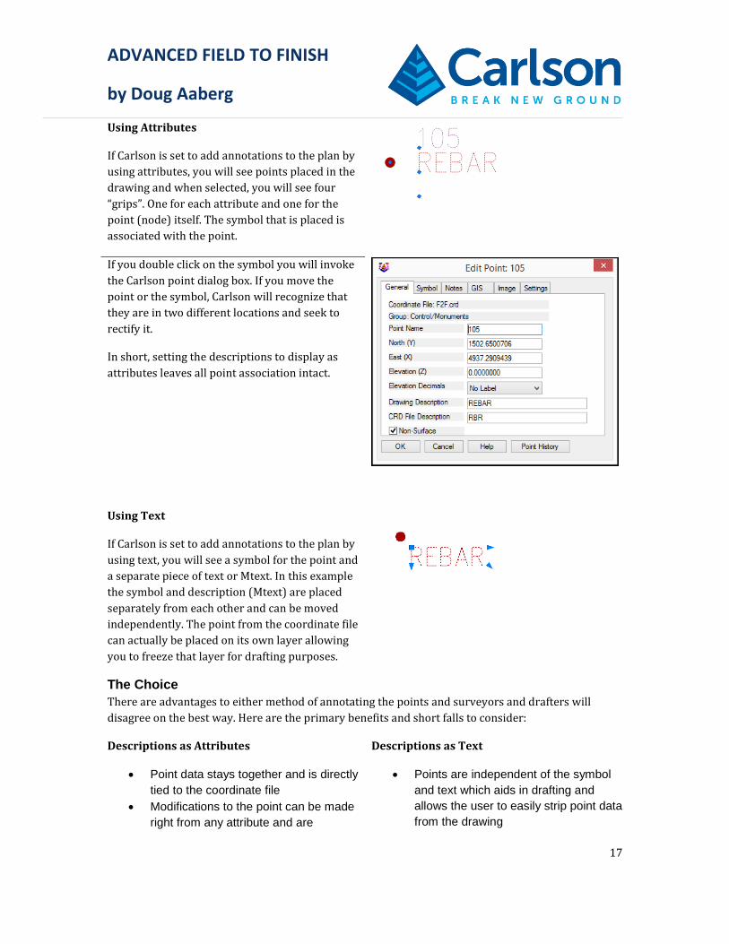
Using Attributes
If Carlson is set to add annotations to the plan by
using attributes, you will see points placed in the
drawing and when selected, you will see four
“grips”. One for each attribute and one for the
point (node) itself. The symbol that is placed is
associated with the point.
If you double click on the symbol you will invoke
the Carlson point dialog box. If you move the
point or the symbol, Carlson will recognize that
they are in two different locations and seek to
rectify it.
In short, setting the descriptions to display as
attributes leaves all point association intact.
Using Text
If Carlson is set to add annotations to the plan by
using text, you will see a symbol for the point and
a separate piece of text or Mtext. In this example
the symbol and description (Mtext) are placed
separately from each other and can be moved
independently. The point from the coordinate file
can actually be placed on its own layer allowing
you to freeze that layer for drafting purposes.
The Choice
There are advantages to either method of annotating the points and surveyors and drafters will
disagree on the best way. Here are the primary benefits and short falls to consider:
Descriptions as Attributes
Point data stays together and is directly
tied to the coordinate file
Modifications to the point can be made
right from any attribute and are
Descriptions as Text
Points are independent of the symbol
and text which aids in drafting and
allows the user to easily strip point data
from the drawing

ADVANCED FIELD TO FINISH
by Doug Aaberg
18
updated in the CRD
Updates to the CRD file such as
elevation datum change, are
immediately updated in the drawing
Moving an attribute using some tools
can potentially alter the coordinates of
the point.
Text or the symbol can easily be
moved without fear of altering the
coordinates of the point
User can easily modify the text and
add unlimited characters using text
wrap etc.
Updating the drawing after a datum
change usually requires reprocessing
through filed to finish.
Both methods have easy to use tools that allow relocating the description. The choice is based on
your work flow, personnel, and type of projects you tend to do.
Exercise: Using Examples of Field to Finish With Attributes
In this exercise you will utilize an FLD file set up to use descriptions as attributes.
1.2.1 Starting a new drawing
1. Select Ribbon: File FIle
New.
2. Select the drawing template CSW-EX.dwt and click <<Open>>.
3. Set the drawing scale to 20
4. Select Set to create and name a new drawing

ADVANCED FIELD TO FINISH
by Doug Aaberg
19
5. Create a new drawing named C:\Carlson Projects\F2F-ATT.dwg
6. Click Save
7. Back in the Startup Drawing Wizard Click Next
8. Ensure the Coordinate File option is set to Existing and click Set to select the coordinate file F2F.crd
9. Click Next to complete the setup
10. From the survey Ribbon select Field to Finish

ADVANCED FIELD TO FINISH
by Doug Aaberg
20
11. From the Draw Field to Finish dialog box, Select Edit Codes
12. From the Field to Finish Code Table editor dialog box, select Code Table Settings

ADVANCED FIELD TO FINISH
by Doug Aaberg
21
13. From the Code Table Settings dialog box, click Set and select the code table CSW-ATT.fld
14. Click OK
Examine the field to finish table CSW-ATT.fld
15. Select the Code AIRON and click Edit

ADVANCED FIELD TO FINISH
by Doug Aaberg
22
Note the settings:
Main layer is set to EX-MONUMENTS. This places the point block itself on that layer
Attribute Format is set to Attribute Block. This means the descriptions as well as the
point number and elevation will all be labeled as an attribute.
Separate Attribute Layers is set to Points. This allows each attribute to be set on its
own specified layer.
Note by clicking on the Set box next to points, another dialog appears allowing you to
manually set each attribute layer. In this example, the symbol layer is irrelevant because the previous
option to separate it was not selected. The symbol therefore will be placed on the main layer.
Point Groups is set to Control\Monuments. This will create a point group with that
name. For those who like to use point groups, this is an easy ay to create them right from
the field data.
Entity Type is set to Points Only. This means you will not automatically be drawing line
work between these points.
Non-Surface is enabled. This means the default condition of all Angle Irons found is to
not be used as part of the surface creation.
16. Click OK
17. Highlight the category Site Feature Lines (3D), select the code BC and click Edit

ADVANCED FIELD TO FINISH
by Doug Aaberg
23
For this code, the option to draw the points on a distinct point layer is used. This allows the user to
keep any point data from being on a layer that will eventually be shown on the final plan.
Description is blank and Use Raw Description is set to Attribute Block. This means
the description will be exactly what was entered in the field. This is helpful when
reviewing line codes etc.
Distinct Point Layer is set to PNT.
Dual 3D Polyline Layer is set to PNT-BREAKLINES
These above settings means that the 2D lines will be drawn on the layer EX-TRV, the points will
be placed on the layer PNT and the 3D polylines (break lines) will be drawn on the layer PNT-
BREAKLINES
Separate Attribute Layers is set to None. Since there will be no points labeled when
drawing line work, there is no need to separate their attributes.
Add text to line work
18. Select the Linetype Tab

ADVANCED FIELD TO FINISH
by Doug Aaberg
24
19. For a Linework Description notice the text BC
20. Click Set
Note that you can modify the layer, text style, text size and control how often the text will be placed
for each type of line.
21. Click OK then OK again to return to the Field to Finish Code Table dialog box
22. Select the code CT and Click Edit
ADVANCED FIELD TO FINISH
by Doug Aaberg
25
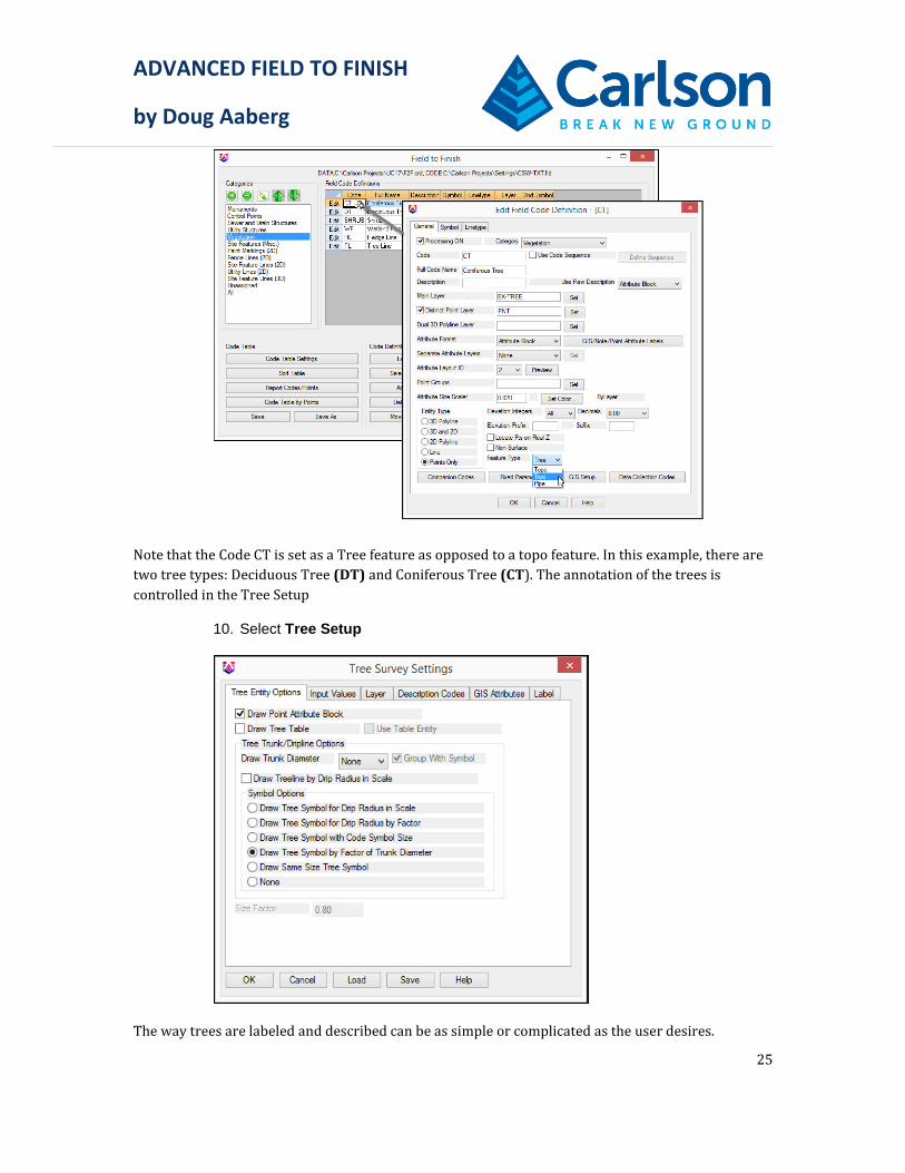
Note that the Code CT is set as a Tree feature as opposed to a topo feature. In this example, there are
two tree types: Deciduous Tree (DT) and Coniferous Tree (CT). The annotation of the trees is
controlled in the Tree Setup
10. Select Tree Setup
The way trees are labeled and described can be as simple or complicated as the user desires.

ADVANCED FIELD TO FINISH
by Doug Aaberg
26
On the Tree Entry Options dialog tab:
Draw Point Attribute Block: Controls whether to draw the point block with the point #, elevation
and description attributes.
Draw Tree Table: This option makes the program prompt for whether to draw a tree table when the
program finds a couple points with tree codes. Otherwise, there must be many tree codes to have the
program prompt for creating a tree table. The Use Table Entity option draws the table as a Carlson
Table Entity. Otherwise the table is drawn with regular CAD lines and text.
Draw Trunk Diameter: Sets whether to create a circle or solid with the trunk diameter. The Group
With Symbol option creates a CAD group to combine the tree and trunk symbols.
Draw Treeline by Drip Radius in Scale: Shrinkwraps the tree driplines to get the overall treeline
perimeter.
Draw Tree Symbol for Drip Radius in Scale: Draws individual symbols for each tree using the
symbols defined in the code table and scaled by the drip size attribute.
Draw Tree Symbol for Drip Radius by Factor: Draws individual symbols for each tree using the
symbols defined in the code table and scaled by the drip size attribute and the Size Factor from this
dialog.
Draw Tree Symbol with Code Symbol Size: Draws individual symbols for each tree using the
symbol name and size defined in the code table.
Draw Tree Symbol by Factor of Trunk Diameter: Draws individual symbols for each tree using the
symbols defined in the code table and scaled by the trunk size attribute multiplied by 12. For
example, a 10" trunk size is drawn as a 10ft symbol.
Draw Same Size Tree Symbol: Draws individual symbols for each tree using the symbols defined in
the code table and at size of 6.
None: Simply does not draw a tree symbol
On the Input Values Options dialog tab:
Default Tree ID to Point ID: This option uses the point number for the tree tag unless the point

ADVANCED FIELD TO FINISH
by Doug Aaberg
27
description contains a tree tag.
Begin Tree ID From: This is the number to start incrementing tree tags from in case the tree coding
is missing tags and you want to assign tags for reporting.
Input Trunk Value: Controls whether the trunk size is entered as a radius or diameter.
Input Drip Value: Controls whether the canopy drip size is entered as a radius or diameter.
On the Layer dialog tab, there are optional layer names for different types of tree entities to append
either as a prefix or suffix to the layer from the code table.

ADVANCED FIELD TO FINISH
by Doug Aaberg
28
On the Description Codes tab, there are settings to help identify the tree attributes in the point
description. The program looks for the trunk size, drip size, tag ID and height in the point description
after the tree code. By default, the program expects the attributes to be in the order of trunk size, drip
size, tag ID and height. Here's an example default order:
OAK 16 12 100 28
where OAK is the tree code from the code table, 16 is the trunk diameter, 12 is the drip radius, 100 is
the tag ID and height is 28.
If the attributes are in a different order, then the suffix/prefix settings can be used to identify the
attributes. When the program finds a specified prefix or suffix, it tells the program which attribute to
use. For example, if the Trunk Suffix is "in" and the Drip Suffix is "ft" and the Tag Prefix is "T", then
OAK T100 16in 12ft
means tag ID of 100, trunk diameter 16 and drip radius 12 feet.

ADVANCED FIELD TO FINISH
by Doug Aaberg
29
In addition to looking for the tree attributes in the point description, the program can also read these
attributes from GIS fields. On the GIS Attributes dialog tab, you can set the GIS field names for the
tree attributes.

ADVANCED FIELD TO FINISH
by Doug Aaberg
30
On the Label tab, there are settings for the tree text labels for the size, offset from trunk center, style
and location. When creating a tree table, only the tag text is labeled. Otherwise, the label is drawn.
Output Trunk Value sets whether to label the trunk size as a radius or diameter.
Output Drip Value sets whether to label the canopy size as a radius or diameter.
The Label Description Setup dialog sets which fields to include in the label or table. For each field,
there are settings for the field order, prefix, suffix and decimals. The New Row option allows for
drawing labels on separate rows. The Header and Width settings are for the tree table.
In this example, the location and description of trees has been kept very simple. A tree will be drawn
either deciduous or coniferous as a point symbol scaled by a factor of the trunk diameter and labeled
with the trunk size with an optional description such as Maple or Oak.
11. Click OK then OK again to return to the Field to Finish Code Table dialog box
Examine many of the other codes to get an idea of how each are set up to work. This of course is all
completely based on user preference and easily modified.
12. Click Exit to exit the Field to Finish Code Table dialog box
13. In the Draw Field to Finish dialog box, ensure all settings are the same as shown above
14. Select Additional Draw Options
15. In the Additional Draw Options dialog box, ensure all the settings are the same as above.
16. In the Additional Draw Options dialog box click OK
ADVANCED FIELD TO FINISH
by Doug Aaberg
31
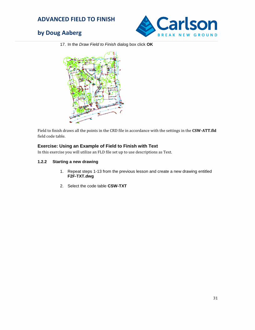
17. In the Draw Field to Finish dialog box click OK
Field to finish draws all the points in the CRD file in accordance with the settings in the CSW-ATT.fld
field code table.
Exercise: Using an Example of Field to Finish with Text
In this exercise you will utilize an FLD file set up to use descriptions as Text.
1.2.2 Starting a new drawing
1. Repeat steps 1-13 from the previous lesson and create a new drawing entitled F2F-TXT.dwg
2. Select the code table CSW-TXT

ADVANCED FIELD TO FINISH
by Doug Aaberg
32
3. Highlight the code AIRON and select Edit

ADVANCED FIELD TO FINISH
by Doug Aaberg
33
Note the settings:
Main layer is set to PNT-MONUMENTS. This places the point block itself on that layer.
The strategy is to create layers for all points and then placing the symbol and text on
separate layers. This allows the user to freeze all point layers or even strip them from the
drawing and still have all the drafting elements needed to complete a plan.
Attribute Format is set to Both. This means the program will place a point containing
attributes as well as creating text for the description.
Separate Attribute Layers is set to Points. This allows each attribute to be set on its
own specified layer. In this example, separate layers are created for monuments and
control points to aid in the preparation of stakeout plans or other types of work sheets.
The majority of the points in the file CSW-TXT are set to be placed on a layer called PNT
4. Select GIS/Note/Point Attribute Labels
This opens the Point Attribute as Text Settings dialog box

ADVANCED FIELD TO FINISH
by Doug Aaberg
34
General Attributes - -In this dialog box you can control which attributes will be labeled by
checking the box next to each.
You can add a prefix or suffix and control the relative position ie. Lower Right along with
the text size and layer.
The section labeled Note and SurvCE GIS Attributes is used for adding custom GIS
attributes as text.
Offset Scalers control the relative position of the text with regards to the point location.
Create as MTEXT aids in modifying the text after it is placed in the drawing
5. Click OK
The tree setup and line work labels are the same as in the previous lesson.
1. Click Exit to exit the Field to Finish Code Table dialog box
2. In the Additional Draw Options dialog box click OK

ADVANCED FIELD TO FINISH
by Doug Aaberg
35

ADVANCED FIELD TO FINISH
by Doug Aaberg
36
1.3 Editing The Plan
In both situations, attribute blocks or text, the plan looks similar. Both options have tools for editing,
moving and adding leaders to labels.
1.3.1 Controlling the plan through layer filters
1. Select the Layer Control
In the layer control dialog box, you can create layer filters and add individual layers to those filters.
This aids in not only limiting the amount of layers displayed, but allows you to freeze, thaw, lock and
isolate those layers.
2. Highlight the layer filter SURVEY POINT DATA and Right Click your mouse
3. Select Visibility then Frozen
1.3.2 Editing with Attributes
Invariably, each plan will need to be edited to address text location, overlaps and duplicates.
1. Zoom to the lower left portion of the drawing

ADVANCED FIELD TO FINISH
by Doug Aaberg
37
2. From the Points Ribbon, select Move Point Attributes with Leader
3. Select a description and pull it to one side or the other
Rotating Symbols
The catch basin/inlet grate is not aligned with the edge of pavement. There are multiple ways to
rectify this including adding a rotation code in field to finish. However, for this example we will rotate
the symbol using the Twist Point Attribute command.
4. From the Points Ribbon, select Twist Point Attribute

ADVANCED FIELD TO FINISH
by Doug Aaberg
38
Follow the prompts:
5. Twist by [Twist screen/Azimuth/<Entity segment>/Follow polyline]? E
6. Attributes to twist [All/<Symbol>/Name/Elevation/Description]? S Deflection angle (0 for parallel, 90 for perpendicular) <0.00>:Enter
7. Pick Line Or Polyline: Select the polyline representing the edge of pavement.
8. Select points from screen, group, or by point number [<Screen>/Group/Number]? S
9. Select Carlson Software points. Select the symbol representing the catch basin inlet grate
Select objects: 1 found
10. Select objects: Enter
Processing 1 of 1
The program rotates the symbol to be parallel
with the polyline selected
Obviously, this function works best if multiple objects are selected. The Follow Polyline option for
example will rotate all selected objects parallel or perpendicular to a complex polyline, such as the
centerline of a road.

ADVANCED FIELD TO FINISH
by Doug Aaberg
39
1.3.3 Editing with Text
One great advantage as far as being able to draft a plan with Carlson is the ability to create simple
CAD objects like symbols and text
11. From the Draft Ribbon, select Move with Leader
Similar to above, the catch basin
label is annotated with a leader.
But since it is Mtext, you can simply
double click on the label and add
any additional text you may like.

ADVANCED FIELD TO FINISH
by Doug Aaberg
40
1.4 Advanced Text Settings
This guide is intended to help you get started using Carlson’s Field to Finish program so you can get
up and running as soon as possible. You should know that there is much more that can be
accomplished with this program. This next lesson explores just some of the more advanced or deeper
settings and functions available.
1.4.1 Adding Text From Field Notes
Often times it is necessary or desired to collect additional information beyond just the elevation and
description. Field to Finish will add any point notes collected in the field. If you are using SurvCE/PC,
you have the ability to add a note to any point right from the field in the data collector.
Any notes added in the field will remain in accessible in a list for easy access later. This is helpful
when adding similar notes to things like utilities for example. You can also set SurvCE to prompt you
for notes as you collect the data.
Alternatively you can add notes from the drawing editor by double clicking on any point and
selecting the Notes Tab.

ADVANCED FIELD TO FINISH
by Doug Aaberg
41
The following steps are for adding notes as text using the CSW-TXT.fld code table. A similar result
can be accomplished using attributes by following a different procedure.
From the drawing editor, 1.double click on point number 102
Select the Notes Tab 2.
Add the text LEANING NE 3.1’ to denote that the concrete monument is leaning 1’ to the northeast.
Click OK 4.
As described above, from the survey Ribbon select Field to Finish 5.
From the Draw Field to Finish dialog box, select Edit Codes 6.
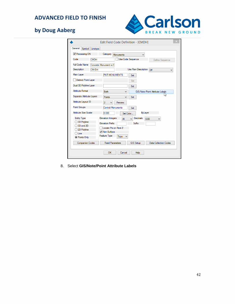
From the Monuments Category select the code CMDH and click EDIT 7.
ADVANCED FIELD TO FINISH
by Doug Aaberg
42
Select GIS/Note/Point Attribute Labels 8.

ADVANCED FIELD TO FINISH
by Doug Aaberg
43
This opens the Point Attributes as Text Settings dialog box. You will see a multitude of options for
adding labels to a point. For this example, ensure that the options are set as shown above.
Of particular note, ensure the following options are set.
General Attributes
Disable all General attributes except Description
Set the Text Size Scaler as 0.08 to be consistent with other labels.
Note and GIS Attributes
Set the Notes option to ALL. This ensures that any note created will be added as text to
the drawing. The other options will be discussed later in this text.
Rotation = 0.0
Position to Lower Right
Text Size Scaler = 0.08
Settings
Offset Scalers set to 0.300. This is the distance the text is placed offset to the position of
the point.
Enable Create as MTEXT
Style = LEROY
Layer = EX-MONUMENTS-TXT
Click OK 9.

ADVANCED FIELD TO FINISH
by Doug Aaberg
44
Following the steps previously described in this manual, reprocess point 10.number 102
The program places the point description and note together as one piece of Mtext. You will also see
each point note listed at the bottom of the dialog box when using Edit Points from the point menu.
1.4.2 Adding Inverts to Sewer Structures
Beyond just adding text to a point in the drawing, Notes can be used to perform other functions
including an equation. In this exercise you will add invert elevations to a sewer manhole by entering
the depth or distance down from the rim.

ADVANCED FIELD TO FINISH
by Doug Aaberg
45
In the above example, the sewer manhole contains three pipes each at a different depth. The task is to
get Carlson to label each invert elevation without manually subtracting each depth from the rim
elevation followed by manually entering text, saving time and helping to eliminate error.
Similar to above, open the Field to Finish editor and select the code SMH and 1.click EDIT
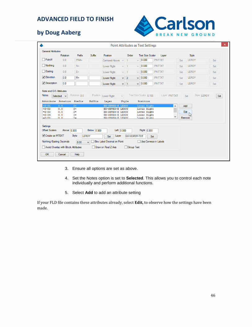
Again, select GIS/Note/Point Attribute Labels 2.
ADVANCED FIELD TO FINISH
by Doug Aaberg
46
Ensure all options are set as above. 3.
Set the Notes option is set to Selected. This allows you to control each note 4.individually and perform additional functions.
Select Add to add an attribute setting 5.
If your FLD file contains these attributes already, select Edit, to observe how the settings have been
made.

ADVANCED FIELD TO FINISH
by Doug Aaberg
47
There are three options in which to specify the note attribute
Sequence# - will set the attribute in the order of the notes entered. You can control the
order of sequence by selecting the sequence number so if the note entry in the field is
different than desired, they can be manipulated
Name – will set the attribute by a specific name. This is useful when collecting GIS
information. For example if a utility pole needed additional information included such as
the number of wires, or material, you could name a note WIRES and another one
MATERIAL
Equation – allows you to use a note to perform a simple equation, add, multiply, subtract
or divide.
In the specify Attribute BY select Equation. 6.
For the equation, type Z-D1. Where Z is the rim elevation (presuming the point 7.located in the field is the rim) and D1 is a user specified value. In this case it stands for Depth number 1.
Note: the user specified value is not restricted in Alpha or numeric characters. You may
specify this part of the equation in any way that makes sense to you and fits into your work flow.
Set the Text Size Scaler to 0.08 8.
For the Prefix, add I= 9.
Set the Position to Lower Right 10.

ADVANCED FIELD TO FINISH
by Doug Aaberg
48
Set the Decimals to 0.00 11.
Set the Layer to EX-SEWER-ELEV 12.
Set the Style to LEROY 13.
Click OK 14.
Repeat this process for 6 potential invert elevations with increasing depth 15.numbers, D2, D3, D4 D5, and D6
Click OK, Save the FLD file and Click Exit 16.
When the Draw Field to Finish dialog box appears, click Cancel. You will 17.return to this step shortly.
From the drawing editor, locate point number 1434 and double click it. 18.

ADVANCED FIELD TO FINISH
by Doug Aaberg
49
Select the Notes Tab 19.
Enter the depth for each 20.invert as shown in the diagram above.
Click OK 21.
From the Survey Ribbon, Select Field to Finish 22.
Click OK 23.

ADVANCED FIELD TO FINISH
by Doug Aaberg
50
You can now use the Move Text with Leader command to reposition the text.
For a more detailed example of using adding notes, watch my video on YouTube:
https://www.youtube.com/watch?v=j1mbsJp635w&t=286s
Using Custom Attributes
If you prefer to accomplish the same task as above but with utilizing attributes, the process is similar
in function and work flow, but different from the point of the initial setup.
This process dictates that you first create a drawing (it works best if this is done in an external
drawing) containing attributes that you would like to add to a point. For the above invert example it
could be a block containing six attributes for inverts.
The next step is to add the new symbol (drawing) to your symbol library. Creating a separate
category for custom symbols is a good idea. You Import the symbol by browsing and selecting it. In
this example I named the drawing containing the inverts, INVERTS.DWG

ADVANCED FIELD TO FINISH
by Doug Aaberg
51
In the Field to Finish editor, you edit the SMH code and in the symbol Tab add the new symbol fro the
symbol library.

ADVANCED FIELD TO FINISH
by Doug Aaberg
52
Click on Custom Attributes and click Find Custom Attributes. The Tags from the attributes contained
in the new symbol are populated into the respective Tag lines. Click set and select Equation from the
drop down selection.
At this point, the process becomes very similar to above. You can add an equation using any custom
notes ie. D1, D2 etc. When you process the point, the inverts are calculated and displayed as part of
the point in the form of an attribute block.
For a more detailed example of using custom attributes, watch my video on YouTube:
https://www.youtube.com/watch?v=Dg-pVkScISI&t=1s