1 basics of hand and finger radiography routine views for fingers include: an a-p (thumb) or p-a (...
TRANSCRIPT

1
Basics of Hand and Finger Radiography
• Routine views for fingers include:
• an A-P (thumb) or P-A ( fingers) view
• an oblique view
• a lateral view
• The digit must be parallel to the film for all projections.

2
12.2 Thumb A-P
• Measure: A-P at Metacarpal-Phalangeal Joint
• Protection: Coat Lead Apron
• SID: 40” Table Top• Film: 1/3 of 10” x 8”
Extremity or Detail Cassette

3
Thumb A-P
• Using Lead Blockers, cover 2/3 of the 10” x 8” Fine or Extremity Cassette
• Center Beam to the uncovered portion of cassette.
• Ask patient to internally rotate arm and place thumb on uncovered portion of cassette.

4
Thumb A-P
• The palm is rolled back to clear the thumb.The palm should not cover the metacarpal or trapezium.
• If overlap is unavoidable, angle tube 10 to 15 degrees cephalad.
• Horizontal CR: metacarpal-phalangeal joint.

5
Thumb A-P
• Vertical CR: long axis of thumb.
• Collimation top to bottom: Tuff of thumb to trapezium.
• Collimation side to side: skin of thumb
• Breathing Instruction: Hold still
• Make exposure and let patient relax

6
Thumb A-P Film
• Thumb should be in a true A-P position. When positioning view look at the thumb nail as a reference.
• Should see from tip of thumb to trapezium. Note the soft tissue overlapping the proximal metacarpal. A tube angle would have improved image.

7
12.2 Thumb P-A Oblique
• Measure: A-P at M-P joint
• Protection: Coat apron• SID: 40” table top• No tube angle• Film: middle 1/3 of 10” x
8” Extremity Cassette• Special equipment: two
lead blockers

8
Thumb P-A Oblique
• Center beam to uncovered portion of the cassette
• Ask patient to place hand on cassette with palm flat on film. The thumb is abducted away from other fingers.
• Horizontal CR: M-P joint• Vertical CR: long axis of
the thumb.

9
Thumb P-A Oblique
• Collimation top to bottom: Tuff of thumb to trapezium
• Collimation side to side: skin of thumb
• Patient Instructions: Remain still
• Make exposure and let patient relax.
10
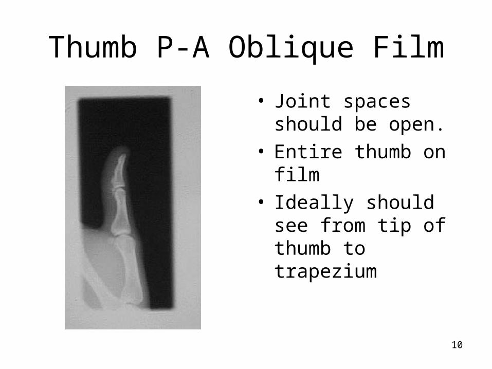
Thumb P-A Oblique Film
• Joint spaces should be open.
• Entire thumb on film• Ideally should see
from tip of thumb to trapezium

11
12.2Thumb Lateral
• Measure: lateral at M-P Joint
• Protection: Coat Apron• SID: 40” Table Top• No tube angle• Film: remaining 1/3 of
the 10” x 8” Extremity or Fine Cassette
• Special equipment: angle sponge

12
Thumb Lateral
• Measure: lateral at M-P Joint
• Protection: Coat Apron• SID: 40” Table Top• No tube angle• Film: remaining 1/3 of
the 10” x 8” Extremity or Fine Cassette
• Special equipment: angle sponge

13
Thumb Lateral
• Cover 2/3 of cassette with lead blockers. Center beam to remaining 1/3 of cassette.
• Sponge is placed on covered portion of the cassette.
• Patient is asked to place palm on sponge with thumb on unexposed portion of film.

14
Thumb Lateral Film
• The thumb should be in true lateral position.
• Joint spaces open• Must see from tip of
thumb to trapezium.• Lateral view is best
view for marker.

15
Thumb Series Film
• Joint spaces open
• Must see from tip of thumb to trapezium.
• Lateral view is best view for marker.

16
Better Thumb Series
• Fracture at base of 1st metacarpal seen with tube angle is to move soft tissue of palm on A-P view.
• The trapezium is seen on all three views.

17
12.3 Finger P-A
• Measure: P-A at PIP joint
• Protection: Coat apron• SID: 40” Table Top• Film: 1/3 of 10” x 8”
detail, fine or extremity cassette
• Special equipment: Lead Blockers

18
Finger P-A
• Cover 2/3 of cassette with lead blockers
• Center beam to uncovered portion of cassette.
• Patient asked to place affected finger on uncovered portion of cassette. The palm and finger flat on film.

19
Finger P-A• Horizontal CR: PIP joint
• Vertical CR: long axis of finger
• Collimation top to bottom: Tip of affected finger to M-P joint.
• Collimation side to side: slightly larger than skin of finger
• Patient instructions: remain still
• Make exposure and let patient relax

20
Finger P-A
• Include entire finger from tip to M-P Joint
• Joint spaces must be open.
• With crooked or bent finger, A-P may be helpful,

21
12.3Finger Oblique View
• Measure: A-P at PIP joint
• Protection: Coat apron• SID: 40” table top• No tube angle• Film: middle 1/3 of 10”
x 8” cassette. Cover remainder of cassette with lead blockers.
• Special Equipment: 45 degree sponge or step sponge

22
Finger Oblique View
• Place sponge on cassette.
• Ask patient to place hand on sponge with ulnar side to film. Hand will be at a 45 degree angle to film.
• Make sure that the affected finger is parallel to film. The step sponge is designed to keep finger parallel to film.

23
Finger Oblique View
• Center the affected finger to unexposed portion of film.
• Horizontal CR: PIP of the affected finger
• Vertical CR: long axis of affected finger
• Ask patient to remain still while making exposure.
24
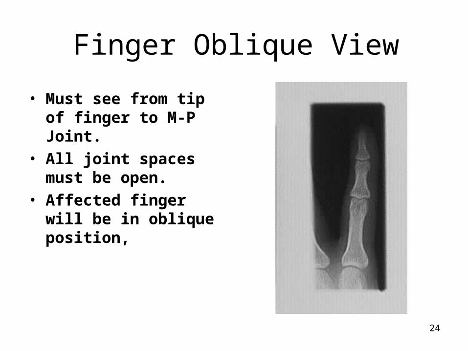
Finger Oblique View
• Must see from tip of finger to M-P Joint.
• All joint spaces must be open.
• Affected finger will be in oblique position,

25
12.3 Finger Lateral View
• Measure: Lateral at PIP of affected finger
• Protection: Coat Apron• SID: 40” table top• No tube angle• Film: remaining 1/3 of
10” x 8” Extremity Cassette

26
Index Finger Lateral
• Index finger: Radial side of hand next to film with index finger extended. Other fingers bent out of the view.
• Horizontal CR: PIP of index finger
• Vertical CR: long axis of finger

27
Finger Lateral
• Collimation top to bottom: tip of affected finger to M-P joint
• Collimation side to side: slightly larger than skin of finger
• Patient Instruction: Remain still
• Make exposure and let patient relax

28
Third Finger Lateral
• Third finger: Radial side of hand next to film with third finger extended and resting on sponge. Other fingers bent out of the view.
• Horizontal CR: PIP of third finger
• Vertical CR: long axis of finger

29
Fourth Finger Lateral
• Fourth finger: Ulnar side of hand next to film with fourth finger extended and resting on sponge. Other fingers bent out of the view.
• Horizontal CR: PIP of fourth finger
• Vertical CR: long axis of finger

30
Fifth Finger Lateral
• Fifth finger: Ulnar side of hand next to film with fifth finger extended and resting on sponge. Other fingers bent out of the view.
• Horizontal CR: PIP of fifth finger
• Vertical CR: long axis of finger

31
Finger Lateral
• Joint spaces must be open. They will not be open if finger is not parallel to film.
• Must see from tip of the affected finger to the Metacarpal-Phalangeal Joint.

32
Finger Series
• Joint spaces must be open. They will not be open if finger is not parallel to film.
• Must see from tip of the affected finger to the Metacarpal-Phalangeal Joint.

33
12.4 Hand P-A
• Measure: A-P at 3rd M-P joint
• Protection: Coat Apron• SID: 40” table top• No tube angle• Film: 1/2 of 12” x 10” or
30 cm x 24 cm Extremity Cassette

34
Hand P-A
• Cover 1/2 of cassette with Lead Blocker
• Center beam to uncovered half of cassette.
• Ask patient to place hand flat on cassette. Fingers are spread slightly.
• Horizontal CR: third M-P joint

35
Hand P-A• Vertical CR: long axis of
hand• Collimation top to
bottom: tips of fingers to 1” of distal ulna and radius
• Collimation side to side: skin of hand and fingers
• Instruction patient to remain still.
• Make exposure and let patient relax

36
Hand P-A
• View should include all fingers, metacarpals, carpal bone and one inch of the distal ulna and radius.
• Fingers are spread slightly to avoid superimposed soft tissues.

37
12.5 Hand P-A Oblique
• Measure: A-P at metacarpal-phalangeal joints
• Protection: Lead Apron• SID: 40” Table Top• No Tube Angle• Film: 1/2 of 12” x 10” or
30 cm x 24 cm detail or extremity cassette

38
Hand P-A Oblique
• The unexposed portion of the film used for the P-A hand will be used.
• Using a special stepped sponge or other suitable sponge, place hand with ulna side to the film.
• Hand should form a 30 to 45 degree angle with fingers parallel to film.

39
Hand P-A Oblique
• Horizontal CR through the metacarpal - phalangeal joints.
• Vertical CR: between the second and third MP Joints
• Collimation top to bottom: Tips of fingers to 1” of distal radius
• Collimation side to side: skin of hand and fingers

40
Hand P-A Oblique
• Make sure that all fingers are within the collimated field. Need to also include the distal ulna and radius.
• Ask patient to remain still and make the exposure.
• Let patient relax

41
Hand P-A Oblique
• The P-A and Oblique hand views are taken on the same film.
• Make sure that all joints in the phalanges are open.
• Distal ulna and radius should be seen
• All soft tissue of the hand should be imaged.

42
12.6 Hand Lateral
• Measure: Lateral at Metacarpal Phalanges Joints
• Protection: Coat Apron• SID: 40” Table Top• Film: 8” x 10” Extremity
or detail Cassette• Special Equipment:
Lateral Hand Sponge

43
Hand Lateral
• Hand placed in a lateral position with ulna to film.
• Lateral hand sponge placed next to hand. Patient will spread fingers so each finger will rest on the appropriate step of sponge.
• Or

44
Hand Lateral
• Hand placed on film in lateral position with ulna to film.
• Patient makes the “OK” sign with fingers. Keep each finger parallel to film.
• Horizontal CR: 2nd MP joint.

45
Hand Lateral
• Vertical CR: long axis of hand.
• Collimation: to include all fingers and distal one inch of forearm.
• Instructions: Hold still • Make exposure and let
patient relax.

46
Hand Lateral Film
• Hand and wrist should be in lateral position.
• Distal forearm and metacarpal will be superimposed
• Fingers spread with joint spaces open.
• To avoid over exposing the fingers, a #3 point filter was used.

47
Wrist Radiography
• Examinations tailored to the history and mode of injury.
• Routine views are P-A, Oblique & Lateral
• If scaphoid injury is suspected add the Ulna deviation and/or P-A scaphoid.
• If ligament problem is suspected, the A-P clinched fist view is taken.

48
Wrist Radiography
• When there is a possibility of a fracture of the distal radius, an A-P and A-P oblique view may be very helpful.

49
Distal Radius Fracture
• P-A A-P• The A-P provides a better view of the distal radius

50
Surgical repair of fractured scaphoid

51
12.7 Wrist P-A
• Measure: A-P through carpal bones
• Protection: Coat Apron• SID: 40” Non-Bucky• Film: 1/4 or 1/3 of a
10”x12” Extremity or Detail Cassette. Dividing cassette into quarters is recommended.

52
Wrist P-A
• Cover unused portions of cassette with lead shields. Center beam to 1/4 of cassettes uncovered.
• Ask patient to rest wrist in P-A position on cassette.
• Ask patient to cup fingers to move carpal bones closer to the film.

53
Wrist P-A
• Horizontal CR: Just distal to radius or through the first row of carpal bones.
• Vertical CR: long axis of wrist ( mid way between ulna and radius and third metacarpal).

54
Wrist P-A
• Collimation top to bottom: less than 1/4 of the 10” x 12 or from carpal to metacarpal articulations to include distal ulna and radius.
• Collimation side to side: soft tissue of wrist
• Ask patient to hold still and make exposure.

55
Wrist P-A Film
• Must include all carpal bones and wrist soft tissue.
• Articulations with metacarpals and distal ulna and radius must be seen.
• Don’t cut off too much of the distal ulna and radius.

56
12.8 Wrist P-A Oblique
• Measure: A-P at carpal bones
• Protection: Lead Apron
• SID: 40” table top• No Tube Angle• Film : 1/4 of the 24cm x
30cm detail or fine cassette
• Accessories: Sponge and Lead Blockers

57
Wrist P-A Oblique
• Cover the exposed quarter of cassette. Uncover the next quadrant of the cassette.
• Center beam to this section of the cassette.
• Ask patient to place wrist in this section.The wrist is rotated to a 35 - 45 degree oblique with ulna resting on film.

58
Wrist P-A Oblique
• The thumb may be extended to rest on the film for support.
• The wrist can be placed on a sponge with the fingers wrapped over the end of the sponge.
• Horizontal CR: first row of carpal bones or slightly distal to the radius.

59
Wrist P-A Oblique
• Vertical CR: middle or the wrist or aligned between the second and third metacarpals and long axis of ulna and radius.
• Collimation side to side: soft tissue of wrist
• Collimation top to bottom: must include the articulations with metacarpals and distal radius.
60
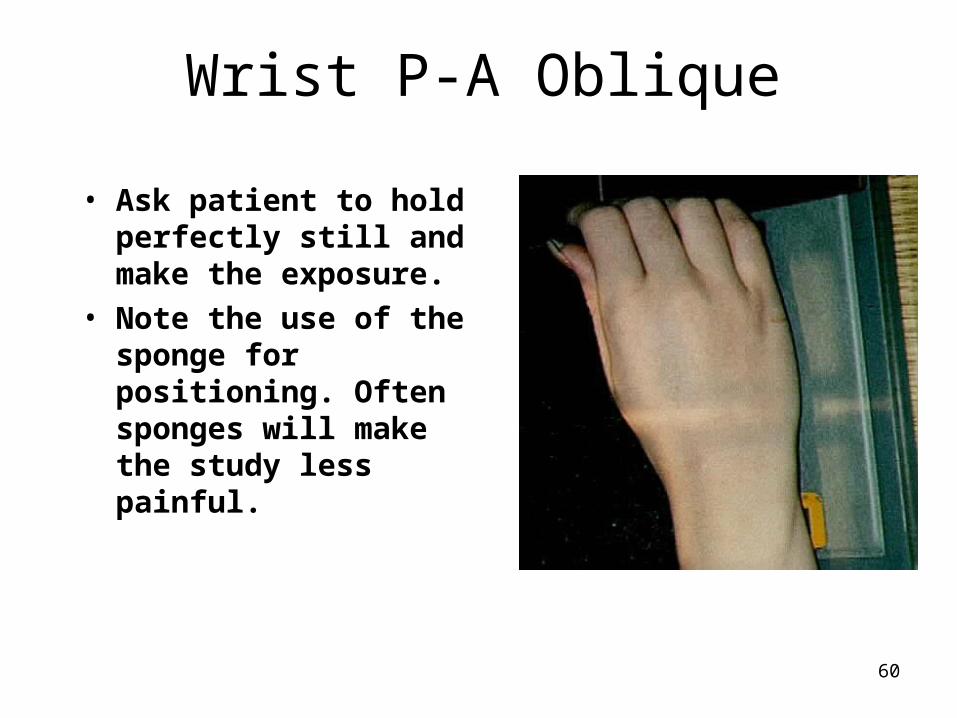
Wrist P-A Oblique
• Ask patient to hold perfectly still and make the exposure.
• Note the use of the sponge for positioning. Often sponges will make the study less painful.

61
Wrist P-A Oblique Film
• The trapezium and trapezoid carpal bones should be seen clear of superimposition.
• The scaphoid tuberosity will be seen.
• This view demonstrates the correct placement of the central ray.
• Adequate visualization of the distal radius is achieved.

62
12.9 Wrist Lateral View
• Measure: Lateral through carpal bones
• Protection: Lead apron• SID: 40” table top• No tube angle• Film: 1/3 or 1/4 of 24 cm
x 30 cm or 10” x 12” detail or extremity cassette

63
Wrist Lateral View
• The patient is seated or kneeling next to the table.
• The next section of the unexposed portion of the cassette is uncovered and the exposed film covered by blockers.
• The beam is centered to the uncovered portion of the film.

64
Wrist Lateral View
• The patient is asked to place their wrist on the film.
• The entire forearm should be in a lateral position with the elbow bent 90 degrees.
• The fingers are cupped or may remain straight with the thumb to the side.

65
Wrist Lateral View
• Horizontal CR: the first row of carpal bones or about 1 cm distal to the radius.
• Vertical CR: long axis of wrist and forearm/
• Collimation: skin of wrist and to include distal radius to metacarpal- carpal joints.

66
Wrist Lateral View
• The lateral view is the best view to place the anatomical marker.
• Make sure it is within the primary beam.
• Ask patient to remain still and make exposure.
• Let patient relax. If no scaphoid film is needed, process the film.

67
Wrist Lateral Film
• The distal ulna and radius should be superimposed indicating no rotation.
• The distal end of the scaphoid and pisiform will be superimposed.
• The first metacarpal should be off to the side.

68
12.10 Wrist P-A for Scaphoid
• Measure: A-P through carpal bones
• Protection: Lead Apron• SID: 40” Table Top• Tube angle: 15 to 20
degrees cephalad or sponge placed under wrist
• Film: 8” x 10” Detail or Extremity Film

69
Wrist P-A for Scaphoid
• Sponge and no angle method.
• A 15 degree sponge is placed on the cassette.
• Patient places palm of the hand on the sponge. The palm will be at a 15 to 20 degree angle to the film.

70
Wrist P-A for Scaphoid
• Tube angle method.• Tube is angled 15 to 20
degrees cephalad and centered to film.
• Patient asked to place wrist flat on the film.
• Tube angle and sponge methods:
• Horizontal CR centered to scaphoid or about 0.5” distal to the radial styloid process

71
Wrist P-A for Scaphoid
• Tube angle and Sponge method.
• Vertical CR: centered to scaphoid or mid wrist
• Collimation: soft tissue of wrist
• Ask patient to remain still and make exposure.

72
Wrist P-A for Scaphoid Film
• The scaphoid will be elongated making it easier to visualize fractures.
• Joint spaces around scaphoid should be open.
• Distal ulna and radius must be seen.

73
12.11 Wrist Unlar Flexion for Scaphoid
• Measure: A-P through carpal bones
• Protection: Coat Apron• SID: 40” Non-Bucky• Tube angle: 15 to 20
degrees cephalic• Film: 1/4 of a 10”x12” or
on a 8” x 10”Extremity or Detail Cassette.

74
Wrist Ulnar Flexion
• Cover unused portions of cassette with lead shields. Center beam to 1/4 of cassettes uncovered.
• Ask patient to rest wrist in P-A position on cassette.
• Ask patient to unlar flex their wrist as far as they can tolerate.

75
Wrist Ulnar Flexion
• Horizontal CR: Through the scaphoid or slightly distal to the radius.
• Vertical CR: Through the scaphoid or very slightly medial to the long axis of the wrist. If patient is small, center to the distal forearm.

76
Wrist Unlar Flexion
• Collimation top to bottom: less than 1/4 of the 10” x 12 or from carpal to metacarpal articulations to include distal ulna and radius.
• Collimation side to side: soft tissue of wrist
• Ask patient to hold still and make exposure.

77
Wrist Unlar Flexion Film
• The scapholunate and scaphocapitate spaces should be open.
• If scaphocapitate space is closed, oblique the wrist about 15 degrees.
• Hand must be flat on film to open the scaphotrapzium joint space.

78
12.12 Wrist A-P Stress View
• Measure: A-P through carpal bones
• Protection: Coat Apron• SID: 40” Non-Bucky• Film: 1/4 of a 10”x12”
with routine wrist series or individual 8” x 10” Extremity or Detail Cassette.

79
Wrist A-P Stress
• Cover used portions of cassette with lead shields. Center beam to 1/4 of cassettes uncovered.
• Ask patient to rest wrist in A-P position on cassette.
• Ask patient to form a fist. Make sure that wrist is not in a oblique position.

80
Wrist A-P Stress View
• Horizontal CR: Just distal to radius or through the first row of carpal bones.
• Vertical CR: long axis of wrist ( mid way between ulna and radius and third metacarpal).

81
Wrist A-P Stress View
• Collimation top to bottom: less than 1/4 of the 10” x 12 or from carpal to metacarpal articulations to include distal ulna and radius.
• Collimation side to side: soft tissue of wrist
• Ask patient to clinch their fist and hold still and make exposure.

82
Wrist A-P Stress Film
• Must include all carpal bones and wrist soft tissue.
• The view is to stress the ligaments in the wrist.
• The first row of carpal should form a “C” on the normal view.

83
19.1 Quality Assurance and Quality Control
• Q A is a management tool used to optimize the performance of radiography services.
• If we can optimize the performance of taking radiographs and assure that the equipment is operating properly, the office will operate more efficiently.
• Your patient will receive better care and lower exposure to radiation.

84
Quality Assurance and Quality Control
• Elements of a QA Program:• Policies and Procedures that establish
standards for training, performance and competency of staff.
• Defined administrative accountability and standards

85
Quality Assurance and Quality Control
• Elements of a QA Program:• A Quality Control Program for x-ray, film
processing and ancillary equipment.
• Preventive and corrective maintenance of the equipment.
• Retake or repeat rate analysis to quantity competencies and control of radiography.

86
Quality Control in Radiography
• Definition:• Standardized test of the equipment at
prescribed intervals designed to detect slowing evolving problems before they cause significant deterioration of image quality.

87
Quality Control in Radiography
• Q C Tests of three Groups of Equipment:
• Dark room, Film Storage and Processing
• Radiographic Equipment and calibration
• Accessories including cassettes, grids and radiation protection devices.

88
Quality Control in Radiography
• Costs Associated with a QA Program:
• Training of Staff
• QC equipment (about $2,000)
• Lost treatment time if done during patient visit times.
• Costs of physicist or specialist to test equipment.

89
Quality Control in Radiography
• Benefits Associated with a QA Program:
• Reduced repeated films, better throughput and lower radiation exposure for your patient.
• Lower cost from waste of film, processing chemicals and hazardous waste.
• Less wear and tear on equipment.

90
Quality Control in Radiography
• Benefits Associated with a QA Program:
• Overall reduced service cost on equipment
• Ability to combine QA with radiation and office safety programs to meet regulatory requirements.

91
Four Major Steps of QA
• Acceptance testing to insure that equipment meets specifications.
• Establishing baseline of equipment performance.
• Diagnosis of changes in performance of equipment
• Verification of corrective measures.

92
Retake Analysis
• Done every three months using a relatively large sample of data to see trends in:– Type of examination being repeated.– Reasons for the repeated films.– Determine if additional training or review is
needed.– Determine if equipment service might be
required.

93
Equipment needed for Q C
The Aluminum Step Wedge is used to test the dark room safelight and consistency of exposure.

94
Equipment needed for Q C
A homogenous phantom. The lead apron may be used as a homogenous phantom or a piece of Lucite may be used.

95
Equipment needed for Q C
Wire mesh test tool used to test cassette screen contact.

96
Equipment needed for Q C
Thermometer used to measure processor chemical temperatures.

97
Equipment needed for Q C
Sensitometer used to generate a highly reproducible stepwedge for processor quality control..

98
Equipment needed for Q C
Densitometer used to measure the amount of light passing through an exposed film.

99
Darkroom Quality Assurance Rules
1. No food or drink or smoking in the dark room.
2. Daily cleaning of dark room to avoid dust.
3. Daily cleaning of dark room work surfaces.
4. Handle film with clean and dry hands. 5. Check that the safelight is equipped with
the correct filter and bulb.

100
Darkroom Quality Assurance Rules
6. Keep cassettes and screens clean and free of artifacts.
7. Load only one sheet of film in cassettes. 8. Handle film carefully to avoid artifacts.
Use clean and dry hands and touch only the edges of the film.
9. Lock the darkroom door when processing or loading film into the cassettes.

101
X-Ray Quality Assurance Rules
1. Measure patient with calipers. 2. Consult technique chart and record
factors used to take film. 3. Enter correct technical factors in
control. 4. Accurate and precise positioning of
patient and equipment. 5. Collimate beam to area of interest or
less than films size,whichever is smaller.

102
X-Ray Quality Assurance Rules
6. Give concise and accurate breathing instructions to patient and ask patient to remain still.
7. Observe patient for compliance with instructions before making exposure.
8. Hold exposure button down for complete exposure.

103
End of Lecture
Return to Lecture Index
Return to Rad Tech 2 Home Page