1 chapter 2: light on- lights off presentation based on: "what's a microcontroller ?"...
TRANSCRIPT

1
Chapter 2: Light on- Lights Chapter 2: Light on- Lights offoff
Presentation based on:
"What's a Microcontroller ?"By Andy LindsayParallax, Inc
Presentation developed by:Presentation developed by:
Martin A. HebelMartin A. HebelSouthern Illinois University CarbondaleSouthern Illinois University CarbondaleCollege of Applied Sciences and ArtsCollege of Applied Sciences and ArtsElectronic Systems TechnologiesElectronic Systems Technologies9/02/03

2
Presentation IndexPresentation Index
Use and Copyright Indicator LightsThe LED as a LightVoltage and CurrentOhm's LawThe ResistorLEDsBreadboard AreaActivity #1 Building and Testing the Light
Circuit
Continued on next Slide

3
Activity #2: On/Off Control With the BASIC Stamp
Sequential Flow & LoopingPseudo-Code & FlowchartsWhere's the program?Activity #3: Counting and RepeatingVariablesActivity #4: Second LED Circuit.Activity #5: Using a Bi-Color LEDChapter 2 ReviewLinks

4
Use and CopyrightUse and Copyright
This presentation supplements "What's a Microcontroller" by Andy Lindsay. (Link to text)
This presentation is not a replacement for the text.
Important concepts of the text are highlighted. In some cases, additional material has been
added to augment the text. Denoted by titles colored goldgold.
Full program listings are generally not provided in the presentation.
Distribution:This presentation may be freely distributed without
modifications. Modifications are permitted by schools and organizations for internal use only. Credits, use and copyright slides must remain.

5
COPYRIGHTS AND TRADEMARKSThis documentation is Copyright 2003 by Parallax, Inc. By downloading or
obtaining a printed copy of this documentation or software you agree that it is to be used exclusively with Parallax products. Any other uses are not permitted and may represent a violation of Parallax copyrights, legally punishable according to Federal copyright or intellectual property laws. Any duplication of this documentation for commercial uses is expressly prohibited by Parallax, Inc. Check with Parallax for approval prior to duplicating any of our documentation in part or whole for any use.
BASIC Stamp is a registered trademark of Parallax, Inc. If you decide to use the name BASIC Stamp on your web page or in printed material, you must state that "BASIC Stamp is a registered trademark of Parallax, Inc." Other brand and product names are trademarks or registered trademarks of their respective holders.
DISCLAIMER OF LIABILITYParallax, Inc. and Southern Illinois University are not responsible for special,
incidental, or consequential damages resulting from any breach of warranty, or under any legal theory, including lost profits, downtime, goodwill, damage to or replacement of equipment or property, or any costs of recovering, reprogramming, or reproducing any data stored in or used with Parallax products. Parallax is also not responsible for any personal damage, including that to life and health, resulting from use of any of our products. You take full responsibility for your BASIC Stamp application, no matter how life threatening it may be.
6
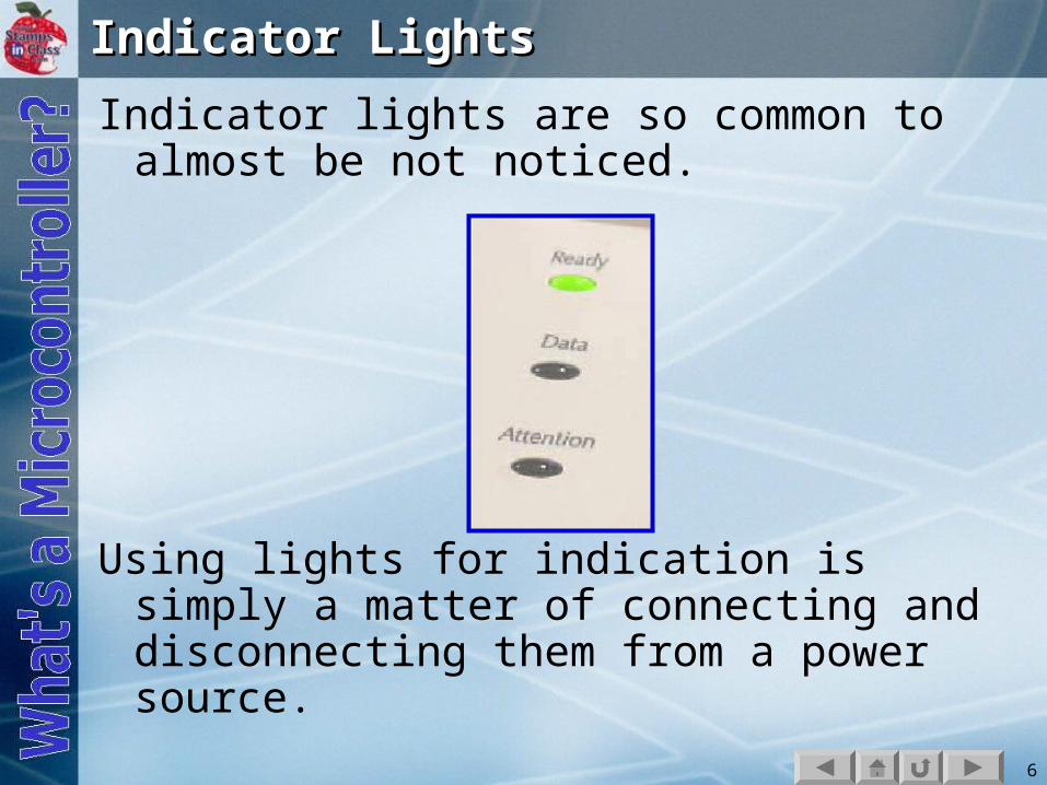
Indicator LightsIndicator Lights
Indicator lights are so common to almost be not noticed.
Using lights for indication is simply a matter of connecting and disconnecting them from a power source.

7
The LED as a LightThe LED as a Light
An LED (pronounced L-E-D), Light Emitting Diode, is a very popular choice as an indicator light because of its low power use and extremely long life.
It is quite simple to control with the low voltage of the BASIC Stamp but requires:
A resistor to limit the current.Being connected in the correct
orientation.

8
Voltage and CurrentVoltage and Current
Voltage and current can be compared to water pressure and flow. When the valve is opened, what will happen? What determines how fast the water will flow?

9
Of course water will flow from the fuller tank because it has greater pressure than the empty tank.
The flow rate is dependent on:The difference in pressure between the
two tanks.The amount of restriction to flow in the
pipe and valve.
The water that flows from your facet is dependent on the height of your town's water tank, the size of the pipes, and how far you open the faucet.

10
In a battery, there is surplus of electrons on one side, and a deficiency of electrons on the other side (holes).
When a circuit is completed, such as putting an LED in it, a flow exists from one side to the other. This is called Current.

11
Current can be viewed in one of 2 ways:Electron Flow: Electrons flow from the
negative side(-) to the positive side.OR
Hole Flow or Conventional Flow: Holes, or the absence of electrons, move from positive to negative as the electrons move.
++++-- -- -- ++---- -- ++ --++-- ++ -- ++--++ -- ++
Electrons (-)Electrons (-)
Holes (+)Holes (+)An atom with an An atom with an excess of electrons excess of electrons has a – charge. One has a – charge. One with a deficiency of with a deficiency of electrons has a + electrons has a + charge.charge.

12
Which version of flow is used doesn't matter. How much flows does. Just as with the water tanks:
The greater the pressure, or the difference in potential (Voltage), the greater the amount of current that can flow in a unit time (Amperes).
The greater the restriction to flow (Ohms), the lower the amount current that can flow.

13
Ohm's LawOhm's Law
Ohms Law states: The amount of current (I) that will flow is proportional to the voltage applied (V), and inversely proportional to the resistance (R) of the circuit.
I = V/R
As Resistance increases, current decreases.

14
LEDs have minimal resistance to current flow. A 5 volt source can destroy an LED if current is not restricted. From Ohm's Law, if R is 1 , how much current will try to flow? An LED drops approximately 1.4V, leaving 3.6V.
I = (5V-1.4V)/1 = 3.6 A
The maximum current a typical LED can handle is around 30mA, or .030 A.
15
The ResistorThe Resistor
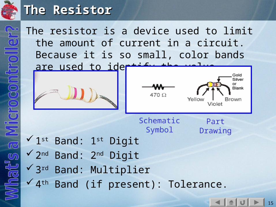
The resistor is a device used to limit the amount of current in a circuit. Because it is so small, color bands are used to identify the value.
1st Band: 1st Digit2nd Band: 2nd Digit3rd Band: Multiplier4th Band (if present): Tolerance.
SchematicSymbol
PartDrawing

16
For the resistor shown:Yellow = 4, 1st DigitViolet = 7, 2nd DigitBrown = 1, add 1 zero.470 Ohm or 470
Tolerance is how far off itcould be from the labeledvalue:Gold: 5%Silver: 10%none: 20%

17
Using the 470 resistor in series with the LED, how much current will be able to flow with a 5V source?
(5V-1.4V)/470 = 0.0077 Amps or 7.7mA

18
What is the resistance of a resistor colored Brown-Black-Orange? (Click slide for answer)
Answer: Brown = 1, Black = 0, Orange = 31, 0 , + 3 zeros = 10,000 ohms or 10K Ohm

19
LEDsLEDs
A Diode is light a one-way check valve in that current can flow in only one direction. An LED is a diode that emits light as current is passed through it (Light Emitting Diode).
Note the connections on the LED:
Anode: Connected to + side ofvoltage. Typically has a longer lead.
Cathode: Connected to – side of voltage. Typically has a shorter lead AND a flat portionon the lens.
20
Breadboard AreaBreadboard Area
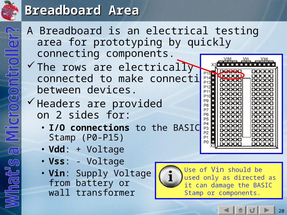
A Breadboard is an electrical testing area for prototyping by quickly connecting components.
The rows are electrically connected to make connectionsbetween devices.
Headers are providedon 2 sides for:• I/O connections to the BASIC
Stamp (P0-P15)• Vdd: + Voltage• Vss: - Voltage• Vin: Supply Voltage
from battery or wall transformer
Use of Vin should be used only as directed as it can damage the BASIC Stamp or components.

21
Example connections of devices. Do Not Build. Note how the rows of sockets make complete paths of current between devices and from I/O headers and Vdd or Vss.

22
Activity #1 Building and Testing the Light Activity #1 Building and Testing the Light CircuitCircuit
Construct the circuit per your text.As the current path from Vdd(+) to Vss(-)
is completed, the LED will light.
What happens if the LED is reversed?What happens if a 1K ohm resistor is
used?

23
What happens when both sides are connected to the same supply? With no difference in potential (electrical pressure), no current will flow, and the LED will not light.

24
Activity #2: On/Off Control With the BASIC Activity #2: On/Off Control With the BASIC StampStamp
With the BASIC Stamp the Input/Output pins (P0-P15) are controlled to supply either the Vdd (+) or Vss (-) potential. This will control whether a device has a path for current to flow or not.

25
Connect the circuit per your text.

26
Enter the code to control and run per the text:

27
The LED should be flashing on and off once per second.
Key Commands:• HIGH 14: Places I/O pin P14 High. This
correlates to 5V or Vdd (digital 1). Current flows between P14 and Vss energizing the LED.
• PAUSE 500: BASIC Stamp pauses operation for the specified time in milliseconds. 500 milliseconds = 0.5 seconds
• LOW 14: Places I/O pin P14 Low. This correlates to 0V or Vss (digital 0). Current does not flow between P14 and Vss, LED is not energized.
• DO and LOOP: Creates a looping structure for repetition.

28
Sequential Flow & LoopingSequential Flow & LoopingSequential Flow: Computer programs
generally start at the 'top' of the program or routine and progress line by line executing each instruction.
Looping: An instruction causes execution to branch to an earlier point.

29
Pseudo-Code & FlowchartsPseudo-Code & Flowcharts
As programs become more complex, programming tools are beneficial in the planning of the code.
Pseudo-Code: Descriptive statements to describe what the program will do.
Flowcharts: Graphical representation of what the program will do.

30
Pseudo-Code ExamplePseudo-Code Example
An example of Pseudo-Code for the LED on/off program may be:
1. Start2. Turn on LED3. Wait for ½ second4. Turn off LED5. Wait for ½ second6. Go back to start
A program for this pseudo-code could be written in any number of computer languages.

31
FlowchartsFlowcharts
Flowcharts use symbols to represent the type of action that is taking place at each step of a program, and graphically illustrate the flow.
Oval - Start/Stop: Beginning or end of a program or routine.
Rectangle - Process: Indicates a process being performed that is internal to the controller/ computer.
Parallelogram – Input/Output: Indicates reading an input or controlling an output.
Diamond – Decision: The state of a condition is checked, and execution branches to 1 of 2 directions based on the result – True or False.
32
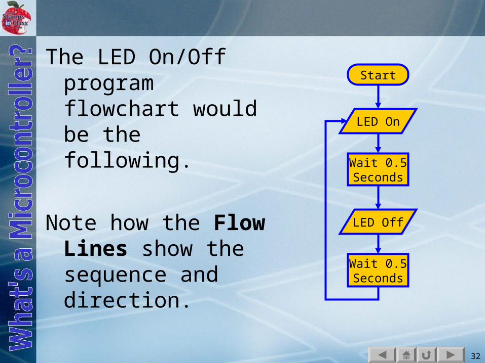
The LED On/Off program flowchart would be the following.
Note how the Flow Lines show the sequence and direction.
Start
LED On
Wait 0.5Seconds
LED Off
Wait 0.5Seconds

33
Where's the program?Where's the program?
Now that the LED is blinking per the program, test this:
Disconnect the serial cable from the BASIC Stamp. What happens? Why?
Turn off power to your BASIC Stamp… count to 10… turn it back on. What happens? Why?

34
The program was transmitted to the BASIC Stamp, stored in a permanent memory (EEPROM-- programmable, non-volatile ROM) and the computer is no longer required.
The BASIC Stamp could now be placed into some device to become Embedded Control for the device.
A program CANNOT be retrieved from a BASIC Stamp, so make sure you save yours!

35
What happens as the arguments for the PAUSE instructions are changed?
What happens if the DO and LOOP instructions are commented out (placing apostrophes in front of them)?

36
Activity #3: Counting and Activity #3: Counting and RepeatingRepeatingCounting and making decisions based
on a value are key components to many programs.
It is desired to make the LED blink 10 times through looping and then stop. Consider the pseudo-code and flowchart on the next slide.

37
Flow for LED On-Off 10 timesFlow for LED On-Off 10 times
1. Start2. Begin count at 13. Turn LED On4. Pause ½ second5. Turn LED off6. Pause ½ second7. Increment count8. Count < 10?
True, loop back to step 4
9. End Program
Start
LED On
Wait 0.5 Sec
LED Off
Wait 0.5 Sec
Counter = 1
Add 1 to Counter
Counter<= 10
End
True
FalseThe diamond decision symbol evaluates Counter and flow branches one of two directions based on the result.

38
Using a DO-LOOP WHILEUsing a DO-LOOP WHILE
One way the code could be written is to use a DO-LOOP WHILE structure. The Loop will continue as long as the condition of Counter <= 10 is true. This is a Conditional Loop.
Note that the counter is:
InitializedUpdatedChecked
What is the value of Counter when the loop is complete? 11.
39
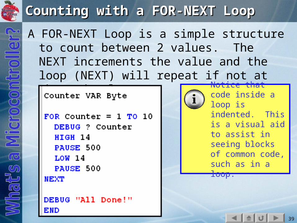
Counting with a FOR-NEXT LoopCounting with a FOR-NEXT Loop
A FOR-NEXT Loop is a simple structure to count between 2 values. The NEXT increments the value and the loop (NEXT) will repeat if not at the end value.
Notice that code inside a loop is indented. This is a visual aid to assist in seeing blocks of common code, such as in a loop.

40
Code with full comments:
The flowchart and pseudo-code do not change (neglecting the added DEBUGs which would be outputs), just the code to complete the task has.

41
VariablesVariables
Variables are named locations in RAM memory that hold data values. The general format for defining a variable is: Name VAR Type
The name you select should be representative of what the variable holds and has the following limitations:
1. Cannot be a word used by PBASIC, such as END or LOOP.
2. Cannot contain spaces.3. May contain numbers or underscores, but cannot
start with those.4. Must be less than 33 characters long.By convention, variables start with upper-case for
each word in it. Examples: MyValue, ValueIn, Left_Drive

42
Variable type defines how large a value a variable can hold. The larger the variable, the greater the amount of RAM memory used.
Variable Type Value Range
Bit 0 to 1
Nib (short for Nibble) 0 to 15
Byte 0 to 255
Word 0 to 65535

43
Create a variable to hold the number of pups born in a litter.(click for example code)
Pups_In_Litter VAR Nib
A Nib was chosen because a typical maximum is 8, and a Nibble is the smallest type which could hold this value.

44
What happens as you change the start and end values of the FOR loop?
What does the STEP command do for a FOR-NEXT?FOR Counter = 1 TO 120 STEP 10

45
Activity #4: Second LED Circuit.Activity #4: Second LED Circuit.
Add a second LED on P15.Test code to control this LED and
both LEDs.

46
Activity #5: Using a Bi-Color LEDActivity #5: Using a Bi-Color LED
A Bi-Color LED is one which will light 2 different colors, such as red or green, depending on direction of current flow through it. An example is a security light.

47
The bi-color LED is simply 2 LED elements in a single package connected in opposite ways.

48
By using 2 I/O Pins and defining which is Vss (LOW) and which is Vdd (HIGH) the direction of current flow can be controlled.

49
LEDs are just one example of a device that can be controlled with simple HIGHs and LOWs from the BASIC Stamp.
You will find many more in your education and experimentations!

50
Chapter 2 ReviewChapter 2 ReviewWhy are LEDs are popular choices as indicator
lights. In what direction can current flow in an LED? What defines the amount of current that can
flow in a circuit?What is the purpose of a resistor?BASIC Stamp I/O pins can act as ___ or __ to
control devices.How many times will a simple DO-LOOP
repeat?What are 2 examples of conditional loops?___________ and _________ are programming
tools for code development.What a variables, and what sizes can they be?