1 comparative assessment of typical control realizations
TRANSCRIPT

1
Comparative assessment of typical controlrealizations of grid forming converters based on
their voltage source behaviourKanakesh Vatta Kkuni∗,Sibin Mohan†,Guangya Yang∗, Wilsun Xu‡
∗Department of Electrical Engineering, Technical University of Denmark Kgs. Lyngby, Denmark 2800† Quanta Technology,2900 John Street, Unit 3, Markham, Ontario,L3R 5G3
‡ Department of Electrical and Computer Engineering University of Alberta Edmonton, Alberta, Canada T6G 2V4
Abstract
The converter control functions to provide the capabilities similar to synchronous generators are referred to as gridforming converters (GFC). Identical to a synchronous machine, a grid forming converter is expected to behave as avoltage source behind an impedance beyond the control bandwidth. However, GFCs’ realization have been different, withsome utilizes inner current and voltage controllers while others do not. This paper studies the impact of the inner loopon the grid forming converter’s ability to behave as a voltage source behind an impedance. Three of the most popularGFC structures, 1) GFC with cascaded voltage and current control, 2) with inner current control, 3) with no inner loop,are chosen for the comparison. The analysis revealed that MW level GFC with inner loops could potentially go unstableunder weak power system. Additionally, the GFC with cascaded control can only operate stably within a narrow range ofnetwork impedances. Furthermore, it is also shown that slow response behavior based on cascaded inner loop can impacton dynamic reactive and active power-sharing.
I. INTRODUCTION
The power system in Europe and worldwide is anticipated to accommodate a steadily increasing share of Renewable EnergySources (RES). Inverter-based generators replace the conventional synchronous generators (SG), a key component in theconventional power system. This transition from SG dominated power system to power electronics (PE) based power systempresents several challenges [1]–[6]. For instance, a study conducted by National Grid, UK showed that 65 % penetration ofinverter based generation in the UK grid could cause system wide instability [7]. A study conducted by ENTSO-E,the EuropeanNetwork of Transmission System Operators, identified the following main challenges with increased PE interfaced resources[8].
• Reduced system inertia• Reduced fast fault current contribution• PE devices interaction with each other and other passive componentsConventionally, renewable energy sources are integrated into the power system using current-controlled PE inverters. These
inverters are controlled based on grid voltages, and usually called grid following control, where they derive the frequency andvoltage quantities from the grid for their operation. Most grid codes now require grid following inverters including HVDC’s inthe transmission system to provide services such as fast frequency control and fast fault current injection to support the powersystem [9]–[11]. However, these services cannot fully compensate the intrinsic system inertia and short circuit power lost dueto decommissioning of synchronous machines [12]. Although, it is demonstrated that fast frequency support or synthetic inertiaenabled by grid following inverter can improve the rate of change of frequency (ROCOF) during a disturbance [13]–[16], itrequires the accurate measurement of system frequency, and thus is slower compared to the instantaneous inertial response ofsynchronous generators [?], [17], [18]. The fault current contribution from grid supporting converter cannot match the faultcurrent from SG which is instantaneous and several times its own rating [17], [19], [20]. Moreover, the Phase Locked Loop(PLL) present in the grid following inverter and current controller could cause instability in a weak grid [21]–[24].
Deploying synchronous condenser (SC), which can provide inertia and short circuit level, is one way to accommodate ahigh penetration of RES. Several European projects have investigated and verified that the SC or SC combined with othercomponents such as STATCOM or battery storage can mitigate the deficiency in short circuit current and inertia for a high RESsystem [25]–[27]. Studies have shown that optimal allocation of synchronous condensers can increase of the short-circuit ratio(SCR) across the transmission system to ensure safe operation of the system and the reliability of the protection [28], [29].Another technology, which can potentially help addressing the challenges for the large scale integration of renewable sources,is to replace some of the grid following inverters with inverters operating as a voltage source that electrically it mimics thebehaviour of a synchronous generator [7], [30]–[34]. This type of inverter is called Grid Forming Converter (GFC) or VirtualSynchronous Machine (VSM). The Ref. [35], [36] have shown that RES penetration limit could be potentially raised to 100%by deploying sufficient GFC in the transmission system. The advantages of Grid forming control in terms of inertial support
arX
iv:2
106.
1004
8v1
[ee
ss.S
Y]
18
Jun
2021

2
Fig. 1. General Control System of GFC without an inner loop
has been demonstrated in wind park and battery energy storage system in MW level projects [37]–[39]. The advantages of Gridforming control in terms of inertial support has been demonstrated in wind park and battery energy storage system in MWlevel projects. In one of the first and latest attempts to define the requirements for a GFC, the UK system operator, NationalGrid, came up with the following requirements [40].
• Behave as a voltage source behind a constant Thevenin impedance in the frequency range of 5 Hz - 1 kHz.• Instantaneous response for faults and load changes• Operate as a sink/source for harmonics and unbalance current.
It is expected that the requirements from other utilities will be also similar [17]. The requirement of GFC to behave as avoltage source behind a constant Thevenin impedance in the frequency range of 5Hz-1kHz is for the following reasons [17],[41],
• It allows a higher fidelity for aggregated and RMS models used in system studies.• It prevents the adverse control interaction in a wide frequency range thereby highest possible stability in the higher
frequency range.Multiple studies classified the GFC’s based on the characteristics of outer control loop (the inertia emulation loop) design
and have compared their performance against each other [32], [42]–[44]. Yet another way to classify the GFC is based onthe inner control loop (current management) structures, where three common topologies based on different inner loop designshave been widely reported in the literature (i) Without any inner loop current control, (ii) with inner loop current control,(iii) With inner current control and cascaded voltage control. There are opposing arguments presented in literature about thebenefits of different topologies. Some studies recommended that inner loop controllers such as valve current controller and PCCvoltage controllers are required as the power electronic converters are sensitive to disturbances, and it is easier to implementthe current limits on converters with inner loops. Furthermore, the inner loops can provide additional damping for the filters[45], [46]. Whereas, the other studies mentioned that inner controller loops are not recommended, because (i) it can impairthe instantaneous response time of the GFC (ii) the presence of controller could cause undesirable controller interactions andthus unstable operation [7]. Furthermore, some latest studies conclude that an increase in grid impedance is better for thestability of the GFC with cascaded voltage control which is in contrast to the behaviour of an SG or an ideal GFC [46]–[48].As opposing arguments are presented in literature, a detailed comparative analysis of various GFC topology are required.
Thus this paper presents a critical review of the three topologies, supplemented by detailed small-signal and time domainanalysis of the three different controls. The results of the comparison provide better understanding of the effects of differentinner loops. The main contributions of this paper are as follows,
• Small signal analysis of different controls to identify the impact of GFC impact on system stability.• Passivity analysis to find the impedance behaviour for frequency range of 5Hz-1kHz as required by National Grid
requirements.• Detailed time domain analysis to compare the performance and GFC’s ability to provide instantaneous response for faults
and load changes.The remaining section of paper is organized as follow. Section II describes System Description. Section III focuses on GFC
control system and small signal modelling. In section IV Modelling methodology and analysis overview is presented followedby Small Signal analysis in section V. Time Domain Simulation Study is presented in section VI followed by summary insection VII. Finally conclusion and discussions are presented in section VIII.
II. SYSTEM DESCRIPTION
Fundamentally, a GFC should behave like a voltage source behind an impedance. The voltage amplitude of a GFC isdetermined by a droop-based reactive power loop. The phase angle of the voltage is set by the inertia loop. The GFC currently

3
Fig. 2. General Control System of GFC with current control inner loop and virtual admittance
Fig. 3. General Control System of GFC with cascaded voltage and current control inner loop
is predominantly realized by three inner control methods, which are classified based on the necessity of inner control loops inmaintaining the voltage source characteristics.
• GFC structure implemented without any inner current or voltage control and transient and steady state virtual impedanceas shown in Fig. 1 [7], [30], [49]–[51]
• GFC structure implemented with an inner current control and transient virtual impedance, with the current referencesgenerated by a virtual dynamic admittance as shown in Fig. 2 [45], [52]–[55]
• GFC structure implemented with cascaded voltage and current control and transient and steady state virtual impedanceas shown in Fig. 3 [55]–[59]
A two-source model, as shown in Fig. 4 consisting of an SG , GFC, transmission line (ZTL1,ZTL2), load(ZLoad) andtransformer (ZL1) is the system used to study in this paper. This system is sufficient enough to capture the dynamic interactionbetween an SG and GFC while allowing to draw definite conclusions [60]. The GFC filter is modelled by a reactor L1, andits loss resistance R1, and capacitance filter Cf and damping resistor Rf .
The network model includes passive network impedances, filters, transformers and the load modelled as a resistance. Thetransformer and network impedance is modelled as RL equivalent. For the purpose of small signal analysis the full system ismodelled in rotating reference frame. The network, including the filter reactor, capacitance, load, and the grid impedance, ismodeled in D-Q frame, which is defined by the speed of the synchronous machine and is aligned with the swing bus terminalvoltage (vsg). The VSC is modelled in a d-q frame (d-q frame) defined by the VSC’s power loop output ωvsc.
In the rest of the paper, all lowercase variables with an appended superscript of D or Q represent the D or Q componentof the original parameter defined in the D-Q frame. Whereas all lowercase variables with an appended superscript of d or qrepresent the d or q component of the actual parameter described in d-q frame. For instance, iDvsc represent the direct axiscomponent of the VSC current in DQ frame. Variable superscripted with d-q or DQ are variable vectors of the direct andquadrature frame original parameters represented in the dq or the DQ frame, depending on the superscript. Also, variable withappended 0 represents the steady-state value of the parameter.
A commonly used four winding electrical network representation of a salient pole synchronous machine [61], along witha simplified automatic voltage regulator (AVR) and speed Governor (GOV) used for the study. The simplified AVR modelconsists of cascaded PI control and a low pass filter which forms the excitation system model.

4
Fig. 4. Simplified one-line diagram of studied system
GAV R =KpAV Rs+KiAV R
s∗ 1
1 + sTAV R(1)
where TAV R is the time constant. The simplified governor is realized by a simplified model emulating a first order responsewith a f-p droop.
Ggov =1
R∗ 1
1 + sTgov(2)
where R is the p-f droop expressed in p.u.In this study, it is chosen to be same as that of GFC at 0.05 p.u.
III. GFC CONTROL SYSTEM AND SMALL SIGNAL MODELLING
The GFC control structures analysed in this paper is shown in Fig. 1-3. The converter control is implemented in thereference frame (d-q frame) defined by ωvsc (dq). Therefore, in all the GFC structures, the voltage and current parameters arefirst transformed into (d-q frame) using a frame transformation matrix Tvsc. All the transformation blocks, active and reactivepower loops and power measurement blocks are common for the three GFC types are discussed in this section. The developedsmall signal models of the three types of GFC’s considered in the paper is also presented in this section.
A. GFC control system components
The control components of the GFC controls and their linear models are described below.1) Reactive power loop, Q loop control (QLC(s)): The GFC are voltage sources with a nominal voltage of vnvsc. A reactive
power slope, Kslope is employed for steady state reactive power sharing.
QLC = Kslope ∗ 1
1 + sTQLC(3)
A typical value of 5% is chosen for Kslope and 0.5 seconds time constant is chosen for reactive power loop parameters.2) Active power loop, P loop control (PLC(s)): The active power control emulates the SG’s electromechanical behavior.
The implementation for the power loop controller could vary substantially depending on the amount of damping and inertiaoutput required from the GFC [62]. For instance, the active power controller can be a simple gain to provide response similarto a a conventional P-f droop, or a second order function to mimic inertial constant of a synchronous machine. The activepower controller is realised a cascaded combination of gain and low pass filter as given in 4, which mimics the swing equationof a synchronous machine. The inertia constant and droop gain are set as 6s and 5% respectively in this paper.
PLC = R ∗ ωb ∗1
1 + sTinert(4)
where are R is the P-f droop represented in p.u with a typical value of 0.05, and ωb is the base frequency in rad/sec, andemulated inertial constant can be written as
H =TinertR
(5)

5
3) Virtual impedance and transient virtual impedance (Zvirt, Ztransvirt ): The Virtual impedance and transient virtual impedance
(Zvirt, Ztransvirt ) is applicable for GFC without inner loop as shown in Fig. 1 and for GFC with cascased control shown in Fig.
3. The virtual impedance block emulates the static voltage drop across a resistive and inductive circuit. The transient virtualimpedance ,Ztrans
virt , realized by a high pass filtered GDC dq current, is typically resistive to provide enough damping for thenetwork resonance modes [31]. The high pass filter cutoff frequency should cover most of the sub-synchronous frequenciesto eliminate the network resonance modes. The combined realization of virtual and transient virtual impedance are shown inEq. (6).
∆vdqvsc = (Rvirt + jωbLvirt)︸ ︷︷ ︸Zvirt
idqvsc + (Rtrans
virt ∗Hhp(s)︸ ︷︷ ︸Ztrans
virt
idqvsc (6)
where vdqvsc, and idqvsc are the voltage and current at the inverter terminals. Hhp(s) is the high pass filter represented as
Hhp(s) =sτhp
(1 + sτhp)(7)
The parameters of the virtual impedances are different for the case with cascaded inner control and GFC without inner loopcontrol, because for the GFC with cascaded case the voltage is controlled at the PCC and for no inner loop case the voltageis controlled at the converter terminal.
4) Virtual admittance (Yvirt(s)): The virtual admittance is utilized in the GFC control with only inner loop as shown inFig. 2. The virtual admittance is used to create the current references from the terminal voltage and PCC voltage as shown in(8)
idq∗vsc =vdqvsc − vdqpcc
(Rvirt + sLvirt + jωLvirt)(8)
where vdqpcc is the pcc voltage of the GFC.5) Current controller: A decoupled dq current control as shown in Fig.5 is utilized in both GFC with current control and
GFC with cascaded control.
Fig. 5. Decoupled dq current controller
The control is implemented in dq frame, T ccm is the time constant of the feed forward filter, the decouple term ωl is given
in (9).ωl = ωref (L1) (9)
6) Decoupled voltage controller: The decoupled voltage controller is implemented for the GFC with cascaded control loops,as shown in Fig. 6
The decoupling term is defined as
ωc = ωref (Cf ) (10)
The time constant of the feed forward filter is T vcm .

6
Fig. 6. Decoupled dq voltage controller
7) Power measurement block (Pmeas): The power measurement block is used in all the GFC’s discussed in this paper.The Pmeas block computes the active and reactive power as in (11) and (12)
Pvsc = vDvsciDvsc + vQvsci
Qvsc (11)
Qvsc = vQvsciDvsc − vDvsciQvsc (12)
The linearized form of the power measurement block is
∆Pvsc = vD0vsc∆i
Dvsc + vQ0
vsc∆iQvsc + ∆vDvsci
D0vsc + ∆vQvsci
Q0vsc (13)
∆Qvsc = vQ0vsc∆i
Dvsc − vD0
vsc∆iQvsc + ∆vQvsci
D0vsc −∆vDvsci
Q0vsc (14)
8) Frame transformation matrix (Tvsc): The non linear transformation matrix (Tvsc) is utilized to translate the variablesto the dq reference frame in which the GFC control is implemented. The linearized form of the transformation matrix is afunction of steady state value of transformed variable and angle difference between the two frames. In addition to the originalinput variables, the linearized Tvsc also has additional input variable ∆θvsc. The linearized equation for frame transformationmatrix Tvsc is given by
∆xdq = Tvsc(xD0, xQ0,∆θ0)[∆xDQ,∆θvsc]
T (15)
where, xdq are the variables in VSC controller reference frame, xDQ are the variables in the common reference frame andTvsc is function of steady state operating point and is given by
Tvsc =
[cos (θ0) − sin (θ0) −xQ0 sin (θ0)− xD0 cos (θ0)sin (θ0) cos (θ0) xD0 cos (θ0)− xQ0 sin (θ0)
](16)
Similarly, the linearized transformation of variables in dq frame to DQ frame is given by
∆xDQ = T−1vsc(x
d0, xq0,∆θ0)[∆xdq,∆θvsc]T (17)
where,
T−1vsc =
[cos (θ0) sin (θ0) −xq0 sin (θ0) + xd0 cos (θ0)− sin (θ0) cos (θ0) −xd0 cos (θ0)− xq0 sin (θ0)
](18)
The angle difference θ0 between the reference frames is given as
θ0 = (∆ωsg −∆ωvsc)/s (19)
9) PWM and computation delay: To account for the PWM and computation, a delay corresponding to switching frequencyhas to be accounted. The delay Td, is chosen considering a single updated PWM [63]. A third order Pade approximation ofthe delay is used for small signal state space analysis.

7
Fig. 7. Small signal model of the GFC with no inner loop
Fig. 8. Small signal model of the GFC with current control inner loop
B. Small signal model of GFC’s
The small signal model of the GFC’s are developed by interconnecting the linear model each of the control componentof GFC explained in the above subsections based on matching input and output signals. The small signal model of the GFCwithout an inner loop is shown in Fig. 7. Similarly the small signal model of the GFC with cascaded voltage and currentcontrol and GFC with only inner current control is shown in Fig. 9 and Fig. 8 respectively.
The Gcc(s) is the current controller transfer function as shown in Fig. 5, and Gvc(s) is the voltage controller as shown inFig. 6.
IV. MODELLING METHODOLOGY AND ANALYSIS OVERVIEW
An overview of the modeling and analysis conducted in the subsequent section of the paper is presented in this section.Furthermore, the parameters for the comparative analysis are also shown in this section.
Firstly, to ensure a fair comparison, the three GFC models should have the same steady-state performance. As presented inthe previous section, the controller structures are different for the three GFC models. For instance, the GFC with the cascadedcontrol loop regulates the voltage at PCC or the GFC filter bus (vpcc), whereas the GFC with no inner loop controls the inverterterminal voltage (vvsc). On the other hand, the GFC with current control regulates the voltage at a virtual point defined by thevirtual admittance (Yvirt(s)). Therefore, in addition to ensuring the parameters of active and reactive power loops to be thesame, each of the GFC’s virtual impedance or admittance are designed to provide the same steady-state characteristics withoutconsidering the outer power loops. In this study, GFC’s virtual impedance or admittance is designed such that the steady-statereactance of all GFC’s (XGFC) are 0.15 pu with an equivalent circuit as shown in Fig. 10. The values of virtual impedancesor admittance chosen for the base case scenario is shown in Table. I.

8
Fig. 9. Small signal model of the GFC with cascaded voltage and current inner loop
ZT1 vPOC
iPOC
POC BUS
GFC
XGFC
0.15 pu 0.1 pu
Fig. 10. Simplified electrical equivalent circuit of the considered GFC’s
A. Parameters of the GFC for the comparative analysis
The base case switching frequency is chosen to be 2 kHz which is typical for MW level systems. The filter parameters aredesigned for the base case switching frequency of 2 kHz. The electrical parameters of the system in the Fig. 1 are for the basecase scenario, represented in per unit at a base power of 70 MVA and voltage of 13.8 kV are shown in Table. II.
The current control parameters for the GFC with current control are designed to meet the time constants of 5 ms for basecase. Furthermore, to ensure a reduced transients during network voltage changes, a upper constraint of 5 ms is considered forvoltage feed forward filter (T cc
m ) in the tuning process. To emphasize the importance of switching frequency, a second case withthe GFC’s switched at 10 kHz is also studied in this paper. While such high switching frequency is not typical for MW levelconverter, analysis is necessary to study the impact of switching frequency and thereby understand how well the conclusionfrom past studies conducted at kW level GFC’s at microgrid level translate to MW level systems. For the case with a GFCswitching at a frequency of 10 kHz, the time constant of the current control for the GFC with current control is decreased to1 ms from 5 ms.
For GFC with cascaded control three different control design objectives as shown in Table. III is chosen for analysis. Thefirst design with GFC switching at 2 kHz shown in the Table. III is the base case for GFC with cascaded control. The differentdesigns are chosen to analyze the impact of control design methodologies. To ensure better transient performance, an upperconstraint on the time constant is placed on the voltage feed-forward low pass filter time constant on the first two designobjectives. Additionally, one must note that the control design is carried out with the network parameters specified in Table.II, and the performance could vary if the network parameters change which is investigated in this paper.
B. Small signal modelling methodology
The small signal model of the three major building blocks, the GFC, SG and the Network are formed individually andsubsequently interconnected with the respective input output characteristics. The small signal model of each of the three GFCswhich are derived in dq frame are then interconnected to the rest of the system modeled in DQ frame using transformationmatrices defined in Eq. (15) and (17). The network model includes the converter filters as well as the transformer impedance,load and network impedance. The linear model of the synchronous machine is well established [61] and therefore not shownin this paper. The outline of the interconnection of small signal model of the system is shown in Fig. 11.
C. Impedance analysis and passivity of GFC’s
The impedance-based analysis a valuable tool for analyzing the stability of interconnected power components is used tostudy the characteristics of the GFC’s considered in the paper. Insightful information about the system’s dynamic characteristics

9
TABLE IGFC’S VIRTUAL IMPEDANCE OR ADMITTANCE FOR THE BASE CASE
GFC Type Parameter Per-unit(pu)GFC no inner loop Zvirt -0.05jGFC with current control Yvirt(s)
1s∗0.15+0.15j
GFC with cascaded control Zvirt 0.15j
TABLE IIGFC FILTER AND NETWORK PARAMETERS FOR THE BASE CASE SCENARIO
Parameter Per-unit (pu) Parameter Per-unit(pu)L1 0.2 R1 0.02Rf 0.3 Cf 0.05ZTL1 0.01+0.1j ZTL2 0.02+0.2jZT1 0.1j ZLoad 1.0
can be derived simply by analyzing the dynamic impedance of the system [64]. The dynamic DQ frame impedance of theGFC’s are calculated at the POC terminal, and is defined as the transfer function between the voltage and current at the POC,as shown in Eqs. (20) and (21).
V pocDQ(s) = ZDQ(s) ∗ IpocDQ(s) (20)
whereZDQ(s) =
[ZDD(s) ZDQ(s)ZQD(s) ZQQ(s)
](21)
A DQ frame impedance for passive components has high off-diagonal elements due to coupling. Therefore, a modifiedpositive-negative sequence impedance, which is diagonally dominant [65] and expressed in DQ domain as shown in Eqs. (22)is used in this study to analyze the GFC impedance.[
VpVn
]=
[Zpp(s) Zpn(s)Znp(s) Znn(s)
] [IpIn
](22)
Zpn =
[Zpp(s) Zpn(s)Znp(s) Znn(s)
](23)
Zpn = AZ .ZDQ.A−1Z
AZ =1√2
[1 j1 −j
](24)
The Passivity Theorem could be applied to analyze the VSC input impedance behavior [23], [66] and understand potentialinstability. A passive system can only dissipate the energy and cannot produce energy, thus an interconnected network composedof passive impedances, such as RLC network are passive and will never be unstable. In the frequency domain, the dynamicimpedance is passive if,
Zpn(jω) + ZHpn(jω) > 0,∀ω ∈ R (25)
Where H is the Hermitian operator. The left hand side of (25) can be equated to
Zpn(jω) + ZHpn(jω) =
[A C∗
C B
](26)
Where,A = 2Re{Zpp(jω)}, B = 2Re{Znn(jω)}CC∗ = (Z∗
pn(jω) + Znp(jω))(Z∗np(jω) + Zpn(jω))
(27)
To check if the impedance is dissipative or passive, a simple positivity check could be done.
A > 0, B > 0, AB > CC∗ (28)
The modified sequence domain impedance is diagonally dominant, and hence the passivity could be verified simply byensuring a positive real part of Zpp(jw) for all frequencies.

10
TABLE IIICONTROL DESIGNS CONSIDERED FOR CASCADED CONTROL BASED GFC
Design 1 PWM delay (Td)=0.5 msVoltage control time constant= 20 msCurrent control time constant=5 msvoltage feed forward filter (T cc
m )≤ 5 msDesign 2 PWM delay (Td)=0.1 ms
Voltage control time constant= 20 msCurrent control time constant=1 msvoltage feed forward filter (T cc
m )≤ 5 msDesign 3 PWM delay (Td)=0.1 ms
Voltage control time constant= 20 msCurrent control time constant=1 ms
Fig. 11. Small signal modelling methodology of the system
Fig. 12. Verification of system model with no inner loop based GFC
V. SMALL SIGNAL ANALYSIS
The small-signal model of the full system shown in Fig. 4 for all the three GFC configurations is developed by interconnectinglinear dynamical models of GFC, SG, and the network. Analysis conducted on the derived small-signal model of the GFCsystem, including impedance and passivity analysis and eigenvalue analysis, is presented in this section.
A. Model verification
The three separate linear models of the complete system with the considered GFC are Verified against the nonlinear time-domain model shown in Fig. 4. The response of the full system model with no inner loop-based GFC for 5% step change inthe load at 7 sec and 5% step change in the reference power at 10 sec is shown in Fig. 12. The response of the system forthe same events with cascaded control loop based GFC and inner current control based GFC are shown in Fig. 14, and 13respectively. These figures show that the developed linear model provides the same transient response as the nonlinear model,thus confirming the developed linear model’s accuracy.

11
Fig. 13. Verification of system model with current control loop based GFC
Fig. 14. Verification of system model with cascaded control loop based GFC
B. Impedance characteristics without the outer active and reactive power loop
The GFC is expected to provide a response similar to that of a voltage source behind an impedance for load changes andfaults as well as to behave as a passive impedance between 5-1 kHz. Furthermore the impact of virtual impedance on theoutput impedance also needs to be assessed. Therefore, a dynamic impedance assessment of the GFC’s without consideringthe outer loops are carried out derive insightfull information of the impedance’s of the GFC. The comparison of the GFC’soutput impedance (Zpp(s)) at POC with base case scenario without the outer loops is shown in Fig. 15. The impedance of anideal voltage source with 0.15 pu reactance for XGFC is also plotted in Fig. 15. At very low frequencies, all the GFCs havesimilar impedance as expected. However, it is seen that the GFC with cascaded control has the highest deviation from theimpedance of the ideal voltage source. The virtual impedance for cascaded control is realized by changing the voltage controlloop’s reference voltage values with a value equivalent to a drop across a virtual impedance (Zvirt). The slow dynamics ofcascaded control are reflected in the outer impedance, and the output impedance shape follows the ideal impedance only inthe low-frequency range. The GFC with no inner loop follows the ideal impedance closely, and the slight difference is due tosampling and PWM delay. The GFC’s impedance with only current control is significantly closer to the ideal impedance fora more extended frequency range than the GFC cascaded control.
One key conclusion drawn from the impedance plot is that a virtual impedance-based current limiting scheme that providesa larger transient stability margin [59] lack fast response speed to protect the converter sufficiently for a GFC with cascadedcontrol [58]. The limitation is even more prominent in large power converters, where the low switching frequency prohibits a
12
high control bandwidth. On the other hand, the virtual impedance method could be sufficiently fast to ensure proper protectionfor both GFC with only current control and no inner loop case. The implications of the difference in output impedance’s duringtransients also has to be carefully studied.
Fig. 15. Dynamic impedance of the GFC’s and of the ideal voltage source and impedance
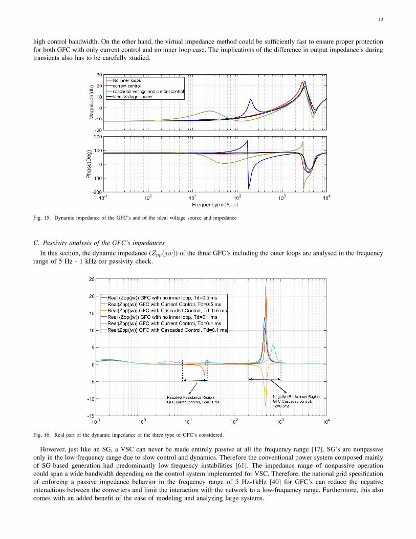
C. Passivity analysis of the GFC’s impedances
In this section, the dynamic impedance (Zpp(jw)) of the three GFC’s including the outer loops are analysed in the frequencyrange of 5 Hz - 1 kHz for passivity check.
Fig. 16. Real part of the dynamic impedance of the three type of GFC’s considered.
However, just like an SG, a VSC can never be made entirely passive at all the frequency range [17]. SG’s are nonpassiveonly in the low-frequency range due to slow control and dynamics. Therefore the conventional power system composed mainlyof SG-based generation had predominantly low-frequency instabilities [61]. The impedance range of nonpassive operationcould span a wide bandwidth depending on the control system implemented for VSC. Therefore, the national grid specificationof enforcing a passive impedance behavior in the frequency range of 5 Hz-1kHz [40] for GFC’s can reduce the negativeinteractions between the converters and limit the interaction with the network to a low-frequency range. Furthermore, this alsocomes with an added benefit of the ease of modeling and analyzing large systems.

13
The real part of the modified positive sequence impedance is shown in Fig. 16. It can be seen from both the figures that theGFC without any inner loop behaves as passive impedance in the frequency of interest as it does not have a nonnegative realpart. Whereas the (Zpp(jw) for both GFC with current control as well as the GFC with cascaded control has a negative realpart in the frequency range of 10-15 Hz and 300-600 Hz, respectively, for the designed control parameters. However, when thetime constant of the current control is increased to 1 ms for a 10 kHz switched converter, there is no negative resistance regionin the output impedance of the GFC. This implies that the presence of an inner loop in low switching frequency converters,as is the case with high power converters, could result in unstable oscillations. The result is nis similar to the results derivedfrom impedance-based passivity analysis conducted on PLL-based VSC. Ref. [22], [63] reported that the current control andfeed-forward filters, along with the PLL, also contribute to VSC’s nonpassive behavior. Therefore, merely eliminating the PLLalone is not enough to ensure the converter impedance behaves passively, as it is demonstrated in Fig. 16.
Although, refs. [23], [57], [66] discuss design techniques and controls for increasing the passivity behavior of VSC withLCL filter and current control. The techniques and controls have to be carefully considered before adapting to GFC. Similarly,ref [67] also discusses the challenges and methods in ensuring passivity until the Nyquist frequency range (0 − fs/2)forcascaded voltage-controlled converters. In conclusion to this section, it can be said that the requirement of GFC behaving asa voltage source behind an impedance in the frequency range of interest is satisfied for GFC without inner loops, whereas itis not straightforward for GFC’s with inner loop to ensure passivity. Furthermore, as the converter is rated for high power,the switching frequency reduces, thus aggravating the stability issues due to the nonpassive behavior of power converterimpedances.
D. Impact of inner loop on electromechanical mode
Fig. 17. Trajectory of swing mode of GFC with no inner loop and GFC with current control by simultaneously increasing transmission line impedance’s(ZTL1, ZTL2) from 0.01 to 0.5 pu
The future power system will be composed of a mix of SG and VSC, hence it is important to study the interaction betweenGFC and SG. For SG, the damping is realized through damper windings and is typically low, whereas the damping effect forGFC can be easily programmed and is constrained only by the size of the dc energy storage. Consequently, it is essential toensure that the inner loops do not adversely affect electromechanical mode. Such study should be conducted in a test systemconsisting of both SG and GFC. Most recent publications [46]–[48] that investigated GFC with cascaded inner loop did notconsider a SG in the studies. Therefore, the local electromechanical oscillation typically in the frequency of 0.7-2 Hz is notpresent in any of these studies. Thus the impact of inner loops on the electromechanical mode of SG has not been evaluated.Furthermore, ref. [47], [48] has no inertia programmed in control, hence an oscillatory mode arising due to virtual inertia isabsent.
In this section, a small-signal analysis is carried to evaluate the difference in impact on the electromechanical mode bythe three considered GFC’s. First, an eigenanalysis is conducted on the derived small-signal model, and the electromechanicalmodes are identified from the participation factors. Major participants of the swing modes are the SG’s rotor speed and activepower control loop of the GFC’s. In the case of SG, the swing mode moves towards RHP when the grid strength is reduced[61], and one would expect similar behavior with the GFC. However, unlike an SG where additional damping has to beprovided by indirect means such as power system stabilizers, the GFC can be damped using control paramaters.

14
Fig. 18. Trajectory of swing mode of GFC with cascaded inner loop with simultaneously increasing transmission line impedance’s (ZTL1, ZTL2) from 0.01to 0.5 pu for control designs specified in Table. III
The trajectory of swing mode of GFC with no inner loop and GFC with current control by simultaneously increasingtransmission line impedance’s (ZTL1, ZTL2) from 0.01 to 0.5 pu is shown in Fig. 17, the case is repeated for GFC switchingat 2 kHz and 10 kHz. Compared to GFC without inner loop GFC, the swing modes in GFC with current control are slightlymore sensitive to change in grid impedance. However, GFC with current control can provide slightly higher damping in lowgrid impedance scenarios, but the differences in the trajectory and position of the eigenvalues are not significantly differentfrom each other. It can also be seen that the change in the switching frequency hardly affects the swing modes in both theGFC with current control and GFC with no inner loop.
The electromechanical mode in both cases moves to the right as the grid impedance is increased; however, it is quite possibleto ensure sufficient damping even at very low grid strength. Compared to GFC without inner loop GFC, swing modes in thecase of GFC with current control are slightly more sensitive to change in grid impedances. However, GFC with current controlcan provide slightly higher damping in low grid impedance scenarios, but the differences in the trajectory and position of theeigenvalues are not significantly different from each other. It can also be seen that the change in PWM delay hardly affectsthe swing modes in both the GFC with current control and GFC with no inner loop. From these studies, it can be observedthat the presence of an current control alone in GFC with current control does not negatively impact the damping of theelectromechanical mode.
The swing modes of GFC with cascaded inner control by simultaneously increasing transmission line impedance’s (ZTL1, ZTL2)from 0.01 to 0.5 pu for all the three control design objective is shown in Fig. 18. The results of the Eigen trajectory designone and two shown in Table. III, which seems to be moving left initially as the transmission line impedances (ZTL1, ZTL2)are increased before shifting the trajectory back towards RHP.
On the other hand the eigenvalues consistently move towards RHP as the network impedance is increased when designparameters of the GFC are corresponding to design 3 in Table. III. This trajectory is similar to how electromechanical modewould move as in the case of the other two GFC’s or an SG. Furthermore, electromechanical eigenvalues with design 1 and2 are always underdamped compared to the electromechanical eigenvalue results with GFC with no inner loop and GFC withcurrent control inner loop at similar grid strength. On the other hand GFC with cascaded control provided equivalent dampingto the electromechanical mode as the GFC with no inner loop and GFC with current control inner loop with design threeparameters.
The Ref. [46]–[48], concludes that an increase in grid impedance is better for the stability of the GFC with cascaded voltagecontrol. Although the test system and outer loop parameters are different with Ref. [46]–[48], the eigen analysis presented inthis paper shows that such a conclusion is not unconditionally true and can depend on the system considered, control design,power rating, and structure of the cascaded voltage control.
VI. TIME DOMAIN SIMULATION STUDY
The focus on the time-domain analysis presented in this section is to verify the conclusions drawn in small-signal analysisand verify if the response from all the three GFC types is simillar to a voltage source. It is concluded in the small-signalanalysis that the GFC types with inner loops for MW level converter could be nonpassive in certain frequency ranges. It is alsoconcluded that the GFC with cascaded control could negatively impact the electromechanical damping when system strengthimproves. The time-domain simulation results presented validate this conclusion.

15
Fig. 19. Response for a infinite bus voltage dip to 0.5 p.u
Fig. 20. Response for a infinite bus angle jump of 10 degree
vl
Load
ipcc
L1 R1
Rf
Cf
ivsc
vvsc vpcc
SGvsg
ZTL1a
ZTL1b
ZT1
S1
ZTL2a
S2 ZTL2b
1 1 11 T TL a TL bZ Z Z Z 2 22 TL a TL bZ Z Z
Fig. 21. The test system to evaluate the implication of different impedance behaviour and robustness of the three GFCs against a network impedance change
A. Response of the GFC’s connected to an infinite bus
The grid forming capability of the GFC is first evaluated against an infinite voltage source, the responses of interest hereare active and reactive power output of the GFC’s against a step change in infinite bus voltage and step change in angle of theinfinite bus. The GFC POC bus is connected to the infinite bus through a 0.1 p.u reactance. The net steady state impedancebetween the infinite bus and the voltage source representing GFC will include the physical network impedance of 0.2 p.u andthe impedance of 0.15 p.u of GFC internal impedance. It has to be noted that the GFC internal impedance is emulated using

16
virtual impedance as in the case of GFC with inner loop, or adjusted with filter impedance to get total of 0.15 p.u for GFCwith no inner loops.
The output response of a voltage source behind an impedance against a grid event depends on the total impedance and themagnitude of the voltage, which in this case is similar for all the three converter in steady state. For instance, smaller theimpedance, larger the expected reactive power exchange during voltage dip. Similarly, smaller the impedance, larger the activepower exchange expected during voltage phase shift. Therefore, provided that the GFC’s have similar impedance, the responsesare also expected to be same. For a dip in infinite bus voltage to 0.5 p.u, the considered GFC’s have similar responses fromthe three GFC’s considered in steady-state as seen in Fig. 19. However, the GFC with a cascaded inner loop has a larger thanexpected spike immediately after the dip in voltage compared to the other two. Such spike can be attributed to the cascadedloop’s slow dynamics, resulting in an emulated impedance that is relatively slow and presents a varying impedance than aconstant impedance. The impact of this slow dynamics of the virtual impedance for cascaded control is also seen in responseto the phase jump of the infinite bus voltage, as seen in Fig.20. The slow varying impedance is an undesirable characteristic asit can trigger the current limit and presents a problem in dynamic power-sharing under parallel connection of voltage sources.
Fig. 22. Active and reactive power time domain response of the GFC with no inner loop under network impedance impedance Z1 increase from 0.15 pu to0.6 pu
Fig. 23. Active and reactive power time domain response of the GFC cascaded inner loop under network impedance impedance Z1 increase from 0.15 puto 0.6 pu
B. Case Study
A time domain Case study to evaluate the implication of different impedance behaviour and robustness of the three GFC’sagainst a network impedance change are conducted. The GFC with time delay corresponding to PWM frequency of 2 kHz is

17
Fig. 24. Active and reactive power time domain response of the GFC with current control inner loop under network impedance impedance Z1 increase from0.15 pu to 0.6 pu
chosen for the study. The time domain study is closely aligned with the small signal analysis presented in Section V. A testsystem as shown in Fig. 21 is implemented in MATLAB/SIMULINK. The impedance Z1 is the the net impedance betweenPCC bus and load bus, and Z2 is the net impedance between load and SG bus. For the first case, the three GFC’s are evaluatedagainst an increase in network impedance change event. During pre-network impedance change event, the switch S2 is off andS1 is on, ensuring both Z1 and Z2 to be 0.2 pu. Also, both the SG and the GFC’s are sharing 1 pu load equally between thethem. Switch S1 is opened at 5 seconds, increasing impedance between the PCC bus and the load bus (Z1) to 0.6 pu. Thetest case is repeated for systems with all the three GFC’s. As seen in Fig. 22, the GFC without inner loop behaves as voltagesource behind an impedance and settling to steady state as soon as the swing mode are damped out. The results align withthat of Section V, which predicted the GFC with no inner loop is passive and swing modes are also damped for all possiblenetwork impedance combinations.
Fig. 25. Active and reactive power time domain response of the GFC with cascaded control under network impedance impedance Z1 and Z2 decreased from0.2 pu to 0.1 pu
The investigating on swing modes and network impedance revealed that the high power GFC with cascaded control, switchingat low frequency could have underdamped or undamped electromechanical mode when the network impedances are reduced.Such a characteristics is unlike an SG or the other configuration of GFC’s and is unique to GFC with cascaded control. Thesimulations are conducted with GFC cascaded control with the three design shown in Table.III with the network impedanceimpedance Z1 and Z2 decreased from 0.2 pu to 0.1 pu at 15 seconds. The results are depicted in Fig. 25. It can be seenthat for design one with lower switching frequency the swing modes get undamped at 15 seconds, whereas, if the switchingfrequency was higher as in the case of design 2 and 3 the electromechanical mode is still stable.

18
Fig. 26. Response of the GFC’s for a 3L-G fault
Fig. 27. Response of the GFC’s for a 0.5 p.u load switching
The behaviour of the GFC for a 3-phase fault case is shown in Fig. 26, which demonstrates a fast fault current contributionfrom all the three cases, with cascaded inner loop GFC a larger current contribution in the beginning of the fault can be seendue to the slow dynamics of the virtual impedance. One of the main advantage of a synchronous machine, being a voltagesource is that it can contribute to load sharing instantly without relying on control or measurements. The results for a 0.5 p.uload turn on and off when the net impedance between PCC and load is 0.15 p.u is shown in Fig. 27 and 28. The response showsthat all the three GFC have voltage source characteristics as the load is shared instantly by the GFC’s. On closer examinationit can be seen that power shared at the load switching instant is slightly higher for cascaded inner loop GFC case due to slowdynamics of the virtual impedance.
VII. SUMMARY
A comprehensive study on the inner loop’s impact on the ability of GFC to behave as a voltage source behind an impedanceis presented in this paper. Three of the most popular GFC structures, (i) GFC with cascaded voltage control and currentcontrol, (ii) with inner current control only, (iii) with no inner loop, are compared in this paper. A small-signal model of aGFC connected to an SG system was derived to assess the dynamic impedances of the three GFC’a and study the impact ofinner loops on elctromechanical mode. Assessing the dynamic impedance of the three GFC’s derived from the small-signalshowed that it is challenging to ensure a passive impedance behavior in a broad frequency range for GFC with the inner loop.This is particularly true for high power GFC’s with low switching frequency because of the PWM delay. Because of this,unstable oscillations may arise for a system composed of GFC with inner loops under weak grid conditions.

19
Fig. 28. Response of the GFC’s for a 0.5 p.u load disconnection
TABLE IVSUMMARY OF GFC COMPARISONS
GFC with no innerloop
GFC with inner current control GFC with cascaded voltage control
Passivity Beyond outer con-trol Bandwidth
Passive Possibility for not passive at frequencydetermined by feed forward filter andcontrol bandwidth
Possibility for not Passive around reso-nant frequency range
Constraint on networkimpedance
No constraint Upper limit in non passive region Both upper and lower limit
Dynamic power-sharing Behaves like a voltagesource behind a fixed re-actance
Behaves like a voltage source behind afixed reactance
Behaves like a voltage source behinda time varying reactance due to slowacting virtual impedance
Virtual impedance currentlimiting
Possible Possible Limited application due to slow actingvirtual impedance
Electro-mechanical eigenvalue
No negative impact ondamping
No negative impact on damping Negative impact on damping, dependson control design
Also, the time domain studies performed in the paper showed that the GFC configuration with the inner current control andno inner loop could respond similar a voltage source under a strong grid scenario. Whereas, for the GFC with a cascadedinner loop, the impedance is found to be slow-acting and only effective in very low frequency range because of the loopdelays. This slow acting virtual impedance of the cascaded GFC results in higher than expected instantaneous active powerand reactive power for a grid event, which may trigger unexpected overcurrent protection as the semiconductor devices aresensitive to over current. Moreover, this slow-acting virtual impedance is seen as a slowly changing time-varying impedance inthe GFC’s terminal characteristics with cascaded control, causing problems in dynamic reactive power-sharing. Furthermore,the slow acting virtual impedance can also limits the application of virtual impedance based current limiting in GFC withcascaded controller.
Additionally, a study on the electromechanical oscillation mode of the SG was conducted with the three GFC configurations.It was found that the impact of PWM delays for GFC configuration with no inner loop or only inner current controller ismarginal.The damping of the electromechanical mode for GFC configuration with no inner loop or only inner current controlleris better than GFC with cascaded control at all network strength. The electromechanical oscillation mode for GFC with cascadedcontrol is sensitive to the inner loop. And unlike an SG or the other configurations of GFC, it is found that a high powerconverter with low switching can be unstable with low network impedance. And the electromechanical oscillation mode canmove towards a more stable region as the network impedance is increased. Consequently, GFC with cascaded control couldhave both an upper bound on the network impedance due to passivity-related high-frequency oscillations and a lower boundfor network impedance to ensure damping for electromechanical mode. Furthermore, this paper shows that weakening of theelectromechanical mode damping with an increase in grid strength is control design and converter-specific, and converse couldbe true for a different control design for converters with higher switching frequency. With an other control design objectiveand higher switching frequency, one can achieve similar damping for electromechanical mode with the GFC with cascadedcontrol as that of GFC with no inner loop.

20
VIII. DISCUSSION AND CONCLUSION
The study conducted in the paper is constrained to the inner loop’s impact on the ability of GFC to behave like a voltagesource behind an impedance for fundamental components of currents. The GFC is also expected to be a sink for harmonicsand unbalances [17]. Only GFC with no inner loop and programmed inertia can present a natural sink to harmonics, inter-harmonics, and unbalance within the hardware capability without making any changes to the control structures. The GFCwith inner loops would require additional control loops to sink for the harmonics and unbalance simillar to a grid followingconverter [68]. On the other hand, with additional parallel loops, the GFC with inner loops can respond selectively to theharmonics or unbalances, which could be beneficial for the system. In this case, the open question would be on standardizingthe harmonic contributions required from GFC’s.
From a modeling and simulation perspective, the GFC’s present several challenges, with the potential to instigate the adverseinteraction at higher frequencies; the practicability of limiting more extensive power system studies to RMS simulation will besignificantly challenged. One research direction would be on developing accurate RMS models for GFC. To sufficiently capturethe actual dynamics of the GFC using RMS models, constraints would need to place bandwidth and stability margin limitationson GFC controls. Additionally, the RMS model also needs to be validated against an EMT model of a more extensive powersystem network. A framework and test power systems for validating the RMS model of GFC’s is still missing in the literature.
The GFC synchronization and power control loop are the same. Therefore, unlike the conventional grid supporting converter,which directly controls the active and reactive current setpoints and the option to limit the active or reactive power withoutaffecting voltage-based synchronization, implementing the power or current limiters for GFC is challenging. The current andpower limit could be triggered during fault cases or from overload scenarios arising from changing system frequencies. Sincethe power control is also the synchronization control, there is a necessity for coordination between power control loops andcurrent limits. The challenge of current limiting is even higher for GFC with no inner loop. GFC current limit has beenimplemented using virtual impedance and freezing the power loop [7], by switching the grid forming control to PLL-basedgrid the following control [31], adaptively changing the doop parameters [69] and by employing voltage limitation for currentlimitations [70]. However, the focus of the studies has been limited to mostly on either the current limiting during a shortcircuit or overload. The current and power limit needs to be robust against both overload and fault cases and must also bedemonstrated in a more extensive system. Furthermore, the GFC impact on frequency stability considering active power, energy(state of charge), and current limitation also need to be studied. Additionally, the virtual impedance current limiting impactsthe system strength is also necessary to be studied.
ACKNOWLEDGMENT
The study is funded by Phoenix project, funded by Ofgem under Network Innovation Competition programme, ProjectDirection ref: SPT / Phoenix / 16 December 2016 (https://www.spenergynetworks.co.uk/pages/phoenix.aspx). Authors wouldalso like to acknowledge Thyge Knueppel from Siemens Gamesa, Jay Ramachandran National Grid, Qiteng Hong and CampbellBooth from University of Strathclyde for their valuable feedbacks during the paper preparations.

21
REFERENCES
[1] F. Milano, F. Dorfler, G. Hug, D. J. Hill, and G. Verbic, “Foundations and challenges of low-inertia systems,” in 2018 Power Systems ComputationConference (PSCC). IEEE, 2018, pp. 1–25.
[2] U. Markovic, O. Stanojev, E. Vrettos, P. Aristidou, and G. Hug, “Understanding stability of low-inertia systems,” 2019.[3] P. Tielens and D. Van Hertem, “The relevance of inertia in power systems,” Renewable and Sustainable Energy Reviews, vol. 55, pp. 999–1009, 2016.[4] H. Urdal, R. Ierna, J. Zhu, C. Ivanov, A. Dahresobh, and D. Rostom, “System strength considerations in a converter dominated power system,” IET
Renewable Power Generation, vol. 9, no. 1, pp. 10–17, 2014.[5] S. Homan, N. Mac Dowell, and S. Brown, “Grid frequency volatility in future low inertia scenarios: Challenges and mitigation options,” Applied Energy,
vol. 290, p. 116723, 2021.[6] K. S. Ratnam, K. Palanisamy, and G. Yang, “Future low-inertia power systems: Requirements, issues, and solutions-a review,” Renewable and Sustainable
Energy Reviews, vol. 124, p. 109773, 2020.[7] M. Yu, A. Dysko, A. Roscoe, C. Booth, R. Ierna, H. Urdal, and J. Zhu, “Effects of swing equation-based inertial response (SEBIR) control on penetration
limits of non-synchronous generation in the Gb power system,” IET Conf. Publ., vol. 2015, no. CP679, 2015.[8] N. Stojanovic, M. Grcar, S. Sen, and J. Ma, “Deliverable D1. 1 Report,” MIGRATE - Massive Integr. power Electron. devices, no. 691800, 2019.[9] E.-E. guidance document for national implementation for network codes on grid connection, “Fault current contribution from ppms & hvdc,” Draft of
Expert Group FFCI, Tech. Rep., 2017.[10] I. W. Group, “Technical requirements for fast frequency reserve provision in the nordic synchronous area external document,” ENTSO-E, Tech. Rep.,
2020.[11] National Grid Electricity System Operator, “The Grid Code (Uk),” no. 5, pp. 0–1014, 2020.[12] Nationalgrideso, “Operability strategy report 2021,” Nationalgrideso, Tech. Rep., 2021.[13] M. Rezkalla, A. Zecchino, S. Martinenas, A. M. Prostejovsky, and M. Marinelli, “Comparison between synthetic inertia and fast frequency containment
control based on single phase evs in a microgrid,” Applied Energy, vol. 210, pp. 764–775, 2018.[14] H. T. Nguyen, G. Yang, A. H. Nielsen et al., “Frequency stability enhancement for low inertia systems using synthetic inertia of wind power,” in 2017
IEEE Power & Energy Society General Meeting. IEEE, 2017, pp. 1–5.[15] R. Eriksson, N. Modig, and K. Elkington, “Synthetic inertia versus fast frequency response: a definition,” IET Renewable Power Generation, vol. 12,
no. 5, pp. 507–514, 2017.[16] S. C. Johnson, J. D. Rhodes, and M. E. Webber, “Understanding the impact of non-synchronous wind and solar generation on grid stability and identifying
mitigation pathways,” Applied Energy, vol. 262, p. 114492, 2020.[17] ENTSO-E, “High Penetration of Power Electronic Interfaced Power Sources and the Potential Contribution of Grid Forming Converters,” p. 32, 2019.[18] J. Liu, Y. Miura, and T. Ise, “Comparison of dynamic characteristics between virtual synchronous generator and droop control in inverter-based distributed
generators,” IEEE Transactions on Power Electronics, vol. 31, no. 5, pp. 3600–3611, 2015.[19] J. Jia, G. Yang, A. H. Nielsen, and P. Rønne-Hansen, “Impact of vsc control strategies and incorporation of synchronous condensers on distance protection
under unbalanced faults,” IEEE Transactions on Industrial Electronics, vol. 66, no. 2, pp. 1108–1118, 2018.[20] NERC, “Reliability guideline: Bps-connected inverterbased resource performance,” Atlanta, GA,, Tech. Rep., Sept 2018.[21] B. Wen, D. Boroyevich, R. Burgos, and P. Mattavelli, “Input impedance of voltage source converter with stationary frame linear current regulators and
phase-locked loop,” in 2013 IEEE Energy Conversion Congress and Exposition. IEEE, 2013, pp. 4207–4213.[22] B. Wen, D. Boroyevich, R. Burgos, P. Mattavelli, and Z. Shen, “Analysis of dq small-signal impedance of grid-tied inverters,” IEEE Transactions on
Power Electronics, vol. 31, no. 1, pp. 675–687, 2015.[23] L. Harnefors, M. Bongiorno, and S. Lundberg, “Input-admittance calculation and shaping for controlled voltage-source converters,” IEEE transactions
on industrial electronics, vol. 54, no. 6, pp. 3323–3334, 2007.[24] K. V. Kkuni, S. Ghosh, G. Yang, and C. Booth, “Modelling and passivity analysis of vsc output impedance under srf and alpha-beta control frames,” in
IECON 2019-45th Annual Conference of the IEEE Industrial Electronics Society, vol. 1. IEEE, 2019, pp. 1856–1861.[25] Phoenix System Security and Synchronous Condenser. [Online]. Available: https://www.spenergynetworks.co.uk/pages/phoenix.aspx[26] Synchronous Condensers Application in Low Inertia Systems (SCAPP). [Online]. Available: http://www.scapp.dk/home[27] M. Nuhic, K. V. Kkuni, and J. Ramachandran, “Comparative study of hybrid synchronous condenser incorporating battery energy storage system for
ancillary service provision,” in Proceedings of the 18th Wind Integration Workshop, Energynautics GmbH, 2020.[28] E. Marrazi, G. Yang, and P. Weinreich-Jensen, “Allocation of synchronous condensers for restoration of system short-circuit power,” Journal of Modern
Power Systems and Clean Energy, vol. 6, no. 1, pp. 17–26, 2018.[29] J. Jia, G. Yang, A. H. Nielsen, E. Muljadi, P. Weinreich-Jensen, and V. Gevorgian, “Synchronous condenser allocation for improving system short circuit
ratio,” in 2018 5th International Conference on Electric Power and Energy Conversion Systems (EPECS). IEEE, 2018, pp. 1–5.[30] Q.-C. Zhong and T. Hornik, “Synchronverters: grid-friendly inverters that mimic synchronous generators,” 2012.[31] L. Zhang, “Power system stability analysis using feedback control system modeling including hvdc transmission links,” Ph.D. dissertation, Royal Institute
of Technology, Stockholm,Sweden, 2010.[32] M. Chen, D. Zhou, and F. Blaabjerg, “Modelling, implementation, and assessment of virtual synchronous generator in power systems,” Journal of Modern
Power Systems and Clean Energy, vol. 8, no. 3, pp. 399–411, 2020.[33] R. H. Lasseter, Z. Chen, and D. Pattabiraman, “Grid-forming inverters: A critical asset for the power grid,” IEEE Journal of Emerging and Selected
Topics in Power Electronics, vol. 8, no. 2, pp. 925–935, 2019.[34] K. M. Cheema, “A comprehensive review of virtual synchronous generator,” International Journal of Electrical Power & Energy Systems, vol. 120, p.
106006, 2020.[35] R. Ierna, J. Zhu, A. J. Roscoe, M. Yu, A. Dysko, C. D. Booth, and H. Urdal, “Effects of vsm convertor control on penetration limits of non-synchronous
generation in the gb power system,” in 15th Wind Integration Workshop, 2016.[36] G. Denis, T. Prevost, M.-S. Debry, F. Xavier, X. Guillaud, and A. Menze, “The migrate project: the challenges of operating a transmission grid with
only inverter-based generation. a grid-forming control improvement with transient current-limiting control,” IET Renewable Power Generation, vol. 12,no. 5, pp. 523–529, 2018.
[37] ELectranet, “Escri-sa battery energy storage project operational report #3,” Tech. Rep., 2021.[38] A. Roscoe, P. Brogan, D. Elliott, T. Knueppel, I. Gutierrez, J. Perez Campion, and R. Da Silva, “Practical experience of operating a grid forming wind
park and its response to system events,” in Proceedings of the 18th Wind Integration Workshop, Energynautics GmbH, 2019.[39] A. Roscoe, T. Knueppel, R. Da Silva, P. Brogan, I. Gutierrez, D. Elliott, and J.-C. P. Campion, “Response of a grid forming wind farm to system events,
and the impact of external and internal damping,” IET Renewable Power Generation, 2020.[40] N. G. ESO, “Stability pathfinder oct 2019, draft grid code grid forming and request for information feedback,” Tech. Rep.[41] M. Paolone, T. Gaunt, X. Guillaud, M. Liserre, S. Meliopoulos, A. Monti, T. Van Cutsem, V. Vittal, and C. Vournas, “Fundamentals of power systems
modelling in the presence of converter-interfaced generation,” Electric Power Systems Research, vol. 189, p. 106811, 2020.[42] H. Xu, C. Yu, C. Liu, Q. Wang, and X. Zhang, “An improved virtual inertia algorithm of virtual synchronous generator,” Journal of Modern Power
Systems and Clean Energy, vol. 8, no. 2, pp. 377–386, 2019.[43] U. Tamrakar, D. Shrestha, M. Maharjan, B. P. Bhattarai, T. M. Hansen, and R. Tonkoski, “Virtual inertia: Current trends and future directions,” Applied
Sciences, vol. 7, no. 7, p. 654, 2017.

22
[44] H. A. Alsiraji and J. M. Guerrero, “A new hybrid virtual synchronous machine control structure combined with voltage source converters in islanded acmicrogrids,” Electric Power Systems Research, vol. 193, p. 106976, 2021.
[45] M. G. Taul, X. Wang, P. Davari, and F. Blaabjerg, “Current limiting control with enhanced dynamics of grid-forming converters during fault conditions,”IEEE Journal of Emerging and Selected Topics in Power Electronics, vol. 8, no. 2, pp. 1062–1073, 2019.
[46] Z. Qu, J. C.-H. Peng, H. Yang, and D. Srinivasan, “Modeling and analysis of inner controls effects on damping and synchronizing torque componentsin vsg-controlled converter,” IEEE Transactions on Energy Conversion, 2020.
[47] W. Du, Z. Chen, K. P. Schneider, R. H. Lasseter, S. P. Nandanoori, F. K. Tuffner, and S. Kundu, “A comparative study of two widely used grid-formingdroop controls on microgrid small-signal stability,” IEEE Journal of Emerging and Selected Topics in Power Electronics, vol. 8, no. 2, pp. 963–975,2019.
[48] C. Li, J. Liang, L. M. Cipcigan, W. Ming, F. Colas, and X. Guillaud, “Dq impedance stability analysis for the power-controlled grid-connected inverter,”IEEE Transactions on Energy Conversion, vol. 35, no. 4, pp. 1762–1771, 2020.
[49] R. Ierna, A. Dysko, and C. Booth, “Enhanced Virtual Synchronous Machine (VSM) Control Algorithm for Hybrid Grid Forming Converters,” 18th WindIntegr. Work., 2019.
[50] V. Natarajan and G. Weiss, “Synchronverters with better stability due to virtual inductors, virtual capacitors, and anti-windup,” IEEE Transactions onIndustrial Electronics, vol. 64, no. 7, pp. 5994–6004, 2017.
[51] Q.-C. Zhong and G. Weiss, “Synchronverters: Inverters that mimic synchronous generators,” IEEE transactions on industrial electronics, vol. 58, no. 4,pp. 1259–1267, 2010.
[52] P. Rodriguez, I. Candela, and A. Luna, “Control of pv generation systems using the synchronous power controller,” in 2013 IEEE Energy ConversionCongress and Exposition. IEEE, 2013, pp. 993–998.
[53] W. Zhang, D. Remon, and P. Rodriguez, “Frequency support characteristics of grid-interactive power converters based on the synchronous powercontroller,” IET Renewable Power Generation, vol. 11, no. 4, pp. 470–479, 2017.
[54] D. Remon, W. Zhang, A. Luna, I. Candela, and P. Rodriguez, “Grid synchronization of renewable generation systems using synchronous power controllers,”in 2017 IEEE 6th International Conference on Renewable Energy Research and Applications (ICRERA). IEEE, 2017, pp. 169–174.
[55] X. Li, G. Chen, and M. S. Ali, “Improved virtual synchronous generator with transient damping link and its seamless transfer control for cascadedh-bridge multilevel converter-based energy storage system,” IET Electric Power Applications, vol. 13, no. 10, pp. 1535–1543, 2019.
[56] T. Prevost and G. Denis, “WP3 - Control and Operation of a Grid with 100 % Converter-Based Devices Deliverable 3 . 6: Requirement guidelines foroperating a grid with 100% power electronic devices.” MIGRATE - Massive Integr. power Electron. devices, no. 2019, 2019.
[57] H. Wu and X. Wang, “Passivity-based dual-loop vector voltage and current control for grid-forming vscs,” IEEE Transactions on Power Electronics,2020.
[58] T. Qoria, F. Gruson, F. Colas, X. Kestelyn, and X. Guillaud, “Current limiting algorithms and transient stability analysis of grid-forming vscs,” ElectricPower Systems Research, vol. 189, p. 106726, 2020.
[59] A. D. Paquette and D. M. Divan, “Virtual impedance current limiting for inverters in microgrids with synchronous generators,” IEEE Transactions onIndustry Applications, vol. 51, no. 2, pp. 1630–1638, 2014.
[60] C. Collados-Rodriguez, M. Cheah-Mane, E. Prieto-Araujo, and O. Gomis-Bellmunt, “Stability analysis of systems with high vsc penetration: Where isthe limit?” IEEE Transactions on Power Delivery, 2019.
[61] P. Kundur, Power System Stability and Control. McGraw-Hill Education,, 22 Jan 1994.[62] D. Sun, H. Liu, S. Gao, L. Wu, P. Song, and X. Wang, “Comparison of different virtual inertia control methods for inverter-based generators,” Journal
of Modern Power Systems and Clean Energy, vol. 8, no. 4, pp. 768–777, 2020.[63] L. Harnefors, X. Wang, A. G. Yepes, and F. Blaabjerg, “Passivity-based stability assessment of grid-connected vscsan overview,” IEEE Journal of
emerging and selected topics in Power Electronics, vol. 4, no. 1, pp. 116–125, 2015.[64] T. Suntio, T. Messo, and J. Puukko, Power electronic converters: dynamics and control in conventional and renewable energy applications. John Wiley
& Sons, 2017.[65] A. Rygg, M. Molinas, C. Zhang, and X. Cai, “A modified sequence-domain impedance definition and its equivalence to the dq-domain impedance
definition for the stability analysis of ac power electronic systems,” IEEE Journal of Emerging and Selected Topics in Power Electronics, vol. 4, no. 4,pp. 1383–1396, 2016.
[66] A. J. Agbemuko, J. L. Dominguez-Garcia, O. Gomis-Bellmunt, and L. Harnefors, “Passivity-based analysis and performance enhancement of a vectorcontrolled vsc connected to a weak ac grid,” IEEE Transactions on Power Delivery, 2020.
[67] Y. Liao, X. Wang, and F. Blaabjerg, “Passivity-based analysis and design of linear voltage controllers for voltage-source converters,” IEEE Open Journalof the Industrial Electronics Society, vol. 1, pp. 114–126, 2020.
[68] M. L. Remus Teodorescu and P. Rodrıguez, “Grid Converters for Photovoltaic and Photovoltaic and,” pp. 51–56, 2011.[69] D. Groß and F. Dorfler, “Projected grid-forming control for current-limiting of power converters,” in 2019 57th Annual Allerton Conference on
Communication, Control, and Computing (Allerton). IEEE, 2019, pp. 326–333.[70] J. Chen, F. Prystupczuk, and T. O’Donnell, “Use of voltage limits for current limitations in grid-forming converters,” CSEE Journal of Power and Energy
Systems, vol. 6, no. 2, pp. 259–269, 2020.