1 database systems november 12/14, 2007 lecture #7
TRANSCRIPT

1
Database Systems
November 12/14, 2007Lecture #7

2
Announcement
• Assignment #3 is due on Monday (11/12) outside TA’s office in 336/338
• Assignment #4 will be out later this week.• How was the midterm exam?

3
Structure of DBMS
• Disk Space Manager– Manage space (pages) on
disk.• Buffer Manager
– Manage traffic between disk and main memory. (bring in pages from disk to main memory).
• File and Access Methods– Organize records into pages
and files.
Query Optimizationand Execution
Relational Operators
Files and Access Methods
Buffer Manager
Disk Space Manager
Applications
Queries

4
Storing Data: Disks and Files
Chapter 9
5
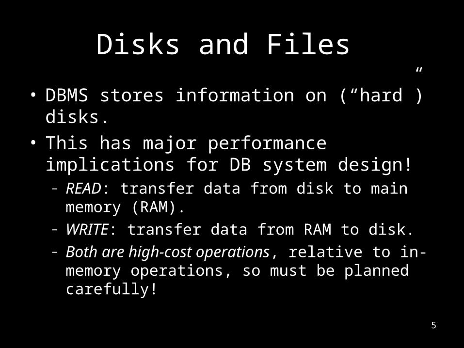
Disks and Files
• DBMS stores information on (“hard”) disks.• This has major performance implications for DB
system design!– READ: transfer data from disk to main memory (RAM).– WRITE: transfer data from RAM to disk.– Both are high-cost operations, relative to in-memory
operations, so must be planned carefully!

6
Why Not Store Everything in Main Memory?
• Costs too much. – $100 for 1G of SDRAM– $100 for 250 GB of HD (cost x250) – $40 for 50 GB of tapes. (cost same as HD) -> “Is Tape for
backup dead?”• Main memory is volatile.
– We want data to be saved between runs. • Typical storage hierarchy:
– Main memory (RAM) for currently used data.– Disk for the main database (secondary storage).– Tapes for archiving older versions of the data (backup
storage) or just disk-to-disk backup.

7
Disks• Secondary storage device of choice.
– Main advantage over tapes: random access vs. sequential.• Tapes are for data backup, not for operational data.
– Access the last byte in a tape requires winding through the entire tape.
• Data is stored and retrieved in units called disk blocks or pages.
• Unlike RAM, time to retrieve a disk page varies depending upon location on disk.
– Therefore, relative placement of pages on disk has major impact on DBMS performance!

8
Components of a Disk • The platters spin.• The arm assembly is mov
ed in or out to position a head on a desired track. Tracks under heads make a cylinder.
• Only one head reads/writes at any one time.
• Block size is a multiple of sector size (which is fixed).
Platters
Spindle
Disk head
Arm movement
Arm assembly
Tracks
Sector

9
10
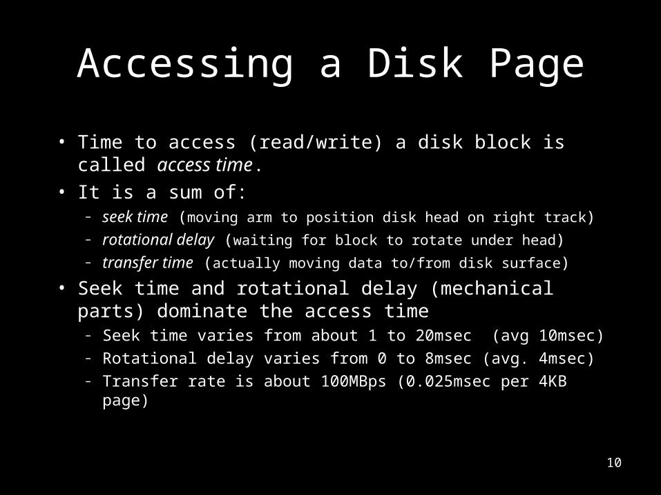
Accessing a Disk Page
• Time to access (read/write) a disk block is called access time.
• It is a sum of:– seek time (moving arm to position disk head on right track)– rotational delay (waiting for block to rotate under head)– transfer time (actually moving data to/from disk surface)
• Seek time and rotational delay (mechanical parts) dominate the access time
– Seek time varies from about 1 to 20msec (avg 10msec)– Rotational delay varies from 0 to 8msec (avg. 4msec)– Transfer rate is about 100MBps (0.025msec per 4KB page)

11

12
How to reduce I/O cost?
• access time = seek time + rotational latency + transfer time
• How to lower I/O cost?– Reduce seek/rotation delays!
• How to reduce seek/rotational delays for a large I/O requests of many pages?– If two pages of records are accessed together frequently, put
them close together on disk.

13
Arranging Pages on Disk
• Next block concept (measure the closeness of blocks)– (1) blocks on same track (no movement of arm), followed by– (2) blocks on same cylinder (switch head, but almost no
movement of arm), followed by– (3) blocks on adjacent cylinder (little movement of arm)
• Blocks in a file should be arranged sequentially on disk (by `next’), to minimize seek and rotational delay.
• For a sequential scan, pre-fetching several pages at a time is a big win!

14
Platters
Spindle
Disk head
Arm movement
Arm assembly
Tracks
Sector
1
2
3
Next Block Concept

15
RAID• RAID = Redundant Arrays of Independent (Inexpensive) Disks
– Disk Array: Arrangement of several disks that gives abstraction of a single, large disk.
• Goals: Increase performance and reliability.– Say you have D disks & each I/O request wants D blocks
• How to improve the performance (data transfer rate)?– Say you have D disks & D number of I/O request each wanting one
block• How to improve the performance (request service rate)?
– Say you have D disks and at most one disk can fail at any time• How to improve reliability (in case of disk failure)?

16
Two main techniques in RAID• Data striping improves performance.
– Data (e.g., in the same time file) is partitioned across multiple HDs; size of a partition is called the striping unit.
– Performance gain is from reading/writing multiple HDs at the same time.
• Redundancy improves reliability. – Data striping lowers reliability: More disks → more failures.– Store redundant information on different disks. When a disk fails, you
can reconstruct data from other disks.

17
RAID Levels• Level 0: No redundancy (only data striping)• Level 1: Mirrored (two identical copies)• Level 0+1: Striping and Mirroring• (Level 2: Error-Correcting Code)• Level 3: Bit-Interleaved Parity• Level 4: Block-Interleaved Parity• Level 5: Block-Interleaved Distributed Parity• (Level 6: Error-Correcting Code)• More Levels (01-10, 03/30, …)

18
RAID Level 0• Strip data across all drives (minimum 2 drives)• Sequential blocks of data (in the same file) are written across
multiple disks in stripes.• Two performance criterions:
– Data transfer rate: net transfer rate for a single (large) file– Request service rate: rate at which multiple requests (from different
files) can be serviced

19
RAID Level 0• Improve data transfer rate:
– Read 10 blocks (1~10) takes only 2-block access time (worse of 5 disks).– Theoretical speedup over single disk = N (number of disks)
• Improve request service rate:– File 1 occupies blocks 1 and file 2 occupies block 2. Service two
requests (two files) at the same time.– Given N disks, theoretical speedup over single disk = N.

20
RAID Level 0• Poor reliability:
– Mean Time To Failure (MTTF) of one disk = 50K hours (5.7 years).– MTTF of a disk array of 100 disks is 50K/100 = 500 hours (21 days)! – MTTF decreases linearly with the number of disks.
• Space redundancy overhead? – No overhead

21
Mirrored (RAID Level 1)• Redundancy by duplicating data on different disks:
– Mirror means copy each file to both disks– Simple but expensive.
• Fault-tolerant to a single disk failure– Recovery by copying data from the other disk to new disk.– The other copy can continue to service requests (availability) during
recovery.

22
Mirrored (RAID Level 1)• Performance is not the objective, but reliability.
– Mirroring frequently used when availability is more important than storage efficiency.
• Data transfer rate:– Write performance may be slower than single disk, why?
• Worse of 2 disks– Read performance can be faster than single disk, why?
• Consider reading block 1 from disk 0 and block 2 from disk 1 at the same time.
– Compare read performance to RAID Level 0?
• Better, but why? 3579
46810

23
Mirrored (RAID Level 1)
• Data reliability:– Assume Mean-Time-To-Repair (MTTR) is 1 hour.
• Shorter with Hotswap HDs.– MTTF of Mirrored 2-disks = 1 / (probability that 2 disks will fail within t
he same hour) = MTTR2/2 = (50K) 2/2 hours = many many years.• Space redundancy overhead:
– 50% overhead

24
Striping and Mirrors (RAID 0+1)
Disk 5 Disk 6 Disk 7 Disk 8 Disk 9

25
Bit-Interleaved Parity (RAID Level 3)
• Fine-grained striping at the bit level• One parity disk:
– Parity bit value = XOR across all data bit values • If one disk fails, recover the lost data:
– XOR across all good data bit values and parity bit value
0?
10
?1
00

26
Bit-Interleaved Parity (RAID Level 3)
• Performance:– Transfer rate speedup?
• x32 of single disk– Request service rate
improvement?• Same as single disk (do
one request at a time)
• Reliability:– Can tolerate 1 disk
failure.• Space overhead:
– One parity disk (1/33 overhead)

27
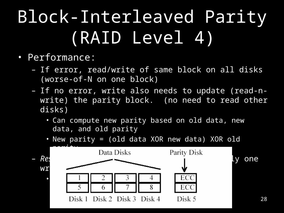
Block-Interleaved Parity (RAID Level 4)
• Coarse-grained striping at the block level– Otherwise, it is similar to RAID 3
• If one disk fails, recovery the lost block:– Read same block of all disks (including parity disk) to
reconstruct the lost block.
28
Block-Interleaved Parity (RAID Level 4)
• Performance:– If error, read/write of same block on all disks (worse-of-N on one
block)– If no error, write also needs to update (read-n-write) the parity block.
(no need to read other disks)• Can compute new parity based on old data, new data, and old parity• New parity = (old data XOR new data) XOR old parity
– Result in bottleneck on the parity disk! (can do only one write at a time)
• How to remove this bottleneck?

29
Block-Interleaved Parity (RAID Level 4)
• Reliability:– Can tolerate 1 disk failure.
• Space redundancy overhead:– 1 parity disk

30
Block-Interleaved Distributed-Parity (RAID Level 5)
• Remove the parity disk bottleneck in RAID L4 by distributing the parity uniformly over all of the disks. – No single parity disk as bottleneck; otherwise, it is the same as RAID 4.
• Performance improvement in write.– You can write to multiple disks (in 2-disk pairs) in parallel.
• Reliability & space redundancy are the same as RAID L4.

31
Structure of DBMS
• Disk Space Manager– manage space (pages) on
disk.• Buffer Manager
– manage traffic between disk and main memory. (bring in pages from disk to main memory).
• File and Access Methods– Organize records into pages
and files.
Query Optimizationand Execution
Relational Operators
Files and Access Methods
Buffer Manager
Disk Space Manager
Applications
Queries

32
Disk Space Manager
• Lowest layer of DBMS software manages space on disk.• Higher levels call upon this layer to:
– allocate/de-allocate a page– read/write a page
• Request for a sequence of pages should be satisfied by allocating the pages sequentially on disk! – Support the “Next” block concept (reduce I/O cost when multiple
sequential pages are requested at the same time).– Higher levels (buffer manager) don’t need to know how this is done,
or how free space is managed.
33
More on Disk Space Manager
• Keep track of free (used) blocks:– List of free blocks + the pointer to the first free block– Bitmap with one bit for each disk block. Bit=1 (used), bit=0
(free)– Bitmap approach can be used to identify contiguous areas
on disk.

34
Buffer Manager
• Typically, DBMS has more data than main memory.• Bring Data into main memory for DBMS to operate on it!• Table of <frame#, pageid> pairs is maintained.
DB
MAIN MEMORY
DISK
disk page
free frame
Page Requests from Higher Levels
BUFFER POOL
choice of frame dictatedby replacement policy

35
When a Page is Requested ...• If the requested page is not in pool (and no free
frame):– Choose an occupied frame for replacement
• Page replacement policy (minimize page miss rate)– If the replaced frame is dirty, write it to disk– Read requested page into chosen frame– Pin the page and return its address.
• For each frame, you maintain– Pin_count: number of outstanding requests– Dirty: modified and need to written back to disk
• If requests can be predicted (e.g., sequential scans) ..– pages can be pre-fetched several pages at a time.

36
More on Buffer Manager
• Requestor of page must unpin it (no longer need it), and indicate whether the page has been modified:
– dirty bit is used for this.• Page in pool may be requested many times,
– a pin count is used. A page is a candidate for replacement iff pin count = 0.

37
Buffer Replacement Policy• Frame is chosen for replacement by a replacement policy:
– FIFO, MRU, Random, etc. Which policy is considered as the best?• Least-recently-used (LRU): have LRU queue of frames with pin_count = 0
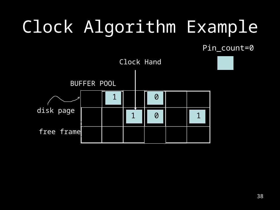
• What is the overhead of implementing LRU?• Clock (approximate LRU with less overhead)
– Use an additional reference_bit per page; set to 1 when the frame is accessed
– Clock hand moving from frame 0 to frame n.– Reset reference_bit of recently accessed frames.– Replace frame(s) with reference_bit = 0 & pin_count = 0.
• Policy can have big impact on # of I/O’s; depends on the access pattern.
38
Clock Algorithm Example
disk page
free frame
BUFFER POOL
Pin_count=0
1
1 10
0
Clock Hand
39
LRU may not be good: Sequential Flooding
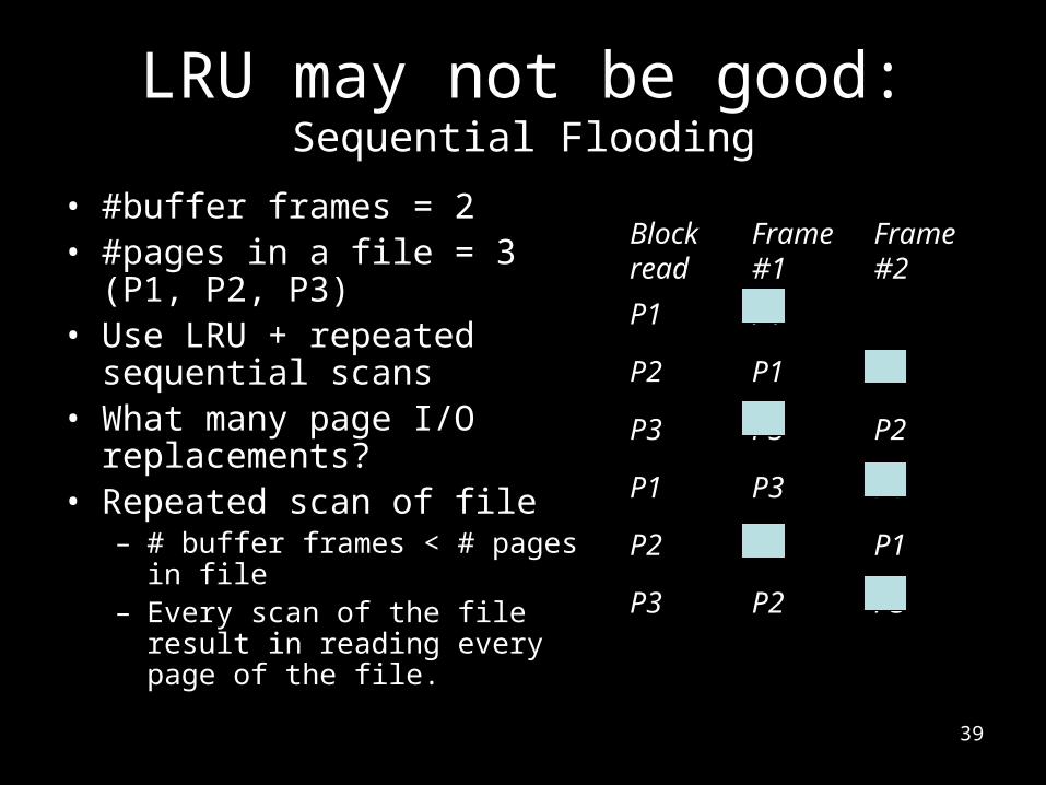
• #buffer frames = 2• #pages in a file = 3 (P1, P2, P3)• Use LRU + repeated sequential
scans• What many page I/O
replacements?• Repeated scan of file
– # buffer frames < # pages in file – Every scan of the file result in
reading every page of the file.
Block read
Frame #1
Frame #2
P1 P1
P2 P1 P2
P3 P3 P2
P1 P3 P1
P2 P2 P1
P3 P2 P3

40
DBMS vs. OS File System• OS also does disk space & buffer mgmt.• Why not let OS manage these tasks?
– Better predict the page reference patterns & pre-fetch pages.
• Adjust replacement policy, and pre-fetch pages based on access patterns in typical DB operations.
– Pin a page in memory and force a page to disk.• Differences in OS support: portability issues
– Maintain a virtual file that spans multiple disks.

41
Files of Records• Higher levels of DBMS operate on records, and files of r
ecords.• FILE: A collection of pages, each containing a collection
of records. Must support:– Insert/delete/modify record(s)– Read a particular record (specified using record id)– Scan all records (possibly with some conditions on the recor
ds to be retrieved)• To support record level operations, we must keep trac
k of:– Fields in a record: Record format– Records on a page: Page format– Pages in a file: File format

42
L1 L2 L3 L4
F1 F2 F3 F4
Record Formats (how to organize fields in a record): Fixed Length
• Information about field types and offset same for all records in a file; stored in system catalogs.
• Finding i-th field requires adding offsets to base address.
Base address (B) Address = B+L1+L2

43
Fields Delimited by Special Symbols
Record Formats: Variable Length• Two alternative formats (# fields is fixed):
Second alternative offers direct access to the i-th field, efficient storage of nulls (special don’t know value); small directory overhead.
4 $ $ $ $
FieldCount
F1 F2 F3 F4
F1 F2 F3 F4
Array of Field Offsets

44
Page Formats (How to store records in a page): Fixed Length Records
• Record id = <page id, slot #>. • They differ on how deletion (which creates a hole) is handled. • In first alternative, shift remaining records to fill hole => changes rid;
may not be acceptable given external reference.
Slot 1Slot 2
Slot N
. . . . . .
N M10. . .
M ... 3 2 1
PACKED UNPACKED, BITMAP
Slot 1Slot 2
Slot N
FreeSpace
Slot M
11
number of records
numberof slots
45
Page Formats: Variable Length Records
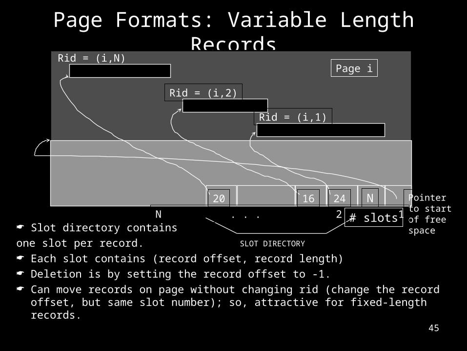
Slot directory contains one slot per record. Each slot contains (record offset, record length) Deletion is by setting the record offset to -1. Can move records on page without changing rid (change the record offset, but
same slot number); so, attractive for fixed-length records.
Page iRid = (i,N)
Rid = (i,2)
Rid = (i,1)
Pointerto startof freespace
SLOT DIRECTORY
N . . . 2 1
20 16 24 N
# slots

46
Unordered (Heap) Files
• Simplest file structure contains records in no particular order.
• As file grows and shrinks, disk pages are allocated and de-allocated.
• How would you implement a heap file (data structure)?– Double-Linked lists– Page directory
47
Heap File (Doubly Linked Lists)
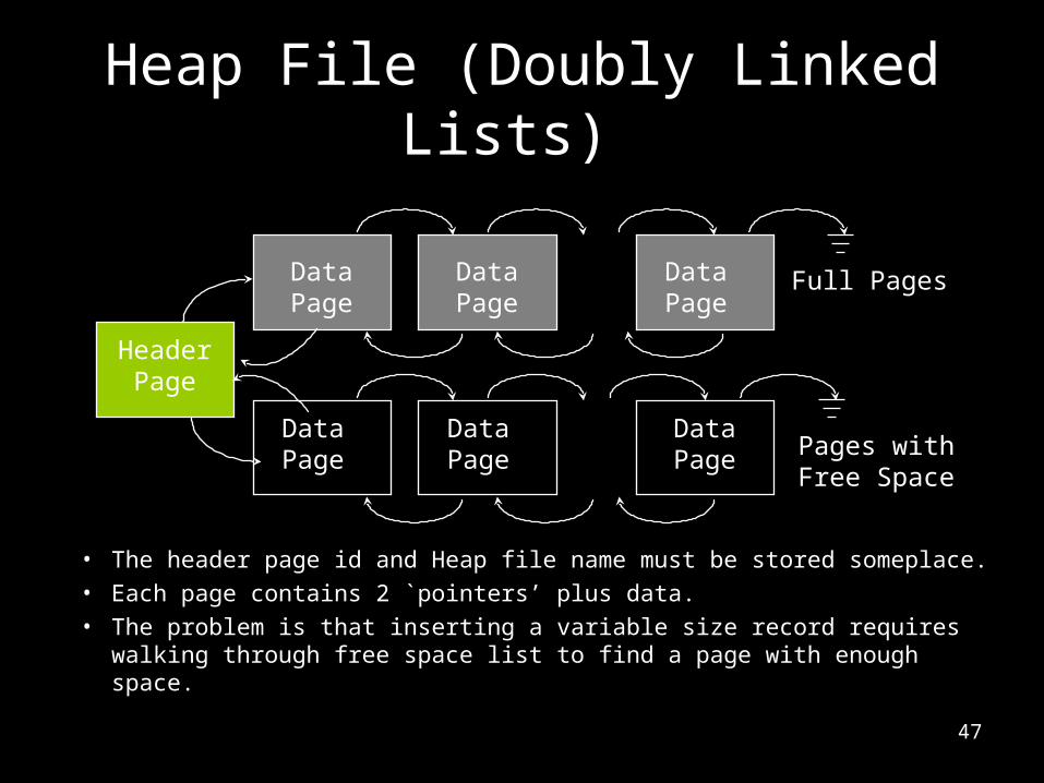
• The header page id and Heap file name must be stored someplace.• Each page contains 2 `pointers’ plus data.• The problem is that inserting a variable size record requires walking
through free space list to find a page with enough space.
HeaderPage
DataPage
DataPage
DataPage
DataPage
DataPage
DataPage Pages with
Free Space
Full Pages

48
Heap File (Page Directory)
• The directory is a collection of pages.– Each directory page contains multiple directory entries – one per
data page.– The directory entry contains <page id, free bytes on the page>– Eliminate the problem in the double-linked list approach.
DataPage 1
DataPage 2
DataPage N
HeaderPage
DIRECTORY