1 descriptions of function - eprismartgrid.epri.com/usecases/system level use case vmg ver5.pdf ·...
TRANSCRIPT

System Level Use Case VMG ver5.doc 1 11/29/2011
NNEEDDOO SSyysstteemm UUssee CCaassee ##KK11
EEnneerrggyy mmaannaaggeemmeenntt bbyy ccoonnffiigguurriinngg aa VViirrttuuaall MMiiccrrooggrriidd uussiinngg ppuubblliicc ccoommmmuunniiccaattiioonnss wwhheerree ppoowweerr iiss ssuupppplliieedd ttoo eenndd--uusseerrss wwhhiillee aacchhiieevviinngg ssiimmuullttaanneeoouuss bbaallaanncciinngg ooff ssuuppppllyy aanndd ddeemmaanndd
((NNEEDDOO KKEEEEPP PPrroojjeecctt))
VVeerrssiioonn 55..00 1188 NNoovv,, 22001111
1 Descriptions of Function
1.1 Function Name Energy management by configuring a Virtual Microgrid using public communications where power is supplied to end-users while achieving simultaneous balancing of supply and demand.
1.2 Function ID System Level Use Case K1
1.3 Brief Description This use case describes a “Virtual Microgrid (VMG)” that supplies power to end-users while achieving simultaneous balancing of supply and demand. “VMG” is a concept for specific distributed energy resources and power receiving facility to balance the total supply and demand in each time period (simultaneous balancing). Through construction of a VMG that includes renewable energy such as wind, PV and biomass, the use of these renewables can be maximized and the negative effects of output fluctuations on the commercial grid can be minimized.
In constructing a VMG, there may be cases where generation and loads are dispersed and located at great distances from each other. To achieve simultaneous balancing under such cases, it is desirable that the data entered into the system managing the simultaneous balancing (EMS) is time-stamped at the point of measurement. Also, it is possible to construct a cost-competitive VMG by employing existing public communications such as internet, thus avoiding building costly dedicated lines.

System Level Use Case VMG ver5.doc 2 11/29/2011
Technologies such as GPS can be used to generate measurement data with time stamps. Using public communications may present problems from the viewpoint of cyber security; however, these can be met by utilizing such technology as VPN (Virtual Private Network). In Japan, the concept of VMG was implemented by NEDO (New Energy and Technology Development Organization) in a demonstration project called “KEEP (Kyoto Eco Energy Project)” in Kyoto prefecture. The findings and knowledge obtained from this project form the basis for this use case. In KEEP, a Virtual Private Network (“VPN”) was created by using public telecommunications (standard ADSL, ISDN connections to the public Internet).
Substation Substation
Food disposal
biogas production
Simultaneous management center
battery energy storage
Fuel cell Gas engine
Bio-gas generator
Wind power Training institute
Solar power
Farming Park Complex housing
Measurement Data(generating, demands)
Remote measurement devices Internet VPN
Remote monitoringHospital City Branch
Office wastewater treatment facility
Solar power
Complex housing
Remote measurement devices
Remote measurement devices
Operation at Half 125kW
Reduce an natural energy fluctuation
Quantity Control
5sets
Total 400kW
Fig.1. NEDO KEEP Project

System Level Use Case VMG ver5.doc 3 11/29/2011
1.4 Narrative Because of intermittent output, generation from renewable energy sources (wind and photovoltaic) can have negative impacts on the operation of commercial grids. A VMG alone does not stabilize intermittent generation. But, in combination with other energy sources, it can provide a stable power supply to a specific area.
In order to achieve simultaneous power balancing between specific distributed generating equipment and power receiving equipment in a VMG, hourly time-stamped output data from each generating unit is collected at 10-sec. intervals via a VPN over public telecommunication lines and delivered to a communication server, where supply/demand imbalance is calculated. The resulting calculation is entered into the control system which implements simultaneous balancing (simultaneous balancing server and EMS) with minimum transmission delay (less than 10 sec.). At the EMS, on the other hand, the planned value for the operation of controllable generators is calculated. From this planned value and the calculation result at the communication server, the final output reference for the controllable generator (generation by biogas is assumed in this context) is calculated by the EMS, and the command is sent to the controllable generator. These functions of a VMG are described below in two stages.
◆Stage 1: Development of generation and power purchase plan based on demand and generation forecasts
Based on demand and generation forecasts, scheduling for controllable generators is developed by EMS. This stage is divided broadly into three steps, “long-term forecast,” “short-term forecast” and “scheduling.”
In the “long-term forecast” step, a rough forecast of load demand and generation for a week (48 times/day x 7 days) at 30-min. intervals is made based on the “weekly weather forecast” provided by a weather forecast service and historical demand data in the VMG.
In the “short-term forecast” step, a more accurate forecast than the long-term forecast is made for demand and intermittent generation output based on the “today and tomorrow’s weather forecast” provided by a weather forecast service and historical demand data in the VMG.
In the “scheduling” step, scheduling of controllable generators is conducted every half hour based on the results described above.

System Level Use Case VMG ver5.doc 4 11/29/2011
EMS
Weather forecast SP’s
server
1.2A: Weekly weather forecast1.5A: Weather forecast for the day and the next day
1.2B: Past demand patterns1.5B: Past demand patterns
1.3: Long-term demand forecast value1.6: Short-term demand forecast value
Short-term intermittent generation output forecast value1.7: Generation scheduling
1.1: Long-term forecast execution command1.4: Short-term forecast execution command
Fig.2. Diagram of Stage 1
◆Stage 2: Supply/demand control to achieve simultaneous balancing
The EMS controls supply of controllable generators to achieve simultaneous balancing based on the generation scheduling developed in Stage 1 and the real time measurement data obtained at the communication server. This stage is classified broadly into two steps, “real time measurement” and “real time reference value.”
- Real time measurement: The communication server collects actual result data at 10-sec. intervals that are obtained from RTUs installed in end-customers’ and/or generation facilities. These measurements are the data with time stamp of the sampling time. After sorting the obtained measurement data by time, the communication server calculates the imbalance between demand and supply within the VMG for each time.

System Level Use Case VMG ver5.doc 5 11/29/2011
- Generation of real time reference value: The EMS generates reference value for the operation of controllable generators based on generation scheduling developed in Stage 1 and the result of real time measurement, and transmits the command value to the controllable generator.
EMS
End-user RTU
2.1A: Power consumption of load
Communication server
Intermittent Renewables
RTU
Controllable generator’s
RTU
2.1B: Generation power ofintermittent renewables
2.1C: Generation power of controllable generators
2.2: Power consumption of load, generationPower of intermittent renewablesGeneration power of controllable generators
2.3: Supply-demand imbalance
2.4: Supply-demand imbalance
2.5: Output reference
Controllable generator’s controller
2.6: Output reference
Fig.3. Diagram of Stage 2

System Level Use Case VMG ver5.doc 6 11/29/2011
1.5 Actor (Stakeholder) Roles
Grouping (Community) Group Description
Actor Name Actor Type (person, organization, device, system, or subsystem)
Actor Description
EMS (simultaneous balancing)
System EMS, as the “heart” of the VMG, provides controllable generator’s output reference to develop generation scheduling and achieve balance of supply and demand in the VMG.
Communication server
System Communication server collects various measurement data from customer’s power receiving facilities and organizes the data for each hour to calculate imbalances of supply and demand within the VMG. The calculated supply and demand imbalance is sent to the EMS.
End-user RTU Device End-user’s RTU measures real time consumption data of customer’s power receiving facilities. The RTU’s clock is synchronized with other RTUs’ clocks by GPS.
Controllable generator RTU
Device This is the RTU that measures real time generation output of controllable generators. The RTU’s clock is synchronized with other RTUs’ clocks by GPS.
Controller for controllable generator
System This controller for controllable generator receives output reference from EMS to control controllable generators.
Intermittent Renewables (PV, WT, etc.) RTU
Device This is the RTU that measures real time generation output of renewables whose output cannot be adjusted (wind, PV, etc.).
Weather forecast SP server
System Weather forecast information, which is indispensable for developing generation scheduling, is provided by a weather forecast service provider.

System Level Use Case VMG ver5.doc 7 11/29/2011
1.6 Information exchanged
Information Object Name Information Object Description
Long-term forecast execution command
Long-term forecast of the day begins at 23:00 the previous day, following an issuance of the long-term forecast execution command at 23:00.
Short-term forecast execution command
Short-term forecast of the day begins at 23:30 the previous day, following an issuance of the short-term forecast execution command at 23:30.
Weekly weather forecast Highest and lowest temperatures for each day of the week ahead.
Weather forecast for the day and the next day
Forecast temperature for each period of time (e.g. 30 min.) for 24 hours.
Past demand pattern Database of past demand data.
Long-term demand forecast value Long-term demand forecast value is a rough demand forecast for a week, prepared based on weekly weather forecast data and past demand pattern.
Short-term demand forecast value Short-term demand forecast value, which is based on weather forecast for the day and the next day, is designed to be more detailed than the long-term demand forecast.
Short-term intermittent generation forecast value
Forecast of intermittent generation power output based on weather forecast for the day and the next day.
Generation scheduling Generation scheduling for controllable generators which is calculated based on the long- and short-term demand forecasts.
Power consumption of load
Real time power consumption of load with time stamp.
Intermittent renewables generation power
Real time generation power of intermittent renewable such as wind power or PV, whose output is uncontrollable. Power data are attached with time stamps.
Controllable generators power Real time generation power of controllable generators. Power data are attached with time stamps.

System Level Use Case VMG ver5.doc 8 11/29/2011
Information Object Name Information Object Description
Supply-demand imbalance Balance between supply and demand within the VMG that varies over time. Controllable generators must be controlled so as to eliminate the supply-demand imbalance.
Output reference Output reference generated by EMS for controllable generators.
1.7 Activities/Services
Activity/Service Name Activities/Services Provided
Long-term forecast Conduct rough forecast of demand and intermittent generation output for each 30-min. period for the week ahead.
Short-term forecast Conduct detailed forecast of demand and intermittent generation output for each 30-min. period for the next 24 hours based on the weather forecast data which are more accurate than the long-term forecast.
Generation scheduling Prepare generation scheduling for controllable generator based on long- and short-term forecast, etc.
Real time measurement Collect time-synchronized data for demand in the VMG, generation facilities, etc. and calculate hourly supply-demand imbalance within the VMG.
Real time generation of reference value
Generate real time reference value for controllable generator based on generation scheduling for controllable generators and supply-demand imbalance within the VMG.
1.8 Contracts/Regulations
Contract/Regulation Impact of Contract/Regulation on Function
Interconnection Agreement with local Distribution Utility
Contract is capacity-based.
Purchase Agreement with local Distribution Utility
Contract is capacity-based.

System Level Use Case VMG ver5.doc 9 11/29/2011
Contract/Regulation Impact of Contract/Regulation on Function
Logic in microcontroller must be customized when contract with utility changes.
2 Step by Step Analysis of Function
2.1 Steps to implement Stage 1 – Development of generation and power purchase plan based on demand and generation forecasts
2.1.1 Preconditions and Assumptions Actor/System/Information/Contract Preconditions or Assumptions
Weather forecast service provider Weather forecast service provider provides “Weekly Weather Forecast” forecasting highest and lowest temperature for each day of the week ahead and “Weather Forecast for the Day and the Next Day” forecasting temperatures for each period of time of the day and the next day.
EMS EMS stores past demand results as “Past Demand Patterns” in database.
Fuel tank system of controllable generator Fuel tank of controllable generator contains sufficient amount of fuel.
2.1.2 Steps – Development of generation and power purchase plan based on demand and generation forecasts
# Event Primary Actor Name of Process/Activity
Description of Process/Activity
Information Producer
Information Receiver
Name of Info Exchanged Additional Notes
1.1 23:00 1-Day ahead
EMS
Command for long-term forecast
EMS starts the long-term forecast.
EMS EMS Long-term forecast execution command
To be executed daily at 23:00. (Once a day)
System Level Use Case VMG ver5.doc 10 11/29/2011
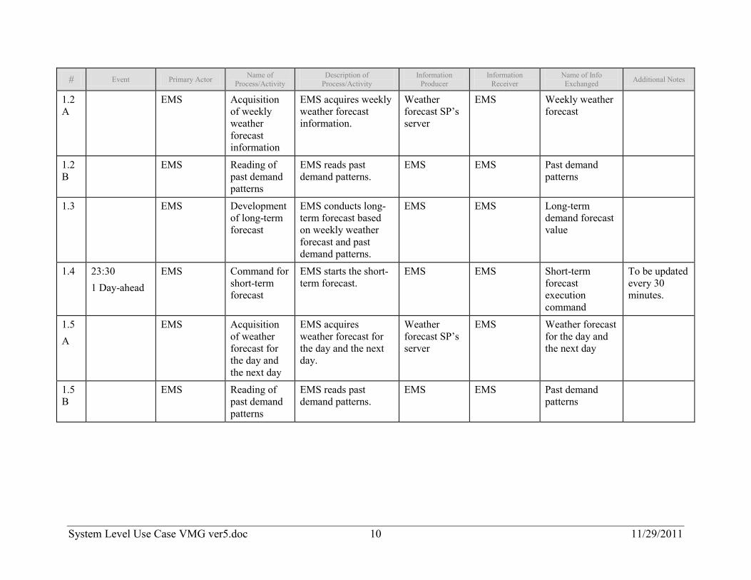
# Event Primary Actor Name of Process/Activity
Description of Process/Activity
Information Producer
Information Receiver
Name of Info Exchanged Additional Notes
1.2A
EMS Acquisition of weekly weather forecast information
EMS acquires weekly weather forecast information.
Weather forecast SP’s server
EMS Weekly weather forecast
1.2B
EMS Reading of past demand patterns
EMS reads past demand patterns.
EMS EMS Past demand patterns
1.3 EMS Development of long-term forecast
EMS conducts long-term forecast based on weekly weather forecast and past demand patterns.
EMS EMS Long-term demand forecast value
1.4 23:30 1 Day-ahead
EMS Command for short-term forecast
EMS starts the short-term forecast.
EMS EMS Short-term forecast execution command
To be updated every 30 minutes.
1.5 A
EMS Acquisition of weather forecast for the day and the next day
EMS acquires weather forecast for the day and the next day.
Weather forecast SP’s server
EMS Weather forecast for the day and the next day
1.5B
EMS Reading of past demand patterns
EMS reads past demand patterns.
EMS EMS Past demand patterns

System Level Use Case VMG ver5.doc 11 11/29/2011
# Event Primary Actor Name of Process/Activity
Description of Process/Activity
Information Producer
Information Receiver
Name of Info Exchanged Additional Notes
1.6 EMS Development of short-term forecast
EMS conducts short-term forecast based on the weather forecast for the day and the next day and past demand patterns.
EMS EMS Short-term demand forecast value Short-term intermittent generation output forecast value
1.7 EMS Development of generation scheduling
EMS develops generation scheduling.
EMS EMS Generation scheduling
2.1.3 Post-conditions and Significant Results
Actor/Activity Post-conditions Description and Results
EMS EMS possesses generation scheduling of controllable generators.
2.2 Steps to implement Stage 2 – Supply/demand control to achieve simultaneous balancing
2.2.1 Preconditions and Assumptions Actor/System/Information/Contract Preconditions or Assumptions
EMS EMS possesses generation scheduling.
Communication server
All RTUs
All RTUs involved in the VMG have a time synchronization function.
Each RTU is in an environment where they can communicate with communication server to upload the information to the communication server.

System Level Use Case VMG ver5.doc 12 11/29/2011
2.2.2 Steps – Supply/demand control to achieve simultaneous balancing # Event Primary Actor Name of
Process/Activity Description of
Process/Activity Information Producer Information Receiver
Name of Info Exchanged Additional Notes
2.1A
On-going Monitoring Data by Communication server
Communication server
Acquisition of power consumption of load
Communication server acquires power consumption of load.
End-user RTU. Communication server
Power consumption of load
2.1B
On-going Monitoring Data by Communication server
Communication server
Acquisition of generation power of intermittent renewables
Communication server acquires generation power of intermittent renewables.
Intermittent Renewables RTU
Communication server
Generation power of intermittent renewables.
2.1C
On-going Monitoring Data by Communication server
Communication server
Acquisition of generation power of controllable generators.
Communication server acquires generation power of controllable generators.
Controllable generator’s RTU
Communication server
Generation power of controllable generators
2.2 Communication server
Alignment of RTU data
Communication server organizes the data obtained from RTUs in chronological order.
Communication server
Communication server
Power consumption of load, generation power of intermittent renewables, generation power of controllable generators
2.3 Communication server
Calculation of supply- demand imbalance
Communication server calculates supply-demand imbalance.
Communication server
Communication server
Supply-demand imbalance

System Level Use Case VMG ver5.doc 13 11/29/2011
# Event Primary Actor Name of Process/Activity
Description of Process/Activity Information Producer Information
Receiver Name of Info Exchanged Additional Notes
2.4 Communication server
Transmission of supply-demand imbalance to EMS
Communication server transmits supply-demand imbalance to EMS.
Communication server
EMS Supply-demand imbalance
2.5 EMS Generation of Output reference of controllable generators
EMS generates output reference of controllable generators based on supply-demand imbalance and generation scheduling.
EMS EMS Output reference
2.6 EMS Output command
EMS transmits output command to the controller of controllable generator.
EMS Controllable generator’s controller
Output reference
2.2.3 Post-conditions and Significant Results
Actor/Activity Post-conditions Description and Results
Controllable generator Output is controlled so that controllable generator can achieve simultaneous balancing for a short amount of time, e.g. up to 10 minutes.
Entire VMG System Simultaneous balancing of supply and demand for a short amount of time, e.g. up to 10 minutes, is achieved across the entire VMG system.

System Level Use Case VMG ver5.doc 14 11/29/2011
3 Auxiliary Issues
3.1 References and contacts
ID Title or contact Reference or contact information
[1] The technologies supporting distributed energy system (in Japanese)
Fuji Electric Co., Ltd.
http://www.fujielectric.co.jp/company/jihou_archives/pdf/78-06/FEJ-78-06-423-2005.pdf
[2]
3.2 Action Item List
ID Description Status
[1]
[2]
3.3 Revision History
No Date Author Description
0.0 8-26-2011 H. Irie
H. Maejima
Draft for Review 1
1.0 9-18-2011 H. Irie
H. Maejima
Draft for Review 2
2.0 9-20-2011 J. Reilly Modified Draft

System Level Use Case VMG ver5.doc 15 11/29/2011
No Date Author Description
3.0 9-30-2011 S. Nii
T. Ohta
Review in terms of detailed description
4.0 10-17-2011 H. Irie
H. Maejima
Update Draft
5.0 11-18-2011 J. Reilly
H. Irie
Final Version