1 descriptions of function - eprismartgrid.epri.com/usecases/mpqm uc sen1.pdf1 descriptions of...
TRANSCRIPT
MPQM UC SEN1 1 9/13/2012
Sendai Use Case Microgrid to Supply Power at Multiple Power Quality Levels
(NEDO Sendai Project) Version 3.2 4 Sep, 2012
1 Descriptions of Function 1.1 Function Name Multi Power Quality Microgrid (MPQM)
1.2 Function ID System Level Use Case SEN-1
1.3 Brief Description This use case describes a Microgrid that enables the supply of power to critical loads at multiple levels of power quality, a Multi Power Quality Microgrid (MPQM). These critical loads require higher levels of power quality than are supplied normally by the distribution utility. The Microgrid does this by utilizing Distributed Energy Resources (DER)) and power from the distribution utility (grid) in a mutually complementary manner.
Concept of MPQM The MPQM is a system that combines distributed energy resources (DER), an Integrated Power Supply (IPS ) and a Dynamic Voltage Restorer (DVR)) to supply loads within the Microgrid at multiple levels of power quality.
The concept behind the MPQM is to provide power at multiple levels of quality according to customer needs at a given point in time. It involves the complementary interworking of distributed power sources, including solar power generation systems, and existing power systems, as well as efficient use of batteries and power electronics.

MPQM UC SEN1 2 9/13/2012
The concept of the MPQM is described in the diagram in Figure 1 below.
A ClassLoad
A ClassLoad
A ClassLoad
NormalClassLoad
NormalClassLoad
NormalClassLoad
B ClassLoad
B ClassLoad
B ClassLoad
DVR IPS
Grid Power DGs
Optimized operation between the grid power and DGs
Power Quality ImprovementNormal
Quality
A Class Quality SystemB Class Quality System
SWITCH1 SWITCH2
Figure 1 Concept of MPQM
The MPQM comprises three types of distributed generation, fuel cells, gas engines and photovoltaic panels. These are supported by a dynamic voltage restorer (DVR) and integrated power supply (IPS) for power compensation to two levels of power quality, A-Class and B-Class. A “normal” class of power quality is served directly by grid power (distribution utility). The MPQM has two switches, Switch 1 between the MPQM and grid at the PCC and Switch 2 within the MPQM.
MPQM UC SEN1 3 9/13/2012
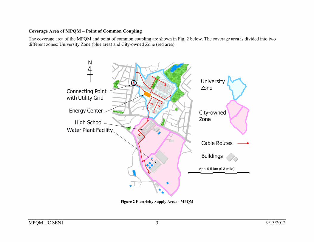
Coverage Area of MPQM – Point of Common Coupling The coverage area of the MPQM and point of common coupling are shown in Fig. 2 below. The coverage area is divided into two different zones: University Zone (blue area) and City-owned Zone (red area).
App. 0.5 km (0.3 mile)
High SchoolWater Plant Facility
Connecting Point with Utility Grid
Cable Routes
Buildings
N
University Zone
City-owned Zone
Energy Center
Figure 2 Electricity Supply Areas - MPQM

MPQM UC SEN1 4 9/13/2012
The PCC between the MPQM and the grid is located in the blue area. Power from the grid cannot be transmitted to the red area due rules on the “resale of electricity” in the interconnection agreement with the local utility (Tohoku Electric Power Co.). Therefore, a “resale prevention” relay is installed to control the power flow, as shown in Fig. 3.
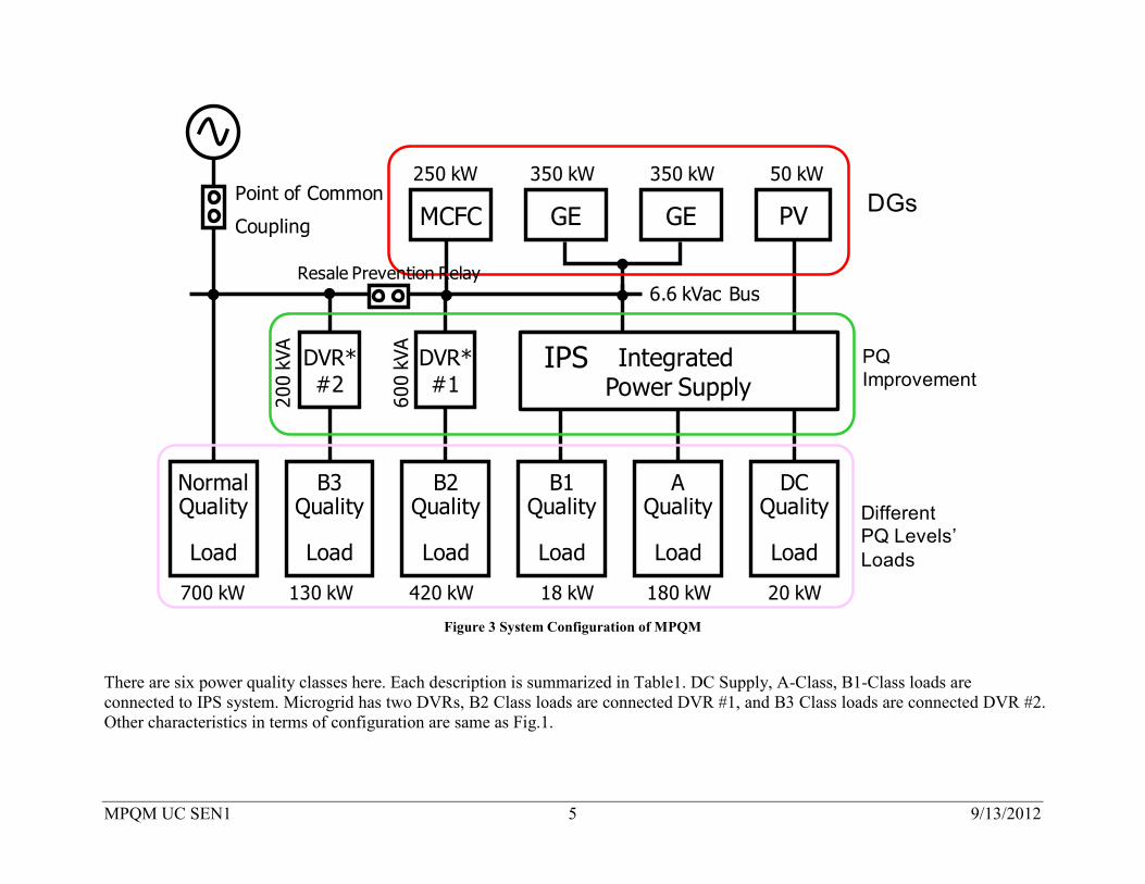
System Configuration of MPQM The system configuration of the MPQM is shown in Fig. 3. This diagram shows four classes of power quality: (1) A-Class, (2) B-Class, (3) Normal Class and (4) DC. B-CLASS is divided into three classes (B1, B2 and B3). DC has power quality equivalent to A-CLASS.
MPQM UC SEN1 5 9/13/2012
DVR*#2
NormalQuality
Load
B3Quality
Load
130 kW700 kW
350 kW350 kW 50 kW
18 kW
6.6 kVac Bus
Point of Common
Coupling PVGE GE
250 kW
MCFC
420 kW
B1Quality
Load
DVR*#1
B2Quality
Load
20 kW180 kW
AQuality
Load
DCQuality
Load
Integrated Power Supply
IPS
200
kVA
600
kVA
DGs
PQImprovement
DifferentPQ Levels’Loads
Resale Prevention Relay
Figure 3 System Configuration of MPQM
There are six power quality classes here. Each description is summarized in Table1. DC Supply, A-Class, B1-Class loads are connected to IPS system. Microgrid has two DVRs, B2 Class loads are connected DVR #1, and B3 Class loads are connected DVR #2. Other characteristics in terms of configuration are same as Fig.1.

MPQM UC SEN1 6 9/13/2012
The MPQM is connected to the power grid at one point via a circuit breaker (CB1). Basically, it functions through the interworking of three types of distributed power sources (two 350 kW gas engine generator sets, a 250 kW molten carbonate fuel cell, and a 50 kWp solar photovoltaic panel). The output of photovoltaic generation depends exclusively on weather, independent from other controllable generation outputs.
Integrated Power Supply
PV AC Power Source
BatteryACSW
Bypass Circuit
Byp
ass
Circ
uit
50 kWp
DCDC
50 kW 600 Ah
DC Bus430 Vdc
DCAC
ALoad
B1Load
DCLoad
ACDC
DCDC
300 Vdc
BidirectionalConverter20 kW
200 kVA(180 kW)
300 kVA(270 kW)
3P 400 Vac 3P 200 Vac
Figure 4 Block Diagram of Integrated Power Supply
MPQM UC SEN1 7 9/13/2012
The IPS comprises a bidirectional power converter (AC ⇔ DC), a DC-AC inverter, a DC-DC converter (PV) for powering the load, a semiconductor switch (ACSW), and a sealed lead acid battery. There is another DC-DC converter for powering in the IPS. All converters and the battery are connected on the DC-bus in the IPS. The DC-DC (load) and DC-AC converters consume electric power as loads, and the bidirectional and DC-DC (PV) converters supply power. The battery adjusts the power supply on the DC bus.
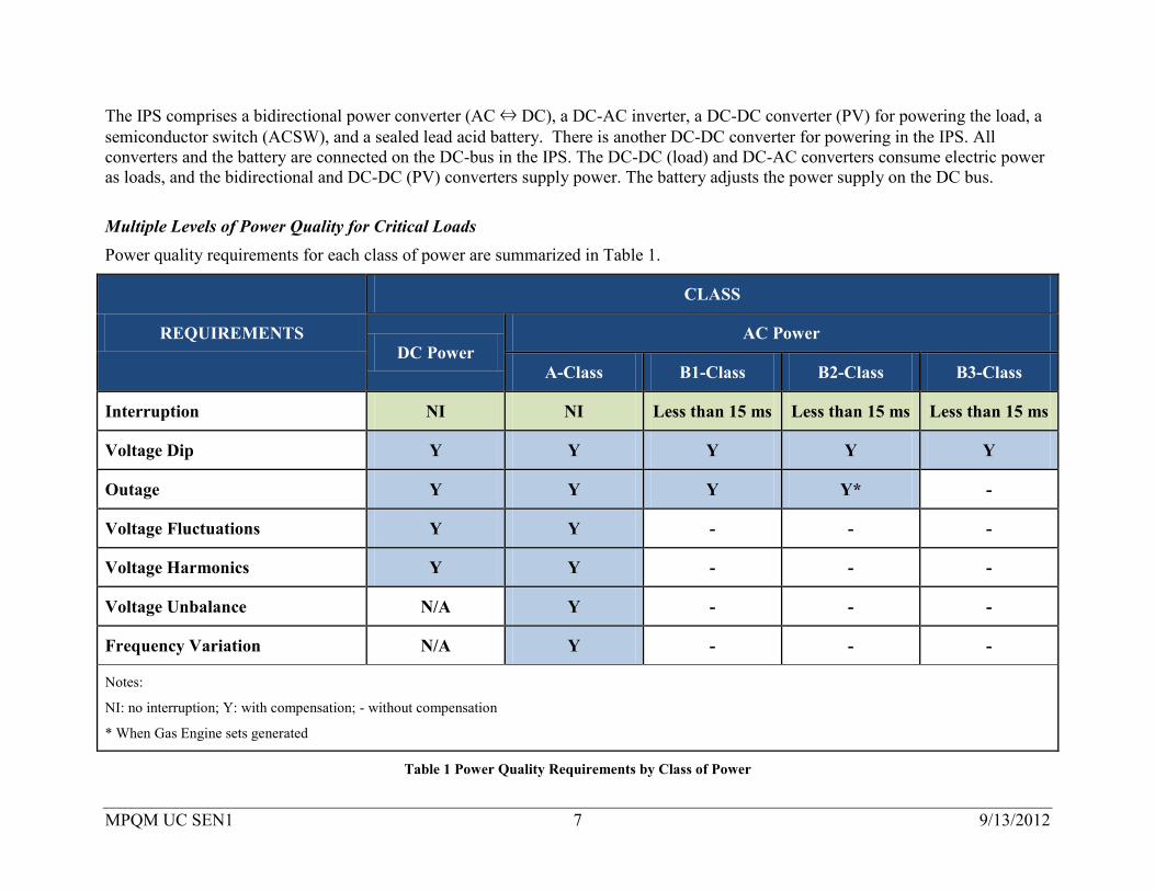
Multiple Levels of Power Quality for Critical Loads Power quality requirements for each class of power are summarized in Table 1.
REQUIREMENTS
CLASS
DC Power AC Power
A-Class B1-Class B2-Class B3-Class
Interruption NI NI Less than 15 ms Less than 15 ms Less than 15 ms
Voltage Dip Y Y Y Y Y
Outage Y Y Y Y* -
Voltage Fluctuations Y Y - - -
Voltage Harmonics Y Y - - -
Voltage Unbalance N/A Y - - -
Frequency Variation N/A Y - - -
Notes:
NI: no interruption; Y: with compensation; - without compensation
* When Gas Engine sets generated
Table 1 Power Quality Requirements by Class of Power
MPQM UC SEN1 8 9/13/2012
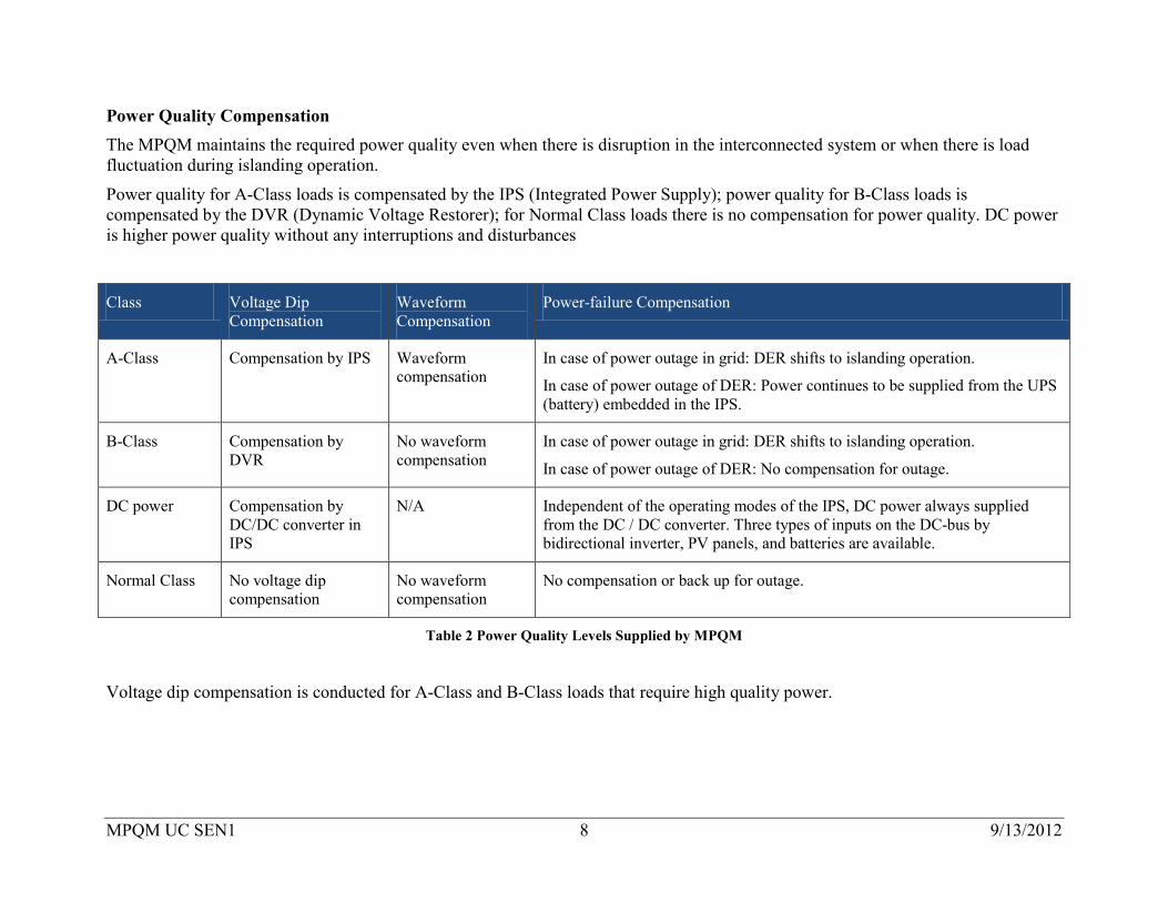
Power Quality Compensation The MPQM maintains the required power quality even when there is disruption in the interconnected system or when there is load fluctuation during islanding operation.
Power quality for A-Class loads is compensated by the IPS (Integrated Power Supply); power quality for B-Class loads is compensated by the DVR (Dynamic Voltage Restorer); for Normal Class loads there is no compensation for power quality. DC power is higher power quality without any interruptions and disturbances
Class Voltage Dip Compensation
Waveform Compensation
Power-failure Compensation
A-Class Compensation by IPS Waveform compensation
In case of power outage in grid: DER shifts to islanding operation.
In case of power outage of DER: Power continues to be supplied from the UPS (battery) embedded in the IPS.
B-Class Compensation by DVR
No waveform compensation
In case of power outage in grid: DER shifts to islanding operation.
In case of power outage of DER: No compensation for outage.
DC power Compensation by DC/DC converter in IPS
N/A Independent of the operating modes of the IPS, DC power always supplied from the DC / DC converter. Three types of inputs on the DC-bus by bidirectional inverter, PV panels, and batteries are available.
Normal Class No voltage dip compensation
No waveform compensation
No compensation or back up for outage.
Table 2 Power Quality Levels Supplied by MPQM
Voltage dip compensation is conducted for A-Class and B-Class loads that require high quality power.
MPQM UC SEN1 9 9/13/2012
◆A-CLASS
A-CLASS power quality is supplied constantly at voltage waveform level for the most important loads that require power to be supplied without any problem such as distortion, flicker, harmonics. When there is a power failure in the grid, DER shifts its operation to DER-Islanding Mode. Even when the power supply from the DER is no longer available, the power feed is switched instantaneously to Battery-Supply Mode, thus continuing the feed without interruption.
The IPS is a system for compensation of power quality to Class A loads. It has three operational modes:
• Grid-Connection Mode compensates voltage dip of A-class loads when the MPQM is interconnected with the distribution system.
• DER-Islanding Mode supplies electricity to A-class load from the DER in the event of distribution system outages.
• Battery-Supply Mode supplies electricity to A-class load from the battery embedded in the IPS when DER stops.
◆B-CLASS
B-CLASS power quality is supplied by combining the DVR (Dynamic Voltage Restorer) with STATCOM, capacitor. When there is a power failure in the grid, DER shifts to an islanding operation, as in the case of A-CLASS when the power supply from DER is interrupted.
◆Normal CLASS
Normal Class power quality is supplied at a power quality level equivalent to that of the distribution utility.
MPQM has two switches, “Switch 1” at the PCC and “Switch 2” that separates Normal Class from A and B Classes. These switches operate to manage the islanding operation of the MPQM when there is an outage on the grid.
NOTE: The MPQM was conceived as a research demonstration project, Sendai Demonstration of Multiple Power Quality Supply System by the New Energy and Technology Development Organization (NEDO) in 2004. The MPQM was installed at Tohoku Fukushi University, Sendai, Miyagi Prefecture, Japan. The research was conducted by NTT Facilities, Inc. (NTT-F); the Microgrid continues operations under the management of NTT-F.
MPQM UC SEN1 10 9/13/2012
1.4 Narrative The MPQM is designed to supply power to customers at the level of power quality that meets their needs. The MPQM can continue to supply power at a high power quality level when the DER is grid-connected or when the grid suffers from an outage and the DER is in an islanding operation mode.
The functions of the MPQM can be described in four stages as follows:
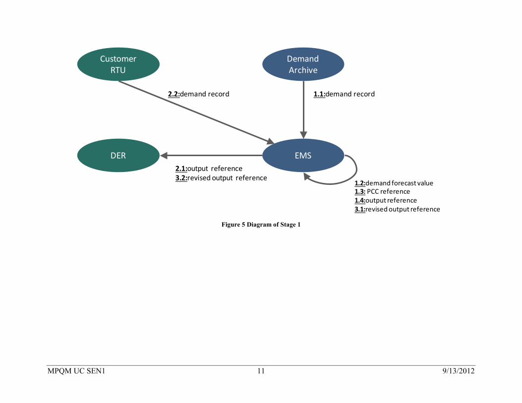
Stage 1: DEMAND AND GENERATION DAY-AHEAD FORECAST, GENERATION SCHEDULING AND OPERATING DAY ADJUSTMENTS The MPQM utilizes power from the DER in a mutually complementary manner with the distribution system by scheduling generation according to forecasted demand, adjusted for real time operations. In the MPQM the EMS calculates the Day-Ahead demand forecast (half-hourly, for twenty-four (24) hour period prior to the beginning of the Operating Day); prepares a generation schedule; and reviews and adjusts generation on the Operating Day, the actual day, including hours ending 0100 to 2400, during which energy is flowing. The forecasts are made in the EMS by using archives of load profiles provided the previous day based on past month records.
Based on the demand forecast and the PCC reference value, the monitoring and control server plans a Day-Ahead target output value (half-hourly, for 24 hours) for DER. . This target output value is then conveyed to the DER as a command.
The demand forecast value is reviewed on the Operating Day. If there is a gap between the demand forecast value and the actual demand record obtained from RTU installed in the load, the generation schedule incorporating the target output value for the DER is adjusted.
The interconnection agreement between the microgrid and distribution utility has a provision that prohibits the reverse power flow from the MPQM to the grid. In accordance with this provision, a reference value is set for power flow at the PCC and incorporated into the operation schedule of the DER.
MPQM UC SEN1 11 9/13/2012
EMS
Demand Archive
DER
1.1:demand record
1.2:demand forecast value1.3: PCC reference1.4:output reference3.1:revised output reference
Customer RTU
2.1:output reference3.2:revised output reference
2.2:demand record
Figure 5 Diagram of Stage 1

MPQM UC SEN1 12 9/13/2012
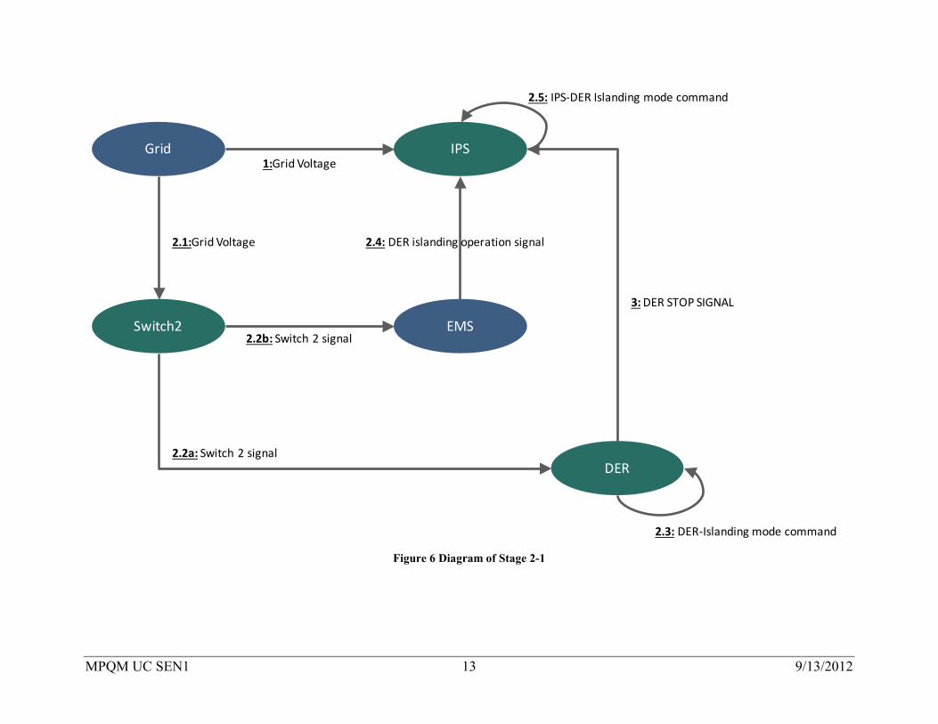
Stage 2-1: A-CLASS POWER QUALITY SUPPLY For the A-CLASS POWER QUALITY SUPPLY, power quality is compensated constantly at voltage waveform level by the IPS. Even when the power supply from the DER or commercial grid is no longer available, feeding is continued without interruption by switching the operation instantaneously to the back-up system of the IPS which contains a UPS (battery). This function is implemented by the IPS.
The IPS has three operation modes: i) Grid-Connection Mode, ii) DER--Islanding Mode and iii) Battery-Supply Mode. Usually, it is operated in Grid-Connection Mode.
• Grid-Connection Mode compensates voltage dip of A-class loads when the MPQM is interconnected with the distribution system.
• DER-Islanding Mode supplies electricity to A-class loads in collaboration with DER Distribution system during distribution system outages.
• Battery-Supply Mode supplies electricity to A-class from the battery embedded in the IPS when DER stops. When the IPS detects a dip in grid voltage, it shifts into Battery-Supply Mode and discharges the storage battery to supply power to A-CLASS loads.
In case of a power outage in the distribution utility, Switch 2 is opened as soon as it detects the outage. Once the DER detects the opening of Switch 2, it shifts to DER-Islanding Mode. Once the EMS detects that Switch 2 is open, it sends a command to the IPS to shift to DER-Islanding Mode. The IPS in DER-Islanding Mode starts supplying power to A-CLASS loads in collaboration with the DER and IPS.
If the DER fails due to an accident or malfunction, while in Islanding Mode, the IPS receives a stop signal, shifts to Battery-Supply Mode and starts discharging the storage battery to feed power to A-CLASS loads.
MPQM UC SEN1 13 9/13/2012
DER
IPS1:Grid Voltage
Grid
Switch2
2.1:Grid Voltage
EMS
2.2a: Switch 2 signal
2.3: DER-Islanding mode command
2.2b: Switch 2 signal
2.4: DER islanding operation signal
2.5: IPS-DER Islanding mode command
3: DER STOP SIGNAL
Figure 6 Diagram of Stage 2-1
MPQM UC SEN1 14 9/13/2012
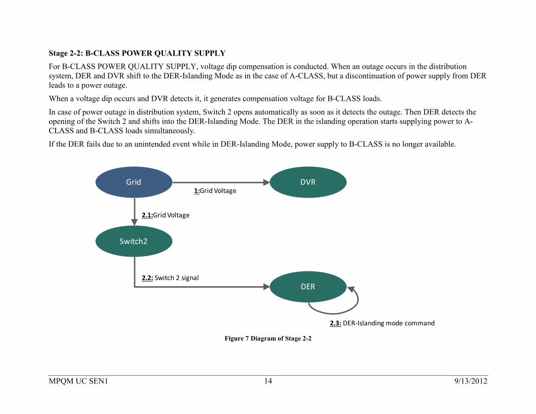
Stage 2-2: B-CLASS POWER QUALITY SUPPLY For B-CLASS POWER QUALITY SUPPLY, voltage dip compensation is conducted. When an outage occurs in the distribution system, DER and DVR shift to the DER-Islanding Mode as in the case of A-CLASS, but a discontinuation of power supply from DER leads to a power outage.
When a voltage dip occurs and DVR detects it, it generates compensation voltage for B-CLASS loads.
In case of power outage in distribution system, Switch 2 opens automatically as soon as it detects the outage. Then DER detects the opening of the Switch 2 and shifts into the DER-Islanding Mode. The DER in the islanding operation starts supplying power to A-CLASS and B-CLASS loads simultaneously.
If the DER fails due to an unintended event while in DER-Islanding Mode, power supply to B-CLASS is no longer available.
DER
DVR1:Grid Voltage
Grid
Switch2
2.1:Grid Voltage
2.2: Switch 2 signal
2.3: DER-Islanding mode command Figure 7 Diagram of Stage 2-2

MPQM UC SEN1 15 9/13/2012
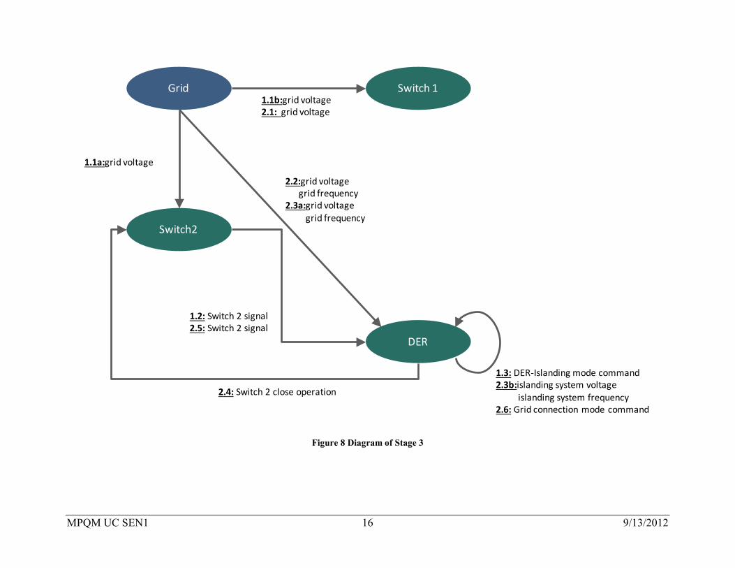
Stage 3: AUTOMATIC SHIFT TO ISLANDING OPERATION AT GRID OUTAGE, AND AUTOMATIC SHIFT TO CONNECTED OPERATION AT GRID RESTORATION Stage 3-1: AUTOMATIC SHIFT TO ISLANDING OPERATION AT GRID OUTAGE The MPQM is in grid-connected operation at normal times. When there is an outage in grid, Switch 2 promptly detects the outage from grid voltage information and opens. In the same way, Switch 1 opens. As soon as Switch 2 opens, DER shifts to Islanding Mode.
Stage 3-2: AUTOMATIC SHIFT TO CONNECTED OPERATION AT GRID RESTORATION When the distribution utility restores power at the PCC, Switch 1 detects the change of voltage and closes. The DER then synchronizes the voltage and frequency of the islanding system with the grid’s voltage and frequency. DER closes Switch 2 as soon as it detects that voltage/frequency is synchronized between the islanding system and grid.
MPQM UC SEN1 16 9/13/2012
DER
Switch 11.1b:grid voltage2.1: grid voltage
Grid
Switch2
1.1a:grid voltage
1.2: Switch 2 signal2.5: Switch 2 signal
1.3: DER-Islanding mode command2.3b:islanding system voltage
islanding system frequency2.6: Grid connection mode command
2.2:grid voltagegrid frequency
2.3a:grid voltagegrid frequency
2.4: Switch 2 close operation
Figure 8 Diagram of Stage 3
MPQM UC SEN1 17 9/13/2012
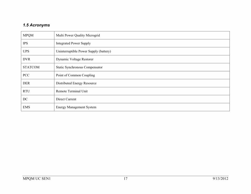
1.5 Acronyms
MPQM Multi Power Quality Microgrid
IPS Integrated Power Supply
UPS Uninterruptible Power Supply (battery)
DVR Dynamic Voltage Restorer
STATCOM Static Synchronous Compensator
PCC Point of Common Coupling
DER Distributed Energy Resource
RTU Remote Terminal Unit
DC Direct Current
EMS Energy Management System
MPQM UC SEN1 18 9/13/2012
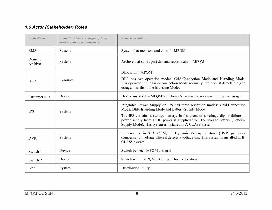
1.6 Actor (Stakeholder) Roles
Actor Name Actor Type (person, organization, device, system, or subsystem)
Actor Description
EMS System System that monitors and controls MPQM
Demand Archive System Archive that stores past demand record data of MPQM
DER Resource
DER within MPQM
DER has two operation modes: Grid-Connection Mode and Islanding Mode. It is operated in the Grid-Connection Mode normally, but once it detects the grid outage, it shifts to the Islanding Mode.
Customer RTU Device Device installed in MPQM’s customer’s premise to measure their power usage
IPS
System
Integrated Power Supply or IPS has three operation modes: Grid-Connection Mode, DER-Islanding Mode and Battery-Supply Mode
The IPS contains a storage battery. In the event of a voltage dip or failure in power supply from DER, power is supplied from the storage battery (Battery-Supply Mode). This system is installed in A-CLASS system.
DVR System Implemented in STATCOM, the Dynamic Voltage Restorer (DVR) generates compensation voltage when it detects a voltage dip. This system is installed in B-CLASS system.
Switch 1 Device Switch between MPQM and grid
Switch 2 Device Switch within MPQM. See Fig. 1 for the location
Grid System Distribution utility

MPQM UC SEN1 19 9/13/2012
1.7 Information exchanged
Information Object Name Information Object Description
demand record Demand record is the data to be measured by customer RTU and stored in Demand Archive.
demand forecast value Future demand forecast calculated by EMS.
PCC REFERENCE Target power flow value at PCC in MPQM.
output reference Output reference of DER (prepared by EMS).
revised output reference EMS reviews and revises the output reference for DER; when there is a gap between the demand forecast value and the actual result, a revised output reference is set.
Grid Voltage Voltage in distribution system.
Grid frequency Frequency in distribution system.
DER-ISLANDING MODE COMMAND
Command within DER. Based on this command, DER shifts into Islanding Mode.
IPS-DER ISLANDING MODE COMMAND
Command within IPS. Based on this command, IPS shifts into DER-Islanding Mode.
DER STOP SIGNAL Signal to inform IPS that DER stopped.
Switch 2 signal Signal to inform open/close status of Switch 2.
Islanding system voltage Voltage of islanding system when DER is in islanding operation mode.
Islanding system frequency Frequency of islanding system when DER is in islanding operation mode.
Switch 2 Close Operation Operational Signal of Closing Switch 2 from DER.

MPQM UC SEN1 20 9/13/2012
1.8 Activities/Services
Activity/Service Name Activities/Services Provided
A-CLASS POWER QUALITY SUPPLY
A-CLASS POWER QUALITY SUPPLY provides power quality compensation at voltage waveform level on a constant basis. Even when the power supply from the DER or grid is no longer available, the feeding can be continued by switching to the back-up system without any interruption.
B-CLASS POWER QUALITY SUPPLY
B-CLASS POWER QUALITY SUPPLY provides voltage dip compensation. In case of grid outage, DER shifts into the islanding mode as in the case of A-CLASS, but the power goes out when the supply from DER is no longer available.
1.9 Contracts/Regulations
Contract/Regulation Impact of Contract/Regulation on Function
Contract with A-CLASS customer MPQM operator has a contract with A-CLASS customer to provide A-CLASS power supply.
Contract with B-CLASS customer MPQM operator has a contract with B-CLASS customer to provide B-CLASS power supply.
Interconnection Agreement with distribution utility
There is an interconnection agreement on reverse power flow prevention between the distribution utility and MPQM owner/operator.
MPQM UC SEN1 21 9/13/2012
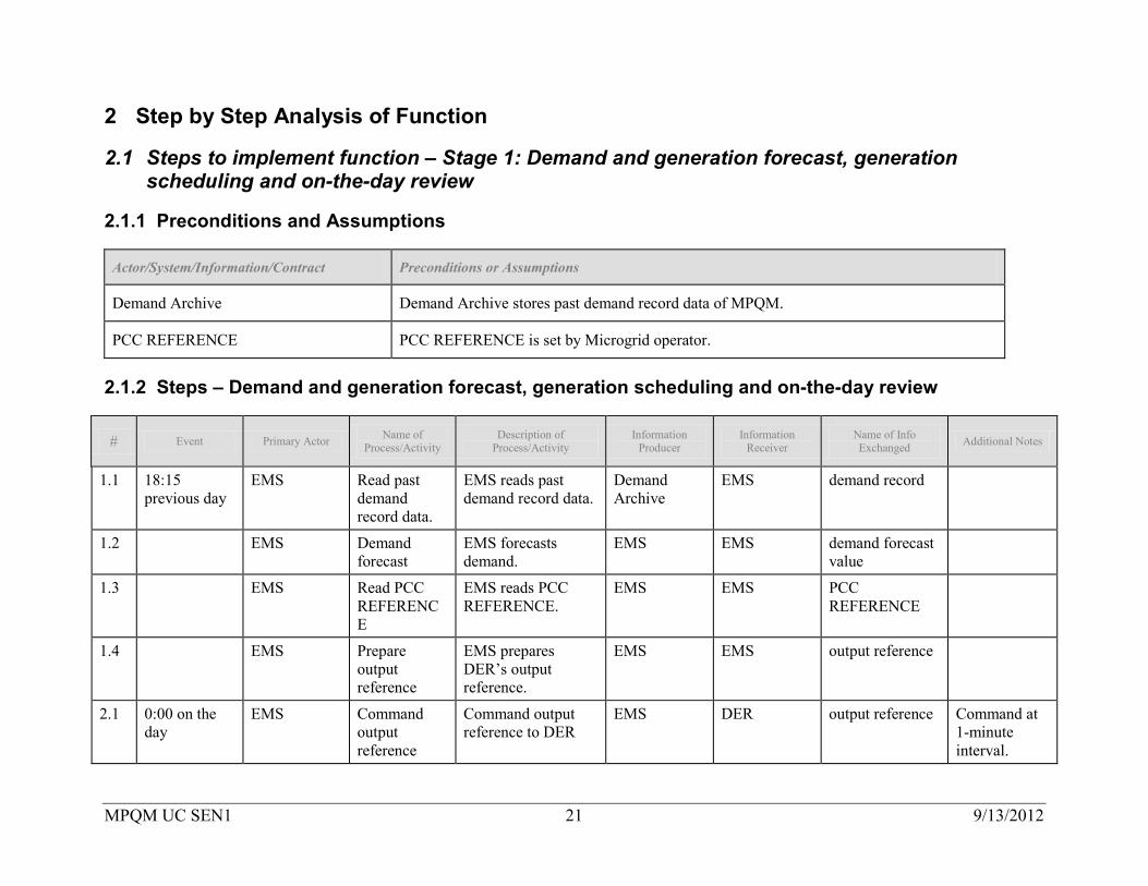
2 Step by Step Analysis of Function
2.1 Steps to implement function – Stage 1: Demand and generation forecast, generation scheduling and on-the-day review
2.1.1 Preconditions and Assumptions
Actor/System/Information/Contract Preconditions or Assumptions
Demand Archive Demand Archive stores past demand record data of MPQM.
PCC REFERENCE PCC REFERENCE is set by Microgrid operator.
2.1.2 Steps – Demand and generation forecast, generation scheduling and on-the-day review
# Event Primary Actor Name of Process/Activity
Description of Process/Activity
Information Producer
Information Receiver
Name of Info Exchanged Additional Notes
1.1 18:15 previous day
EMS Read past demand record data.
EMS reads past demand record data.
Demand Archive
EMS demand record
1.2 EMS Demand forecast
EMS forecasts demand.
EMS EMS demand forecast value
1.3 EMS Read PCC REFERENCE
EMS reads PCC REFERENCE.
EMS EMS PCC REFERENCE
1.4 EMS Prepare output reference
EMS prepares DER’s output reference.
EMS EMS output reference
2.1 0:00 on the day
EMS Command output reference
Command output reference to DER
EMS DER output reference Command at 1-minute interval.

MPQM UC SEN1 22 9/13/2012
# Event Primary Actor Name of Process/Activity
Description of Process/Activity
Information Producer
Information Receiver
Name of Info Exchanged Additional Notes
2.2 EMS Collect demand record
Collect demand record obtained from customer RTU
customer RTU
EMS demand record
3.1 When there is a gap between the demand forecast and actual result.
EMS Review output reference
Recalculate output reference for DER in consideration of the gap between demand forecast and actual result.
EMS EMS revised output reference
3.2 EMS Command revised output reference
Command revised output reference to DER.
EMS DER revised output reference
Command at 1-minute interval.
2.1.3 Post-conditions and Significant Results
Actor/Activity Post-conditions Description and Results
MPQM MPQM maintains stable supply inside because it is provided power from the DER and grid in a mutually complementary manner (between DER and grid).
2.2 Steps to implement function – Stage 2-1: A-CLASS POWER QUALITY SUPPLY
2.2.1 Preconditions and Assumptions Actor/System/Information/Contract Preconditions or Assumptions
Grid and MPQM Grid and MPQM are operated connected to each other.
DER DER is operated normally.
MPQM UC SEN1 23 9/13/2012
Actor/System/Information/Contract Preconditions or Assumptions
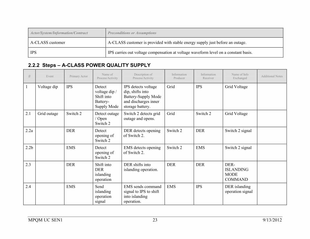
A-CLASS customer A-CLASS customer is provided with stable energy supply just before an outage.
IPS IPS carries out voltage compensation at voltage waveform level on a constant basis.
2.2.2 Steps – A-CLASS POWER QUALITY SUPPLY
# Event Primary Actor Name of Process/Activity
Description of Process/Activity
Information Producer
Information Receiver
Name of Info Exchanged Additional Notes
1 Voltage dip IPS Detect voltage dip / Shift into Battery-Supply Mode
IPS detects voltage dip, shifts into Battery-Supply Mode and discharges inner storage battery.
Grid IPS Grid Voltage
2.1 Grid outage Switch 2 Detect outage / Open Switch 2
Switch 2 detects grid outage and opens.
Grid Switch 2 Grid Voltage
2.2a DER Detect opening of Switch 2
DER detects opening of Switch 2.
Switch 2 DER Switch 2 signal
2.2b EMS Detect opening of Switch 2
EMS detects opening of Switch 2.
Switch 2 EMS Switch 2 signal
2.3 DER Shift into DER islanding operation
DER shifts into islanding operation.
DER DER DER-ISLANDING MODE COMMAND
2.4 EMS Send islanding operation signal
EMS sends command signal to IPS to shift into islanding operation.
EMS IPS DER islanding operation signal

MPQM UC SEN1 24 9/13/2012
# Event Primary Actor Name of Process/Activity
Description of Process/Activity
Information Producer
Information Receiver
Name of Info Exchanged Additional Notes
2.5 IPS Shift into control mode for IPS islanding operation
IPS shifts into DER-ISLANDING MODE.
IPS IPS IPS-DER ISLANDING MODE COMMAND
3 DER stops when in DER islanding operation
IPS Detect DER stoppage / Shift into Battery-Supply Mode
IPS detects DER stoppage, enters into Battery-Supply Mode and discharges the inner storage battery.
DER IPS DER STOP SIGNAL
2.2.3 Post-conditions and Significant Results
Actor/Activity Post-conditions Description and Results
A-CLASS customer A-CLASS customer is provided with stable power supply even in the event of voltage dip, grid outage and/or DER stoppage.
2.3 Steps to implement function – Stage 2-2: B-CLASS POWER QUALITY SUPPLY
2.3.1 Preconditions and Assumptions Actor/System/Information/Contract Preconditions or Assumptions
Grid and MPQM Grid and MPQM are operated connected to each other.
B-CLASS customer B-CLASS customer is provided with stable energy supply just before a voltage dip.
MPQM UC SEN1 25 9/13/2012
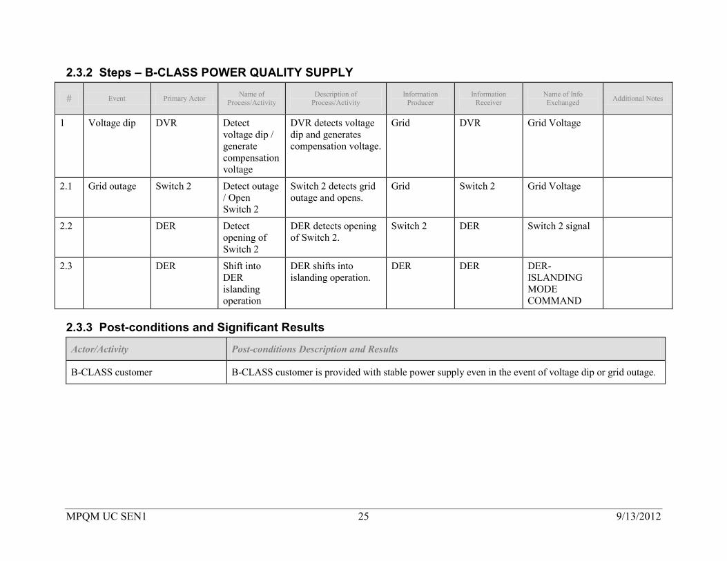
2.3.2 Steps – B-CLASS POWER QUALITY SUPPLY
# Event Primary Actor Name of Process/Activity
Description of Process/Activity
Information Producer
Information Receiver
Name of Info Exchanged Additional Notes
1 Voltage dip DVR Detect voltage dip / generate compensation voltage
DVR detects voltage dip and generates compensation voltage.
Grid DVR Grid Voltage
2.1 Grid outage Switch 2 Detect outage / Open Switch 2
Switch 2 detects grid outage and opens.
Grid Switch 2 Grid Voltage
2.2 DER Detect opening of Switch 2
DER detects opening of Switch 2.
Switch 2 DER Switch 2 signal
2.3 DER Shift into DER islanding operation
DER shifts into islanding operation.
DER DER DER-ISLANDING MODE COMMAND
2.3.3 Post-conditions and Significant Results
Actor/Activity Post-conditions Description and Results
B-CLASS customer B-CLASS customer is provided with stable power supply even in the event of voltage dip or grid outage.
MPQM UC SEN1 26 9/13/2012
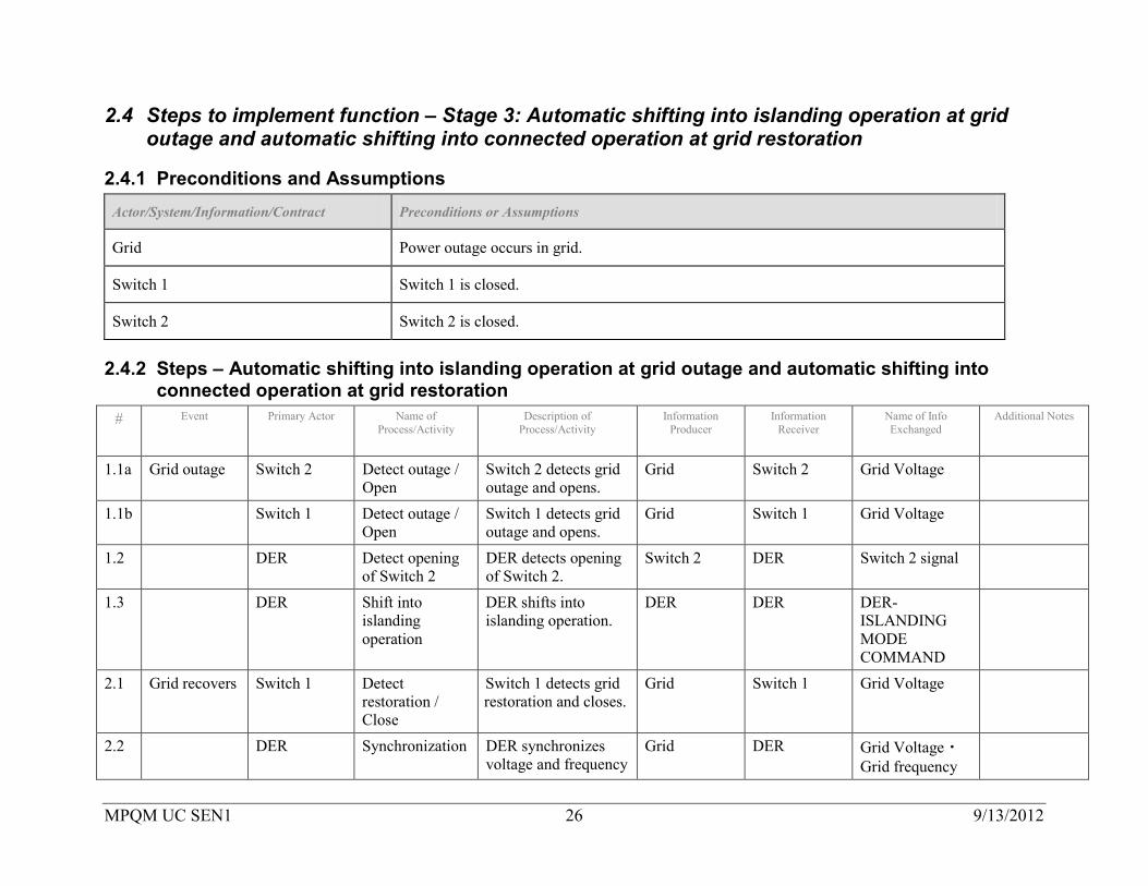
2.4 Steps to implement function – Stage 3: Automatic shifting into islanding operation at grid outage and automatic shifting into connected operation at grid restoration
2.4.1 Preconditions and Assumptions Actor/System/Information/Contract Preconditions or Assumptions
Grid Power outage occurs in grid.
Switch 1 Switch 1 is closed.
Switch 2 Switch 2 is closed.
2.4.2 Steps – Automatic shifting into islanding operation at grid outage and automatic shifting into connected operation at grid restoration
# Event Primary Actor Name of Process/Activity
Description of Process/Activity
Information Producer
Information Receiver
Name of Info Exchanged
Additional Notes
1.1a Grid outage Switch 2 Detect outage / Open
Switch 2 detects grid outage and opens.
Grid Switch 2 Grid Voltage
1.1b Switch 1 Detect outage / Open
Switch 1 detects grid outage and opens.
Grid Switch 1 Grid Voltage
1.2 DER Detect opening of Switch 2
DER detects opening of Switch 2.
Switch 2 DER Switch 2 signal
1.3 DER Shift into islanding operation
DER shifts into islanding operation.
DER DER DER-ISLANDING MODE COMMAND
2.1 Grid recovers Switch 1 Detect restoration / Close
Switch 1 detects grid restoration and closes.
Grid Switch 1 Grid Voltage
2.2 DER Synchronization DER synchronizes voltage and frequency
Grid DER Grid Voltage・Grid frequency

MPQM UC SEN1 27 9/13/2012
of islanding system to the grid.
2.3a DER Detect voltage and frequency of grid.
DER detects voltage and frequency of grid.
Grid DER Grid Voltage・Grid frequency
2.3b DER Detect voltage and frequency of islanding system.
DER detects voltage and frequency of islanding system.
DER DER Islanding system voltage・Islanding system frequency
2.4 DER Close Switch 2 DER closes Switch 2 on confirming the synchronization.
DER Switch 2 Switch 2 close operation
2.5 DER Detect closing of Switch 2
DER detects closing of Switch 2.
Switch 2 DER Switch 2 signal
2.6 DER Shift into grid connected operation
DER shifts into grid connected operation.
DER DER Grid-Connection Mode Command
2.4.3 Post-conditions and Significant Results
Actor/Activity Post-conditions Description and Results
Grid Grid restored.
Switch 1 Switch 1 is closed.
Switch 2 Switch 2 is closed.
MPQM UC SEN1 28 9/13/2012
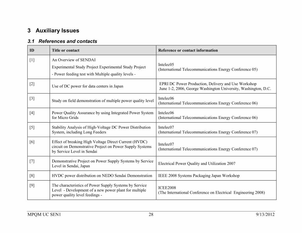
3 Auxiliary Issues
3.1 References and contacts
ID Title or contact Reference or contact information
[1] An Overview of SENDAI
Experimental Study Project Experimental Study Project
- Power feeding test with Multiple quality levels -
Intelec05 (International Telecommunications Energy Conference 05)
[2] Use of DC power for data centers in Japan EPRI DC Power Production, Delivery and Use Workshop June 1-2, 2006, George Washington University, Washington, D.C.
[3] Study on field demonstration of multiple power quality level Intelec06 (International Telecommunications Energy Conference 06)
[4] Power Quality Assurance by using Integrated Power System for Micro Grids
Intelec06 (International Telecommunications Energy Conference 06)
[5] Stability Analysis of High-Voltage DC Power Distribution System, including Long Feeders
Intelec07 (International Telecommunications Energy Conference 07)
[6] Effect of breaking High Voltage Direct Current (HVDC) circuit on Demonstrative Project on Power Supply Systems by Service Level in Sendai
Intelec07 (International Telecommunications Energy Conference 07)
[7] Demonstrative Project on Power Supply Systems by Service Level in Sendai, Japan Electrical Power Quality and Utilization 2007
[8] HVDC power distribution on NEDO Sendai Demonstration IEEE 2008 Systems Packaging Japan Workshop
[9] The characteristics of Power Supply Systems by Service Level - Development of a new power plant for multiple power quality level feedings -
ICEE2008 (The International Conference on Electrical Engineering 2008)
MPQM UC SEN1 29 9/13/2012
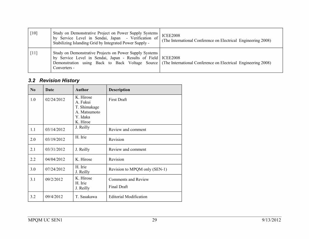
[10] Study on Demonstrative Project on Power Supply Systems by Service Level in Sendai, Japan - Verification of Stabilizing Islanding Grid by Integrated Power Supply -
ICEE2008 (The International Conference on Electrical Engineering 2008)
[11] Study on Demonstrative Projects on Power Supply Systems by Service Level in Sendai, Japan - Results of Field Demonstration using Back to Back Voltage Source Converters -
ICEE2008 (The International Conference on Electrical Engineering 2008)
3.2 Revision History
No Date Author Description
1.0 02/24/2012 K. Hirose A. Fukui T. Shimakage A. Matsumoto Y. Idaka K. Hiroe
First Draft
1.1 03/14/2012 J. Reilly Review and comment
2.0 03/19/2012 H. Irie Revision
2.1 03/31/2012 J. Reilly Review and comment
2.2 04/04/2012 K. Hirose Revision
3.0 07/24/2012 H. Irie J. Reilly Revision to MPQM only (SEN-1)
3.1 09/2/2012 K. Hirose H. Irie J. Reilly
Comments and Review
Final Draft
3.2 09/4/2012 T. Sasakawa Editorial Modification