1 emergency exit detector team kelly mdr presentation team members leonardo mascarenhas ernald...
Post on 20-Dec-2015
212 views
TRANSCRIPT

1
Emergency Exit DetectorTeam Kelly
MDR Presentation
Team MembersLeonardo Mascarenhas
Ernald NicolasKrystina PyszDavid Vega
2
Motivation
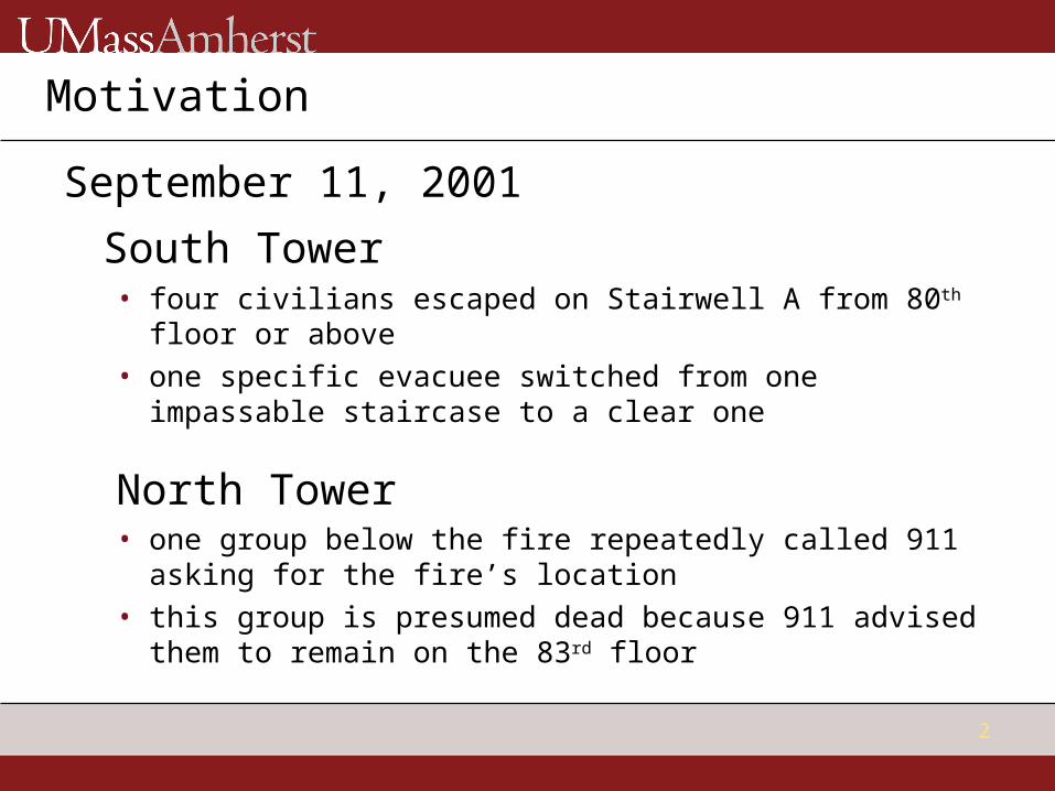
September 11, 2001
South Tower• four civilians escaped on Stairwell A from 80th floor or
above• one specific evacuee switched from one impassable
staircase to a clear one
North Tower• one group below the fire repeatedly called 911 asking
for the fire’s location• this group is presumed dead because 911 advised them
to remain on the 83rd floor
3
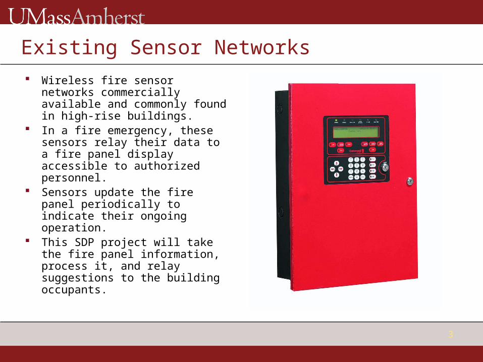
Existing Sensor Networks Wireless fire sensor networks
commercially available and commonly found in high-rise buildings.
In a fire emergency, these sensors relay their data to a fire panel display accessible to authorized personnel.
Sensors update the fire panel periodically to indicate their ongoing operation.
This SDP project will take the fire panel information, process it, and relay suggestions to the building occupants.

4
Fire Control Panel
Routing Algorithm PC
FM Transmitter
Block Diagram
Wireless
Wire
FSM (A/D)
Exit Warning Devices
FM Receiver
Light Displays
Device 1
FSM (A/D)
FM Receiver
Light Displays
Device 2
FM Receiver
Light Displays
Device 3
Digital Logic
Digital Logic
Digital Logic

5
MDR Specifications
Detailed block diagram of routing algorithm design. One wireless transmitter capable of sweeping through four
different frequencies.• Transmitter sweep will consist of sine waves without
modulation.• Transmitter will reach receiver at a distance of at least
10 meters.
One wireless receiver unit attuned only to one particular broadcast frequency.• Receiver will be able to switch its light display off, green,
and red.• Receiver will not respond to frequencies outside of its
pass-band.
Algorithm
1. Flowchart of Algorithm2. Example Scenario3. Algorithm and Transmission

7
Algorithm Light Display Code:
• Red (R) = Heat detected• Green (G) = Clear• Yellow (Y) = Smoke detected
Main Idea of Algorithm: Priority/level of danger from Highest to Lowest:
• Heat/Fire, Smoke, Clear• Red, Yellow, Green
Current floor’s status will be analyzed before, and compared with, the previous floor’s status. The color of light displayed will depend on priority.

8
Algorithm Flowchart
Set floor 1 lights to conditions
sensed
Determine floor 2 (or current floor) lights based on its own conditions and floor 1 (or previous floor) conditions
If 2nd flr has smoke:If 2nd flr is clear: If 2nd flr is on fire:
Is 1st flr on fire?
Is 1st flr on fire?
GreenYellow
N
NY
Y
RedYellow
YN
Red
1st flr have smoke?
Red
9
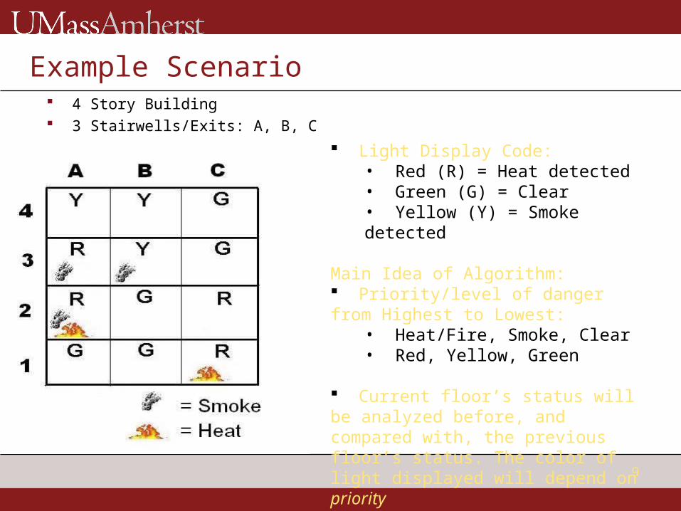
Example Scenario 4 Story Building 3 Stairwells/Exits: A, B, C
Light Display Code:• Red (R) = Heat detected• Green (G) = Clear• Yellow (Y) = Smoke detected
Main Idea of Algorithm: Priority/level of danger from Highest to Lowest:
• Heat/Fire, Smoke, Clear• Red, Yellow, Green
Current floor’s status will be analyzed before, and compared with, the previous floor’s status. The color of light displayed will depend on priority
10
Algorithm and Transmission
Transmission to change light color will occur only if status of sensor has changed from previous check.
Plan: Save matrix of previous sensor data and compare with new matrix to see which have changed.

11
FM Transmitter
What is new from PDR design?• Changed from FSK chip to FM chip.
• FM fits our needs better.• We are transmitting simple data.
• Input will be a sum of sinusoidal waves.• It will transmit different messages at the same fc.• Addition of microcontroller to generate desired message.
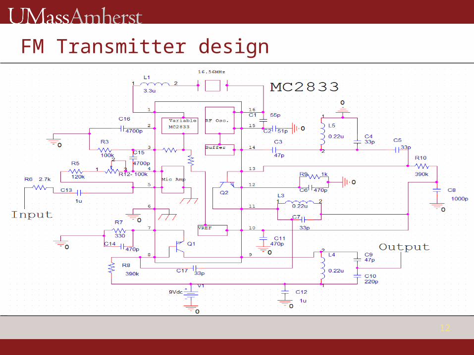
What is the Chip we are using?• The Motorola MC2833 (Low Power FM Transmitter).
• Has an output power in the range of 5dBm to 10dBm. What the design look like?
12
FM Transmitter design

13
FM Transmitter cont’d
What frequency are we planning to use?• We want fc equal to 49.7MHz (US Army range).
Why?• Breadboard has problems to handle VHF.• RLC components are easier to buy.• FM radio stations range is full and has very strong signals. • It is legal to transmit in any FM range as long as we output less than 10dBm (10mW) in power.
What is the problem with the transmitter?• Have the design ready, and all components. However, the Motorola MC2833
Chip has not arrived. What have we done instead?
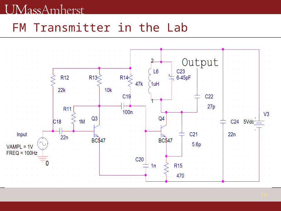
• Concentrated on other parts of project.• Worked on alternative FM transmitter. However, we are currently debugging the
tank component of the design.
14
FM Transmitter in the Lab

15
Receiver Unit What is missing?
• Same problem as transmitter, the Motorola MC3362 Chip has not arrived. We have the receiver design ready, and all components.
Why is it mostly complete then?• The change from FSK to FM also changed the receiver unit.
What is new?• Now the receiver unit is composed of:
• FM receiver• Digital logic:
• BPF, Analog to Digital conversion, CPLD.
• Light display. What is done?
• The Digital logic (BPF, Analog to Digital conversion, CPLD), and the Light display are completed and working.
16
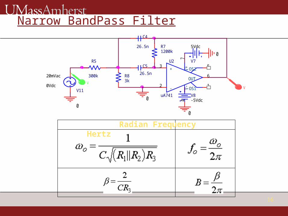
Narrow BandPass Filter
Radian Frequency Hertz
0
R5
300k
V8-5Vdc
R83k
C5
26.5n
R71200k
V
0
U2
uA741
3
2
74
6
1
5+
-
V+
V-
OUT
OS1
OS2
V7
5Vdc
0
0
C4
26.5n
VV11
20mVac
0Vdc
17
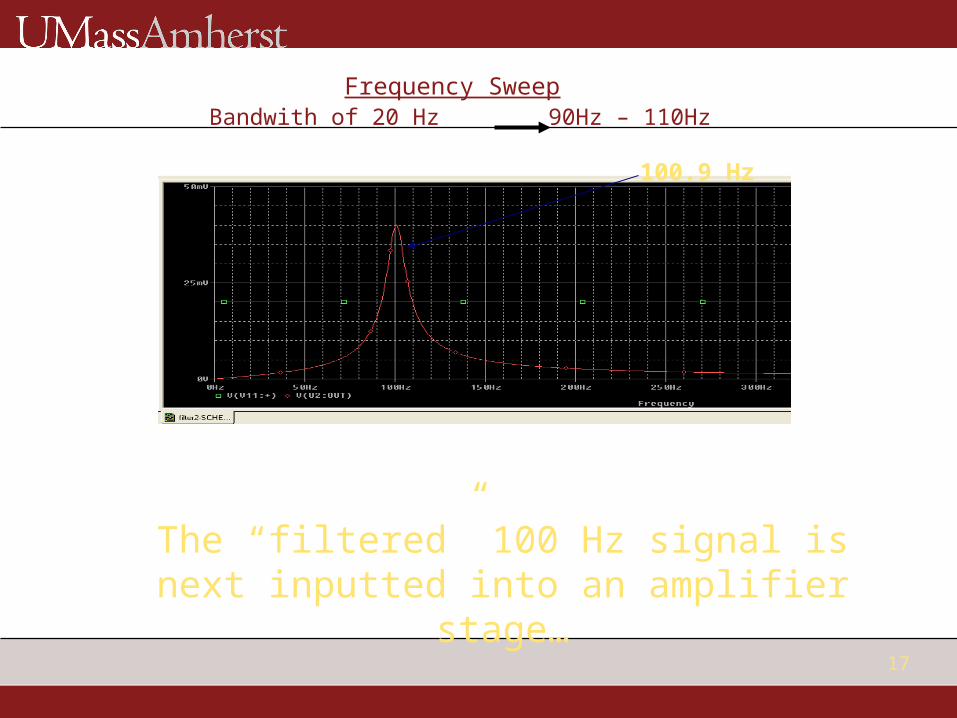
Frequency Sweep Bandwith of 20 Hz 90Hz – 110Hz
100.9 Hz
The “filtered” 100 Hz signal is next inputted into an amplifier stage…

18
Amplifier/Schmitt Trigger

19
Plots of different Stages
20
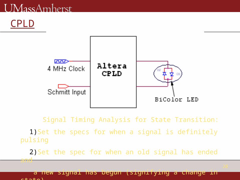
CPLD
Signal Timing Analysis for State Transition:
1)Set the specs for when a signal is definitely pulsing
2)Set the spec for when an old signal has ended and
a new signal has begun (signifying a change in state)

21
Timing Analysis
1) one period of HI’s of shortest period (1/250Hz – 4ms)
2) three cycles worth of LO’s of longest period (1/50 Hz – 20ms) for delay of consectuive transmissions

22
Summary
Routing algorithm logic completed, actual code needs to be written.
Preliminary transmitter and receiver designs completed, awaiting component ICs.
Receiver logic completed, and component LED for light display chosen.
Less than $100 has been spent, and thus the project is well under budget.