1 from design to verilog eecs150 fall2008 - lecture #4 ilia lebedev and chris fletcher fall...
TRANSCRIPT
1
From Design to Verilog
EECS150 Fall2008 - Lecture #4
Ilia Lebedev and Chris Fletcher
Fall 2008 EECS150 - Lec04 - Design in Verilog

2
Administrivia
If you have not yet done so: Create a website login Get on the newsgroup Get a computer account
Webcasts: Working to get the Lecture webcast. Lab Lecture (audio + slides) Missed Lab Lecture 2? Read the slides!
Fall 2008 EECS150 - Lec04 - Design in Verilog

3
Design Problem
Implement a speeding alert system. Approach:
Define the problem Identify available resources Partition the problem Design Interfaces Draw a block diagram Implement blocks using Verilog HDL
Fall 2008 EECS150 - Lec04 - Design in Verilog
4
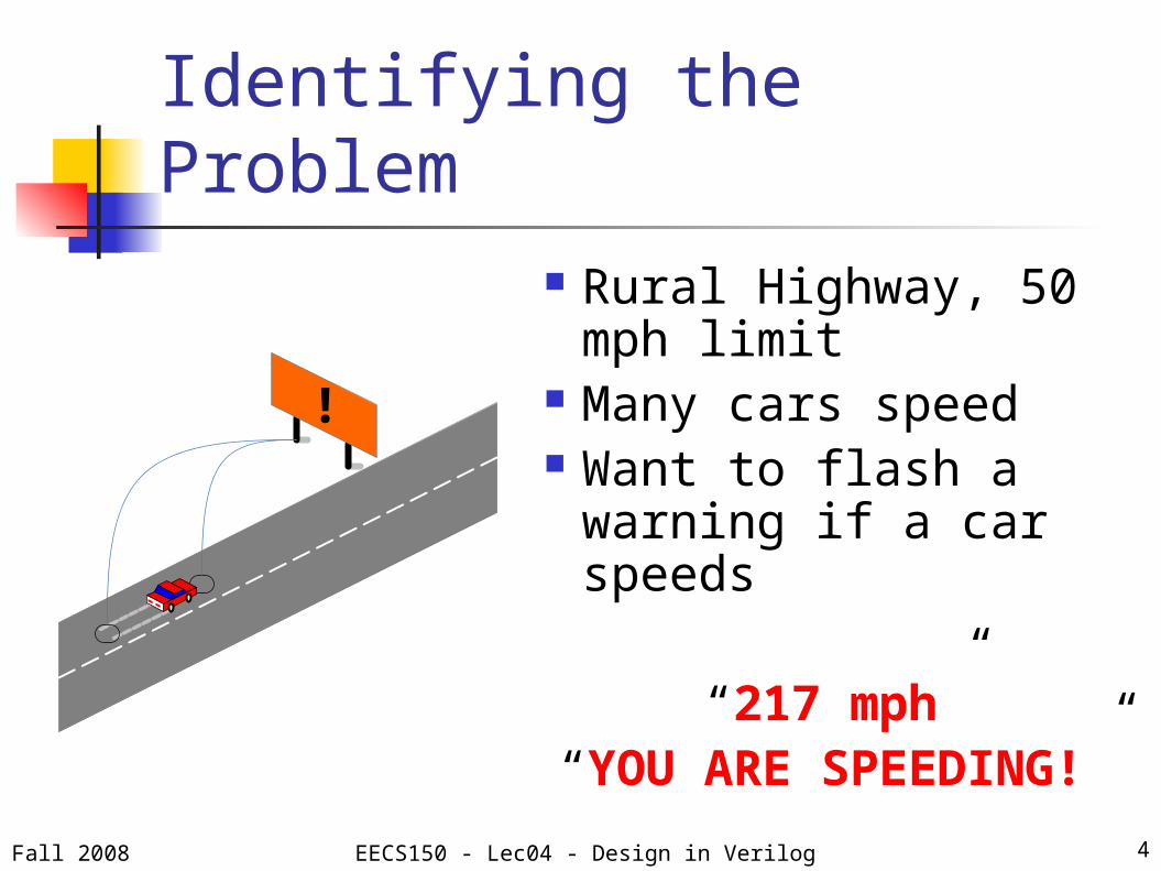
Identifying the Problem Rural Highway, 50 mph
limit Many cars speed Want to flash a
warning if a car speeds
“217 mph”“YOU ARE SPEEDING!”
!
Fall 2008 EECS150 - Lec04 - Design in Verilog

5
Identifying the Resources
Examine what we have to work with:
Two car sensors buried under the road
Warning sign with simple interface An FPGA A 1 MHz clock
We need to design the glue logicFall 2008 EECS150 - Lec04 - Design in Verilog

6
Car Sensor (1) Coiled wire buried
in the pavement Passing car
changes inductance, which is detected by the sensor Logic “1” when the
car is close Logic “0” otherwise
Magic
This part is under the road.
Fall 2008 EECS150 - Lec04 - Design in Verilog

7
Car Sensor (2)
We have two coils Coils are 16 ft. apart
Measure time from sensor 1 to sensor 2,
Use math to calculate speed
16 ft
Fall 2008 EECS150 - Lec04 - Design in Verilog

8
Warning Sign
The sign is self-contained Exposes the following interface:
Inputs: 32-bit sensor reading. ‘Flash' Strobe
Outputs: (what the driver sees)
71 mph
YOU ARE SPEEDING
Sign Controller
Flash -- 32
Time for 16 ft.
Fall 2008 EECS150 - Lec04 - Design in Verilog
9
Interface-Driven Design Design should partition naturally Small pieces better than giant mess! Interface = contract between
partitions
Design good interfaces Hides unnecessary details Makes your circuits reusable Makes your design simpler
Fall 2008 EECS150 - Lec04 - Design in Verilog

10
Interface for Car Sensor (1) Want : Detect car entering, and leaving
Define the interface you want Don’t want : Interpret sensor reading
Abstract details away
What about cars longer than 16ft? Must work for these too
Don't need to worry about cars < 16ft apart
Fall 2008 EECS150 - Lec04 - Design in Verilog

11
Interface for Car Sensor (2)
Detecting a car entering (Start) Sensor 1 on, sensor 2 off
Detecting a car leaving (Stop) Sensor 2 on, Sensor 1 : don’t care
We should know this:
Stop
StartSensor 1
Sensor 2
Fall 2008 EECS150 - Lec04 - Design in Verilog

12
Interface to Measure Time (1)
16 ft in <0.2 seconds speeding What is time in our system?
We have a 1MHz clock Each cycle is 1 μsecond < 200,000 cycles speeding
How do we count the cycles?
Fall 2008 EECS150 - Lec04 - Design in Verilog

13
Interface to Measure Time (1)
Count clock cycles using a Counter Every cycle, we increment 'count' by
1 Also, we can
Reset the counter to 0 Pause the counter
This should look very familiar (HW2):
1+
/32
/32
D Q
C ERCount
/32
/32
Reset
Clock
Enable
Fall 2008 EECS150 - Lec04 - Design in Verilog

14
Designing Control Logic (1)
Have everything except control Control orchestrates the system Control needs to
Read at sensor inputs Manage the counter Talk to the sign occasionally
Fall 2008 EECS150 - Lec04 - Design in Verilog

15
Designing Control Logic (2)
Algorithm for our control:
Whenever a car enters count cycles until car leaves
If # of cycles exceeds threshold, signal the sign.
Otherwise do nothing
Fall 2008 EECS150 - Lec04 - Design in Verilog

16
Finite State Machine (1) Algorithm maps well to FSM paradigm
FSM = Finite State Machine More over next few lectures
We only use Moore Machines Output depends on state only Next state depends on state and inputs
and only
D Q
C
Next State
Input
Output Output
Fall 2008 EECS150 - Lec04 - Design in Verilog

17
Finite State Machine (2)
Our Algorithm Whenever a car
enters count cycles until
car leaves If # of cycles
exceeds threshold, signal the sign
Otherwise do nothing
Stop &(Count > Threshold)
Start
!Stop
Stop & (Count <= Threshold)
Idle[Reset]
Counting[Enable]
Flash[Flash,
TimeOutput]
Fall 2008 EECS150 - Lec04 - Design in Verilog

18
Ready to Implement We now have the high-level design Always draw a block diagram!
Sensor Interface
CL
S1S2
16 ft
Sensor 1
Sensor 2
start
stop
Reset Enable Count
Clock
Clock Counter
FSM Sign
TimeOut/
32
Enable
Fall 2008 EECS150 - Lec04 - Design in Verilog

19
Verilog HDL Go and read the Verilog PDFs!
Verilog is a tool, not what CS150 is about
Learn it quickly, don't go into detail Textual representation of block diagram
Looks like C, but NOT A PROGRAM CS150 is not about software Everything happens concurrently
Fall 2008 EECS150 - Lec04 - Design in Verilog

20
Verilog Modules
vocabulary: “module” “input”,
“output”
module SensorInterface (input wire s1, input wire s2,
output wire start, output wire stop
);
/* Logic */
endmodule
Sensor_Interfacesensor1
sensor2 stop
start
Fall 2008 EECS150 - Lec04 - Design in Verilog

21
Verilog Assign Statements
AB
X
Y1'b0
assign X =
A | ~B;
assign Y = 1’b0;
vocabulary: “assign” “wire” “1’b0” = “1-bit wide wire with a binary representation of
0” assign statements make combinational logic only.
Fall 2008 EECS150 - Lec04 - Design in Verilog

22
Sensor Interface in Verilogmodule SensorInterface (
input wire s1, input wire s2,
output wire start, output wire stop
);
assign start = s1&~s2;assign stop = s2;
endmodule
Sensor_Interfacesensor1
sensor2 stop
start
Fall 2008 EECS150 - Lec04 - Design in Verilog
23
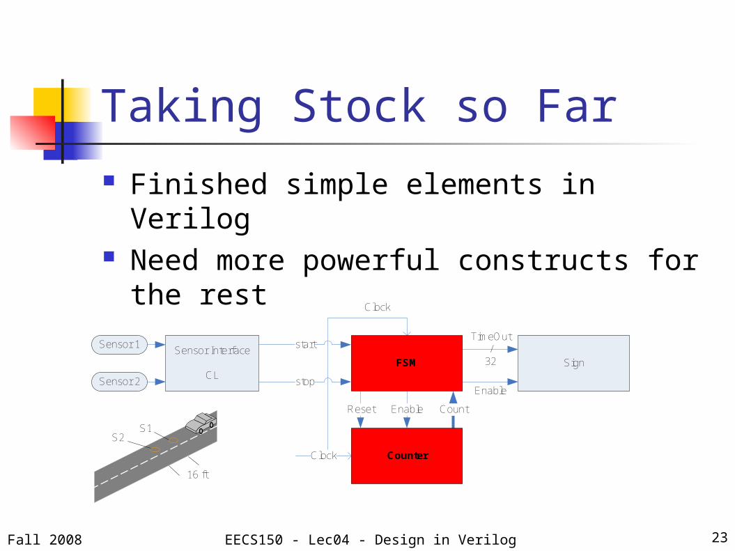
Taking Stock so Far Finished simple elements in Verilog Need more powerful constructs for the
rest
Sensor Interface
CL
S1S2
16 ft
Sensor 1
Sensor 2
start
stop
Reset Enable Count
Clock
Clock Counter
FSM Sign
TimeOut/
32
Enable
Fall 2008 EECS150 - Lec04 - Design in Verilog

always@ Blocks
Describe… When How And under what conditions… to update multiple circuit elements
Behavioral Verilog: Less code always@ blocks come in 2 flavors
Fall 2008 EECS150 - Lec04 - Design in Verilog 24

always@(posedge Clock)
Sequential logic: registers <= (non-blocking) assignments
only Assign each reg at most 1
time/block
Fall 2008 EECS150 - Lec04 - Design in Verilog 25
always@(posedge Clock) begin… your registers here …
end

Counter (1)
Block Diagram … to Verilog
Fall 2008 EECS150 - Lec04 - Design in Verilog 26
module Counter( input wire Clock, input wire Reset, input wire Enable, output reg [31:0] Count )
… Counter code here …
endmodule

Counter (2)
always@(posedge Clock) block
Fall 2008 EECS150 - Lec04 - Design in Verilog 27
always @ (posedge Clock) begin if (Reset) Count <= 32'h0; else Count <= Count + 32'h1; end
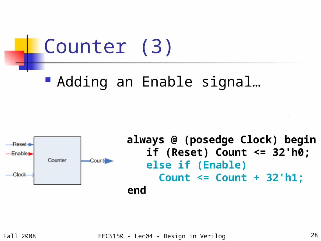
Counter (3)
Adding an Enable signal…
Fall 2008 EECS150 - Lec04 - Design in Verilog 28
always @ (posedge Clock) begin if (Reset) Count <= 32'h0; else if (Enable) Count <= Count + 32'h1; end

The TrafficFSM (revisited)
Looking back at our diagrams…
Fall 2008 EECS150 - Lec04 - Design in Verilog 29
D Q
C
Next State
Input
Output Output

The TrafficFSM in Verilog
Steps Module wrapper State encoding Storing the current state (CS) State transitions Output
Fall 2008 EECS150 - Lec04 - Design in Verilog 30

Module Wrapper (1)
Define name, inputs and outputs
Fall 2008 EECS150 - Lec04 - Design in Verilog 31
module TrafficFSM(input wire Clock,input wire Start, // also serves as Resetinput wire Stop,input wire [31:0] Count,
output wire Reset, // Reset to the Counteroutput wire Enable,output wire Flash,output reg [31:0] TimeOutput);
… the module …endmodule

State Encoding (1)
Tell Verilog about your states Use localparam
Human/Machine readable Local scope
Cannot be overridden!
Fall 2008 EECS150 - Lec04 - Design in Verilog 32
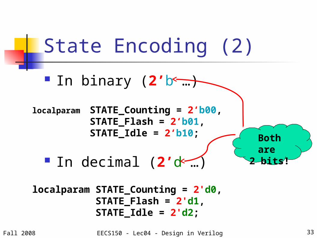
State Encoding (2)
In binary (2’b …)
In decimal (2’d …)
Fall 2008 EECS150 - Lec04 - Design in Verilog 33
localparam STATE_Counting = 2'd0, STATE_Flash = 2'd1, STATE_Idle = 2'd2;
localparam STATE_Counting = 2‘b00,STATE_Flash = 2‘b01,STATE_Idle = 2‘b10; Both are
2 bits!
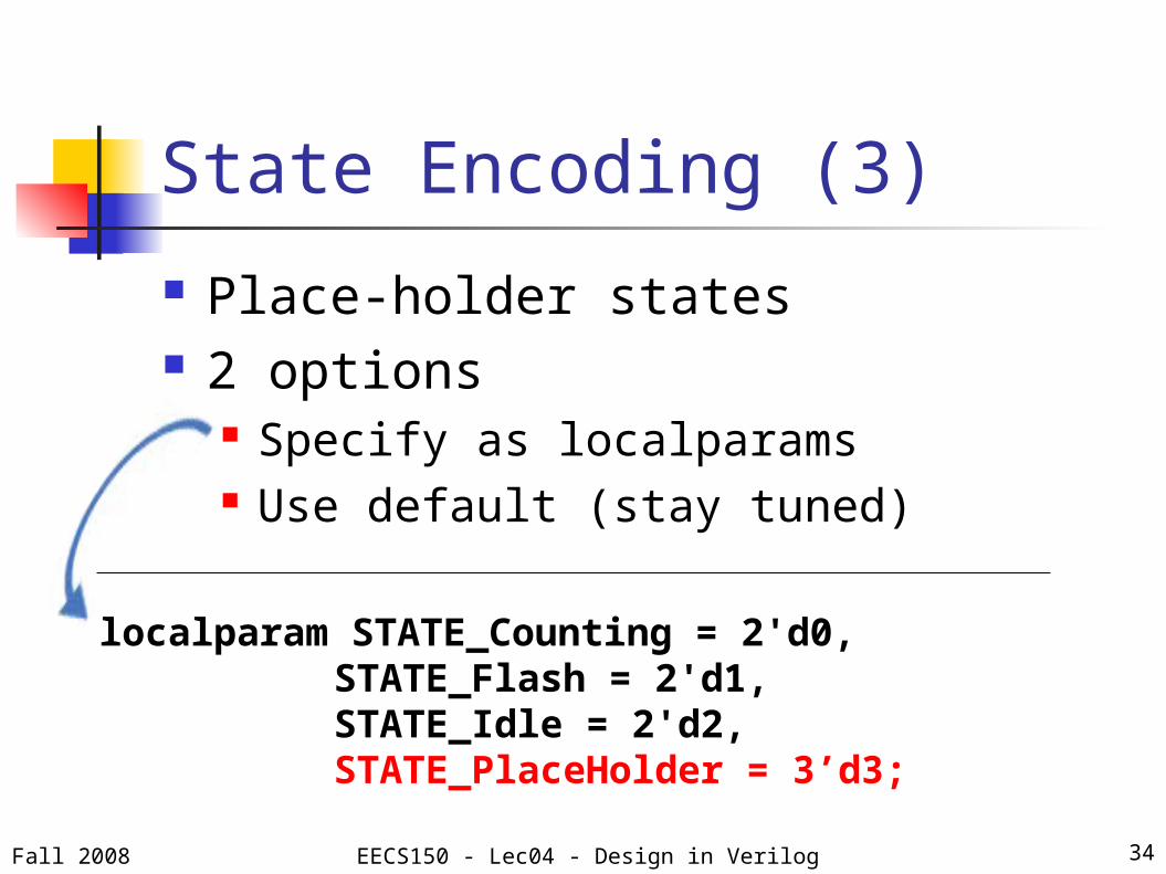
State Encoding (3)
Place-holder states 2 options
Specify as localparams Use default (stay tuned)
Fall 2008 EECS150 - Lec04 - Design in Verilog 34
localparam STATE_Counting = 2'd0, STATE_Flash = 2'd1, STATE_Idle = 2'd2, STATE_PlaceHolder = 3’d3;

State Encoding (4)
One last step! Specify other localparams
The Counter threshold Use ’d
Fall 2008 EECS150 - Lec04 - Design in Verilog 35
localparam THRESHOLD = 32’d200000;

Storing CS (1)
Store state as a reg reg width = width of state localparams
Fall 2008 EECS150 - Lec04 - Design in Verilog 36
reg [1:0] CS;localparam STATE_Counting = 2'd0, STATE_Flash = 2'd1, STATE_Idle = 2'd2;
D Q
C
Next State
Input
Output Output

State Transitions (1)
Steps 1: Store the next state (NS) 2: Specify transition at the Clock-
edge 3: State transition arcs
Fall 2008 EECS150 - Lec04 - Design in Verilog 37
D Q
C
Next State
Input
Output Output1
23
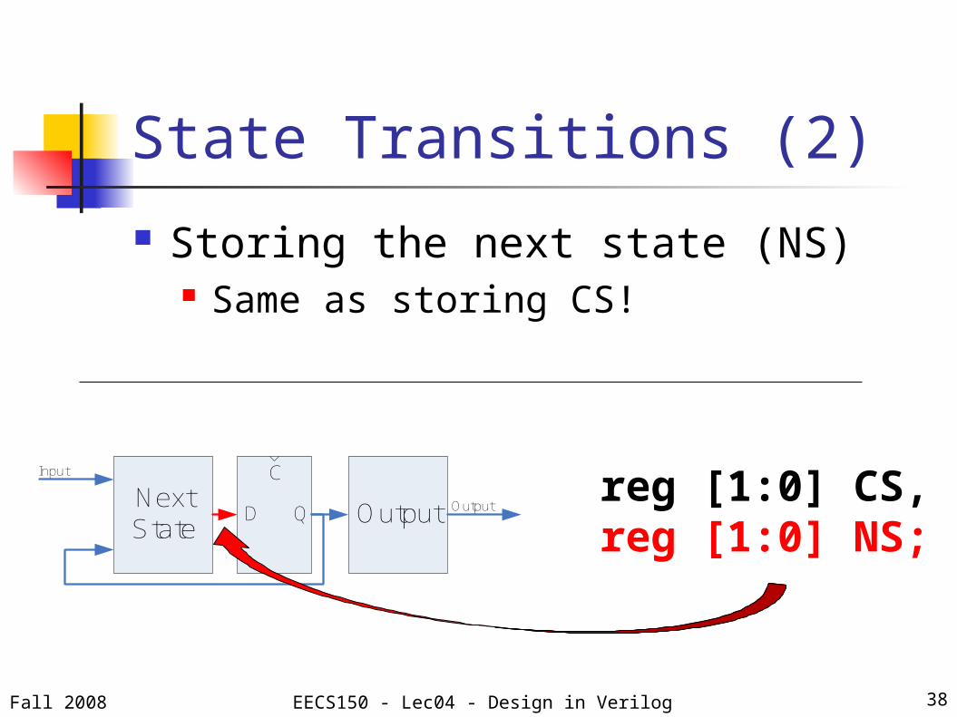
State Transitions (2)
Storing the next state (NS) Same as storing CS!
Fall 2008 EECS150 - Lec04 - Design in Verilog 38
reg [1:0] CS, reg [1:0] NS;
D Q
C
Next State
Input
Output Output

State Transitions (3)
Specify transitions at the Clock-edge State registers (CS) get NS Inferred always@(posedge Clock)
Same for every FSM!
Fall 2008 EECS150 - Lec04 - Design in Verilog 39
always@(posedge Clock) begin if (Start) CS <= STATE_Counting; else CS <= NS;end
D Q
CNext State
Input
Output Output
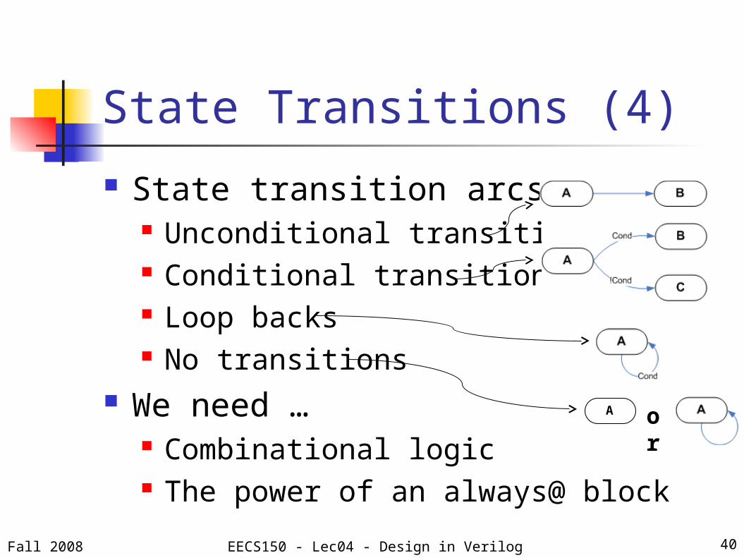
State Transitions (4)
State transition arcs Unconditional transitions Conditional transitions Loop backs No transitions
We need … Combinational logic The power of an always@ block
Fall 2008 EECS150 - Lec04 - Design in Verilog 40
orA

always@( * )
Combinational logic: gates = (blocking) assignments only Assign each reg at least 1 time Stick to ( * ) not (A or B or …)
Fall 2008 EECS150 - Lec04 - Design in Verilog 41
always@( * ) begin … your combinational logic here …end

State Transitions (5)
always@( * ) block structure:
Fall 2008 EECS150 - Lec04 - Design in Verilog 42
always@( * ) begin NS = CS; casex (CS) … 1 case for each state … default : begin NS = 2’bxx; end endcaseend
If we didn’t specify place-holder
states…
If we didn’t specify place-holder
states…

The casex
State Transitions (6)
Fall 2008 EECS150 - Lec04 - Design in Verilog 43
STATE_Counting : begin if (Stop & (Count <= THRESHOLD)) NS = STATE_Flash; else if (Stop & (Count > THRESHOLD)) NS = STATE_Idle;endSTATE_Flash : begin NS = STATE_Idle;endSTATE_Idle : beginend

State Transitions (7)
Specify missing states: 2 options
Place-holders default
+ +
Fall 2008 EECS150 - Lec04 - Design in Verilog 44
case statementcase statement casex statementcasex statement
STATE_PlaceHolder: begin NS = STATE_Counting;end…one case/place-holder state
default : begin NS = 2’bxx;end

Outputs (1)
Outputs can be… 1-bit Multi-bit
Output during… 1 state Multiple states Based on CS
Fall 2008 EECS150 - Lec04 - Design in Verilog 45
D Q
C
Next State
Input
Output Output
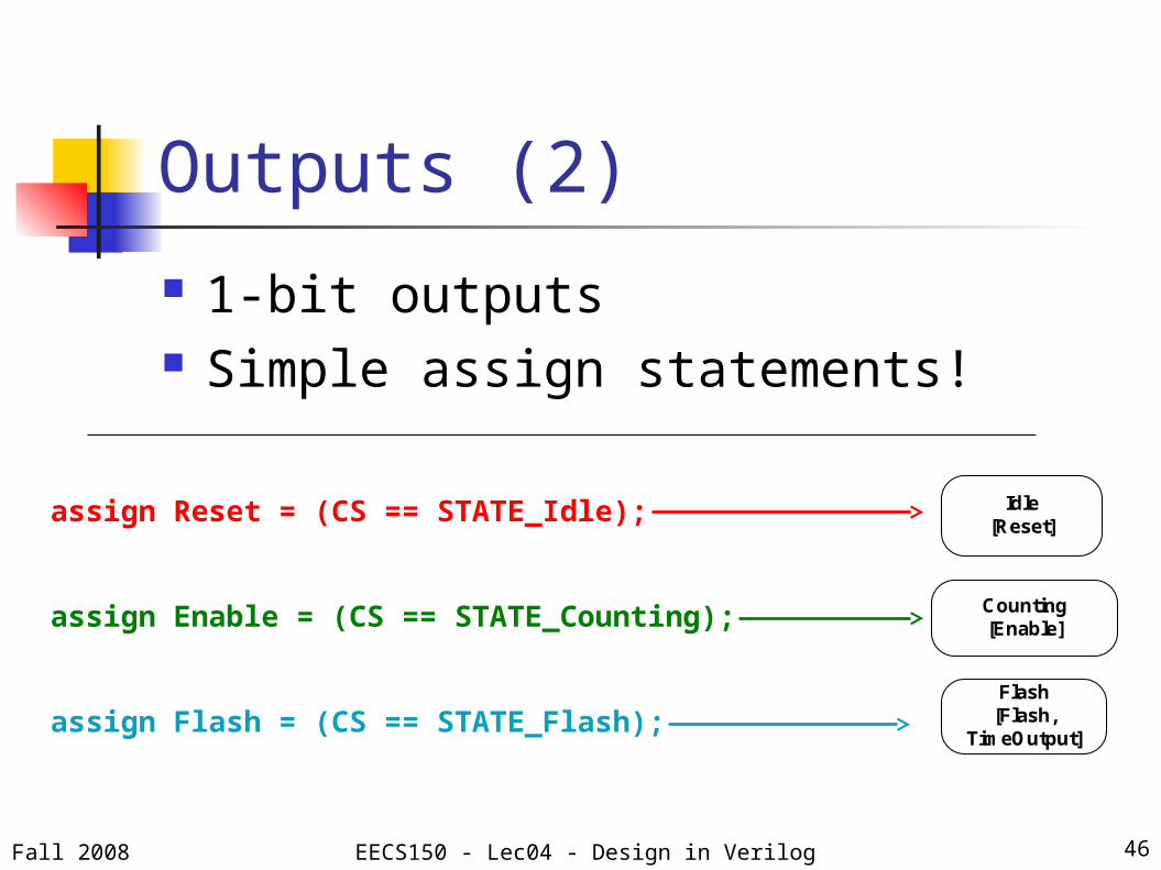
Outputs (2)
1-bit outputs Simple assign statements!
Fall 2008 EECS150 - Lec04 - Design in Verilog 46
assign Reset = (CS == STATE_Idle);
assign Enable = (CS == STATE_Counting);
assign Flash = (CS == STATE_Flash);Flash
[Flash, TimeOutput]
Counting[Enable]
Idle[Reset]

Outputs (3)
Multi-bit outputs Inferred always@( * ) block
Fall 2008 EECS150 - Lec04 - Design in Verilog 47
always@( * ) beginTimeOutput = 32'b0;case (CS)
STATE_Flash : begin TimeOutput = Count;end
endcaseend
Flash[Flash,
TimeOutput]
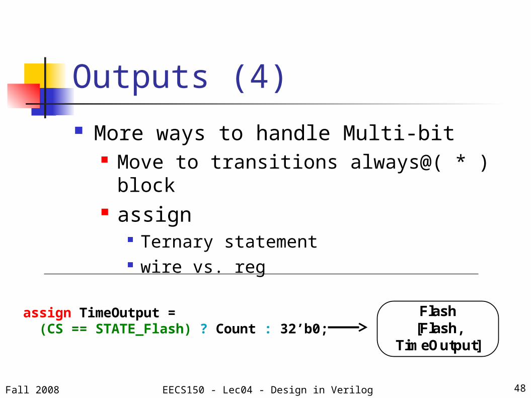
Outputs (4) More ways to handle Multi-bit
Move to transitions always@( * ) block assign
Ternary statement wire vs. reg
Fall 2008 EECS150 - Lec04 - Design in Verilog 48
assign TimeOutput = (CS == STATE_Flash) ? Count : 32’b0;
Flash[Flash,
TimeOutput]

The Complete Design
Code is posted on the website Slides are posted on the website
Run through Simulation & Synthesis
Fall 2008 EECS150 - Lec04 - Design in Verilog 49