1 hvacr214 – electrical for oil series and parallel circuits
TRANSCRIPT
1
HVACR214 – Electrical for OilHVACR214 – Electrical for Oil
Series and Parallel CircuitsSeries and Parallel Circuits

2
IntroductionIntroduction
• So far we have looked at circuits that have one path for electricity to go as well as a single switching device.
• The majority of circuits you work in with HVAC will be more complex
• Therefore we must understand the two ways circuits are designed.
• So far we have looked at circuits that have one path for electricity to go as well as a single switching device.
• The majority of circuits you work in with HVAC will be more complex
• Therefore we must understand the two ways circuits are designed.
3
Ohms LawOhms Law
• Ohms law defines the relationship between Voltage (E), current (I), and resistance (R).
• The formula is:
E = I * R
• Ohms law defines the relationship between Voltage (E), current (I), and resistance (R).
• The formula is:
E = I * R

4
Ohms LawOhms Law
• Using the formula: E = I x R and having 1 amp of current, with 1 ohm of resistance there will be 1 Volt.
• E = 1 x 1 = 1
• Using the same formula with .5 amps and 100 ohms you will measure 50 Volts.
• Using the formula: E = I x R and having 1 amp of current, with 1 ohm of resistance there will be 1 Volt.
• E = 1 x 1 = 1
• Using the same formula with .5 amps and 100 ohms you will measure 50 Volts.
5
Ohms LawOhms Law
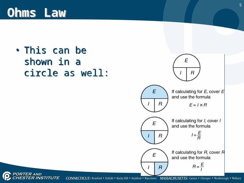
• This can be shown in a circle as well:
• This can be shown in a circle as well:
6
Series CircuitsSeries Circuits
• Series circuits exist when:– The flow of electrons (current) must pass through a
series of components.– Switches that control loads are wired in series with
these loads.
• Series circuits exist when:– The flow of electrons (current) must pass through a
series of components.– Switches that control loads are wired in series with
these loads.
7
Series CircuitsSeries Circuits
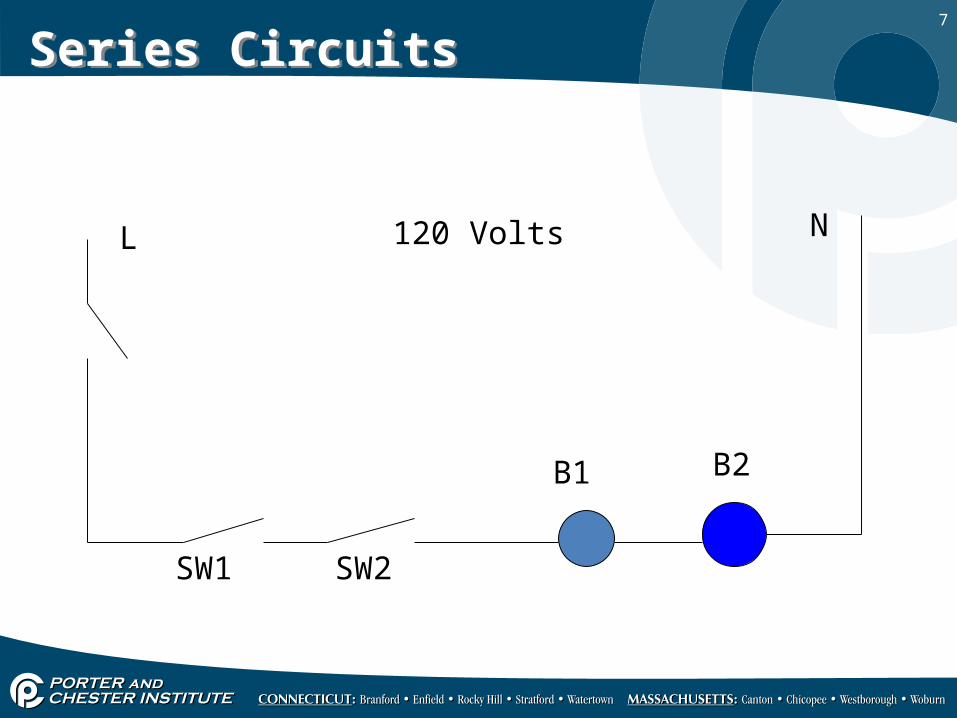
L N
SW1 SW2
B1 B2
120 Volts
8
Series CircuitsSeries Circuits
• SW1 is in series with SW2 which is in series with B1 and B2
• If any one of of the components in this circuit is open of fails the remainder of the circuit will not work.
• Loads in series split the source voltage based on their resistance. Neither B1 or B2 will be getting full source voltage.
• SW1 is in series with SW2 which is in series with B1 and B2
• If any one of of the components in this circuit is open of fails the remainder of the circuit will not work.
• Loads in series split the source voltage based on their resistance. Neither B1 or B2 will be getting full source voltage.

9
Series CircuitsSeries Circuits
• The amperage is the same through the entire circuit.
• The total resistance is the sum of all the individual components resistance.
• The voltage drop (or voltage measured) across each load can be calculated using ohms law for that individual load.
• The amperage is the same through the entire circuit.
• The total resistance is the sum of all the individual components resistance.
• The voltage drop (or voltage measured) across each load can be calculated using ohms law for that individual load.

10
Series CircuitsSeries Circuits
• In the HVAC industry it is rare to see loads in series.
• It is frequent to see switches in series.• Both switches must be closed to provide a path for
electricity. • In a series circuit any open will cause the circuit
not to work.
• In the HVAC industry it is rare to see loads in series.
• It is frequent to see switches in series.• Both switches must be closed to provide a path for
electricity. • In a series circuit any open will cause the circuit
not to work.
11
Troubleshooting Series CircuitsTroubleshooting Series Circuits
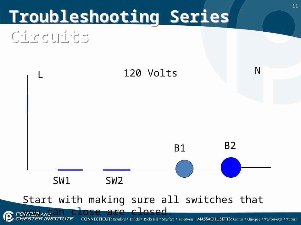
L N
SW1 SW2
B1 B2
120 Volts
Start with making sure all switches that you can close are closed.

12
Troubleshooting Series CircuitsTroubleshooting Series Circuits
L N
SW1 SW2
B1 B2
120 Volts
Now check voltage across the source.
120 V

13
Troubleshooting Series CircuitsTroubleshooting Series Circuits
L N
SW1 SW2
B1 B2
120 Volts
Now check voltage across the first switch (Service Switch)
0 V

14
Troubleshooting Series CircuitsTroubleshooting Series Circuits
L N
SW1 SW2
B1 B2
120 Volts
Now check voltage Source to Line side of SW1
0 V

15
Troubleshooting Series CircuitsTroubleshooting Series Circuits
L N
SW1 SW2
B1 B2
120 Volts
Now check voltage Source to Load side of SW1
0 V

16
Troubleshooting Series CircuitsTroubleshooting Series Circuits
L N
SW1 SW2
B1 B2
120 Volts
Now check voltage Source to Line side of SW2
0 V
17
Troubleshooting Series CircuitsTroubleshooting Series Circuits
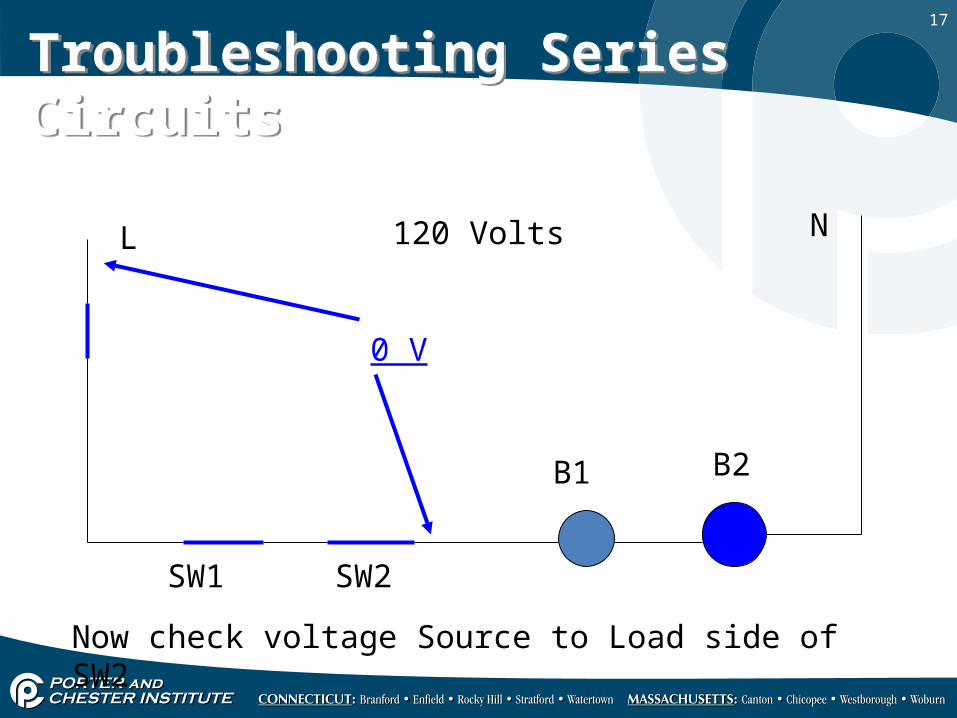
L N
SW1 SW2
B1 B2
120 Volts
Now check voltage Source to Load side of SW2
0 V
18
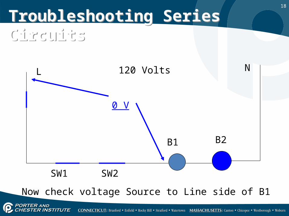
Troubleshooting Series CircuitsTroubleshooting Series Circuits
L N
SW1 SW2
B1 B2
120 Volts
Now check voltage Source to Line side of B1
0 V

19
Troubleshooting Series CircuitsTroubleshooting Series Circuits
L N
SW1 SW2
B1 B2
120 Volts
Now check voltage Source to Neutral side of B1
60 V

20
Troubleshooting Series CircuitsTroubleshooting Series Circuits
L N
SW1 SW2
B1 B2
120 Volts
Now check voltage Source to Line side of B2
60 V
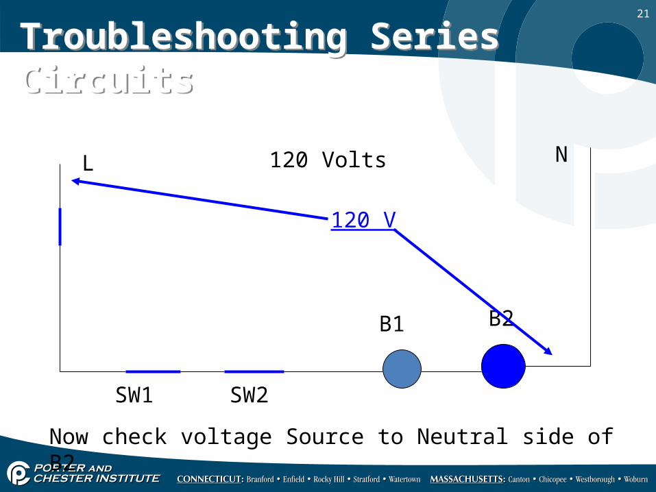
21
Troubleshooting Series CircuitsTroubleshooting Series Circuits
L N
SW1 SW2
B1 B2
120 Volts
Now check voltage Source to Neutral side of B2
120 V
22
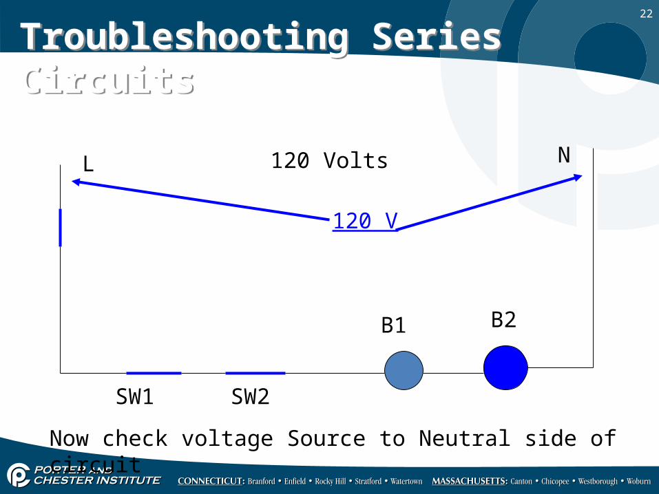
Troubleshooting Series CircuitsTroubleshooting Series Circuits
L N
SW1 SW2
B1 B2
120 Volts
Now check voltage Source to Neutral side of circuit
120 V

23
Troubleshooting Series CircuitsTroubleshooting Series Circuits
• When troubleshooting a series circuit if you get source voltage across any switching device that switch is open.
• When troubleshooting a series circuit if you get source voltage across a load and that load is not operating the load is bad.
• When troubleshooting a series circuit if you get source voltage across any switching device that switch is open.
• When troubleshooting a series circuit if you get source voltage across a load and that load is not operating the load is bad.
24
Parallel CircuitsParallel Circuits
• Parallel circuits are the most common circuit in the HVAC industry for loads.
• These are the circuits that do the work.• All loads in parallel receive full source potential
(voltage)• Parallel circuits exist when a circuit has more than
one load, but none of the loads receive voltage from another load.
25
Parallel CircuitsParallel Circuits
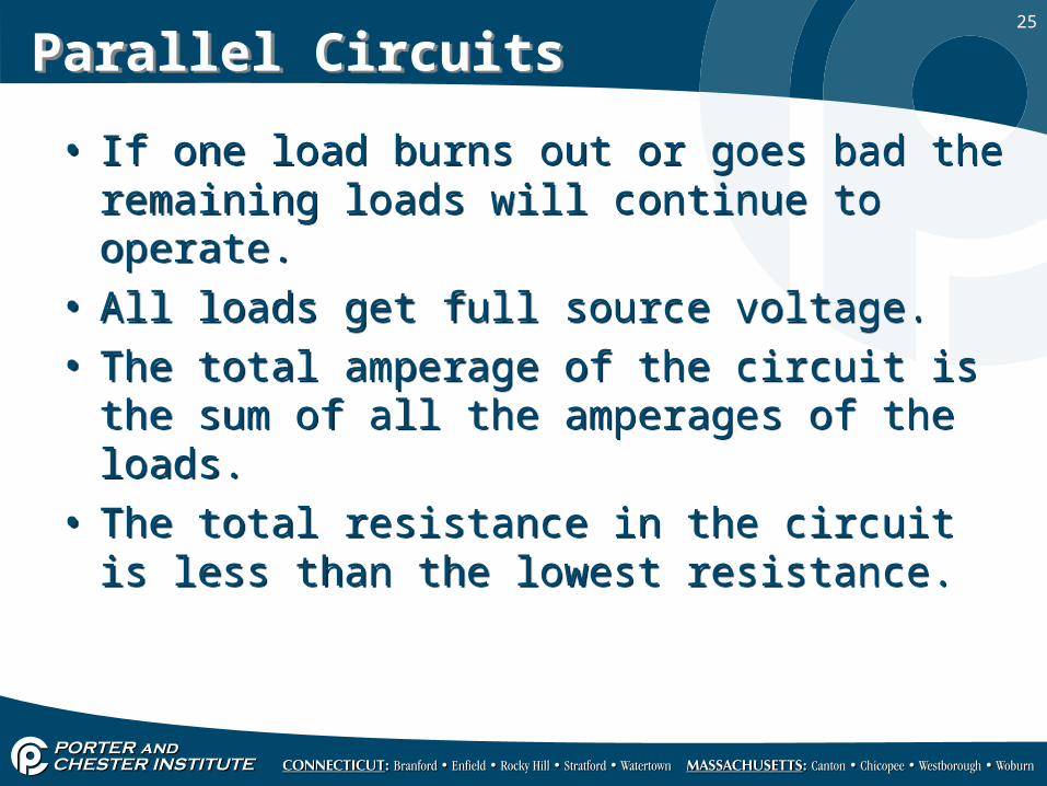
• If one load burns out or goes bad the remaining loads will continue to operate.
• All loads get full source voltage.• The total amperage of the circuit is the sum of all
the amperages of the loads.• The total resistance in the circuit is less than the
lowest resistance.
• If one load burns out or goes bad the remaining loads will continue to operate.
• All loads get full source voltage.• The total amperage of the circuit is the sum of all
the amperages of the loads.• The total resistance in the circuit is less than the
lowest resistance.
26
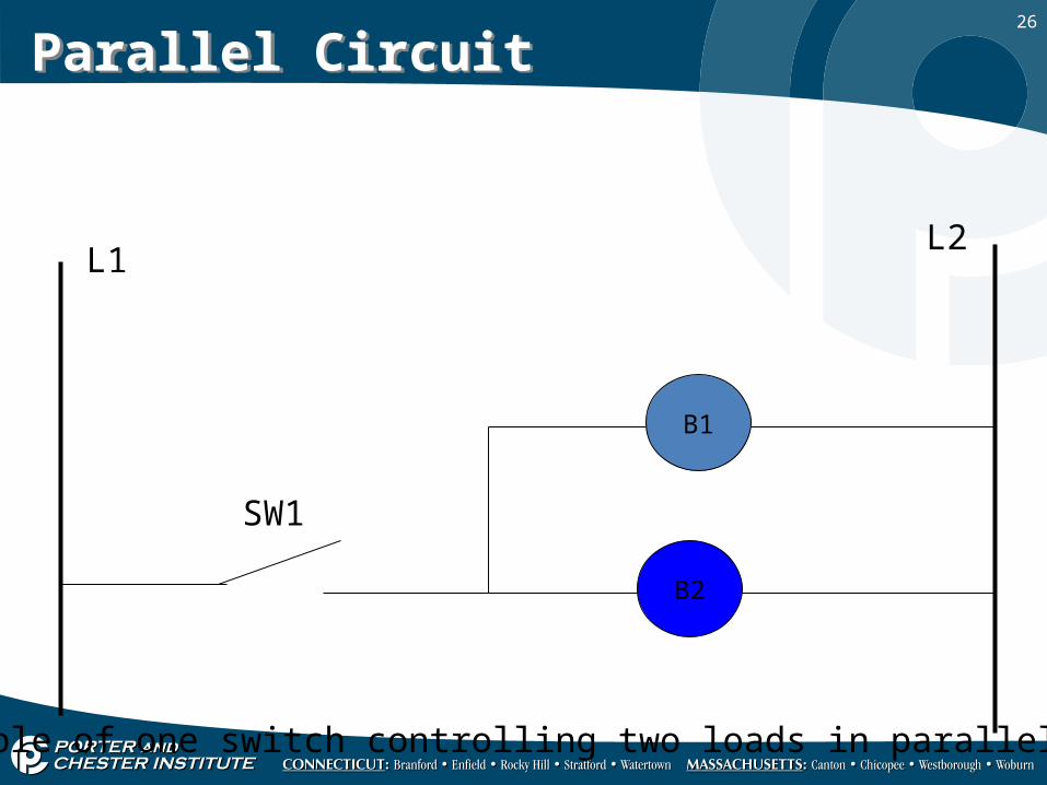
Parallel CircuitParallel Circuit
L1L2
B1
B2
SW1
Example of one switch controlling two loads in parallel.

27
Parallel CircuitParallel Circuit
L1L2
B1
B2
SW1
Example of two loads in parallel each controlled by a switch.
SW2
28
Troubleshooting parallel circuitsTroubleshooting parallel circuits
• The same basic procedure as a series circuit.• Start at the source.
• The same basic procedure as a series circuit.• Start at the source.

29
Parallel CircuitParallel Circuit
L1L2
B1
B2
SW1
First make sure all switches you can control are closed.
SW1
30
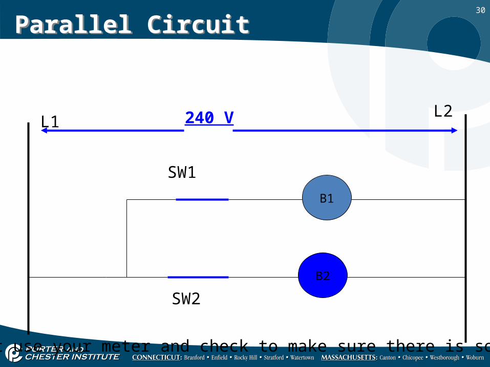
Parallel CircuitParallel Circuit
L1L2
B1
B2
SW1
Next use your meter and check to make sure there is source.
SW2
240 V
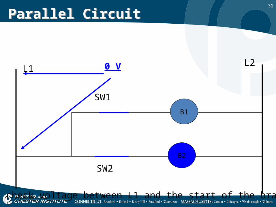
31
Parallel CircuitParallel Circuit
L1L2
B1
B2
SW1
Next check voltage between L1 and the start of the branch.
SW2
0 V
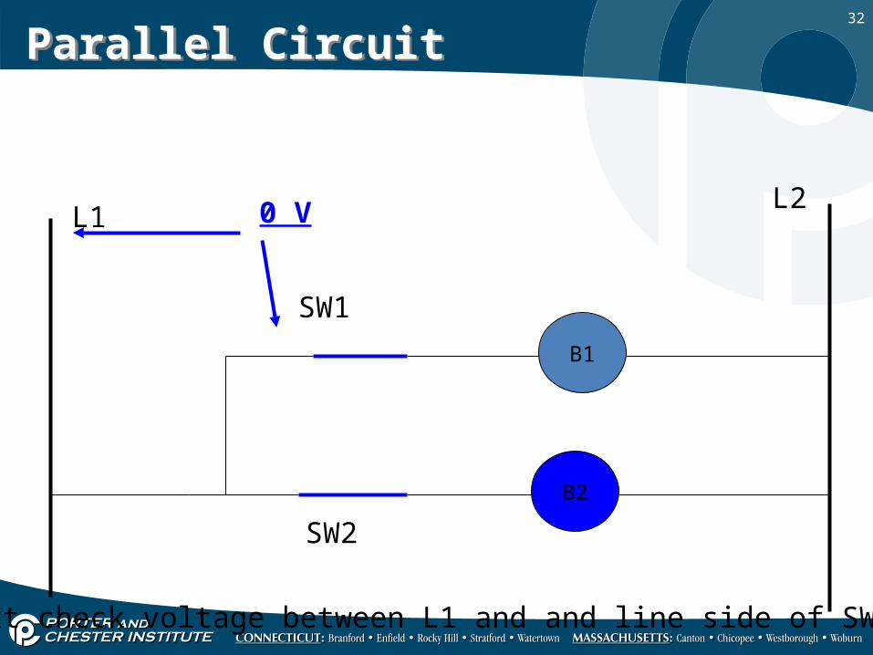
32
Parallel CircuitParallel Circuit
L1L2
B1
B2
SW1
Next check voltage between L1 and and line side of SW1.
SW2
0 V

33
Parallel CircuitParallel Circuit
L1L2
B1
B2
SW1
Next check voltage between L1 and and load side of SW1.
SW2
0 V

34
Parallel CircuitParallel Circuit
L1L2
B1
B2
SW1
Next check voltage between L1 and and line side of B1.
SW2
0 V

35
Parallel CircuitParallel Circuit
L1L2
B1
B2
SW1
Next check voltage between L1 and and load side of B1.
SW2
240 V

36
Parallel CircuitParallel Circuit
L1L2
B1
B2
SW1
Next check voltage between L1 and and then the connection to neutral.
SW2
240 V
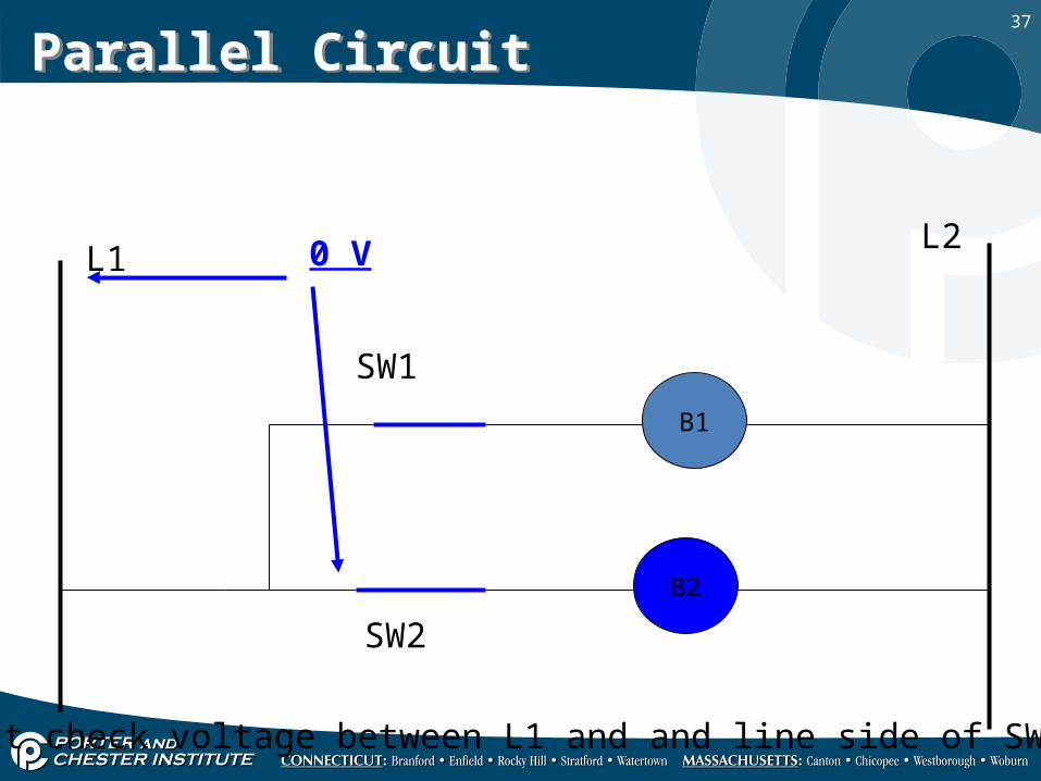
37
Parallel CircuitParallel Circuit
L1L2
B1
B2
SW1
Next check voltage between L1 and and line side of SW2.
SW2
0 V
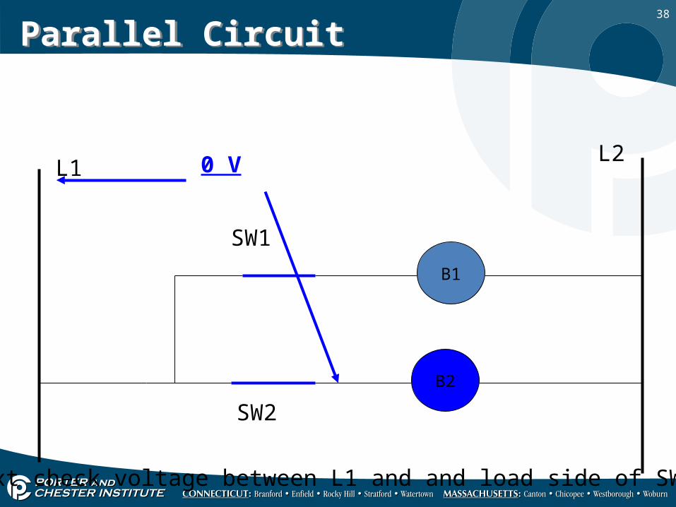
38
Parallel CircuitParallel Circuit
L1L2
B1
B2
SW1
Next check voltage between L1 and and load side of SW2.
SW2
0 V
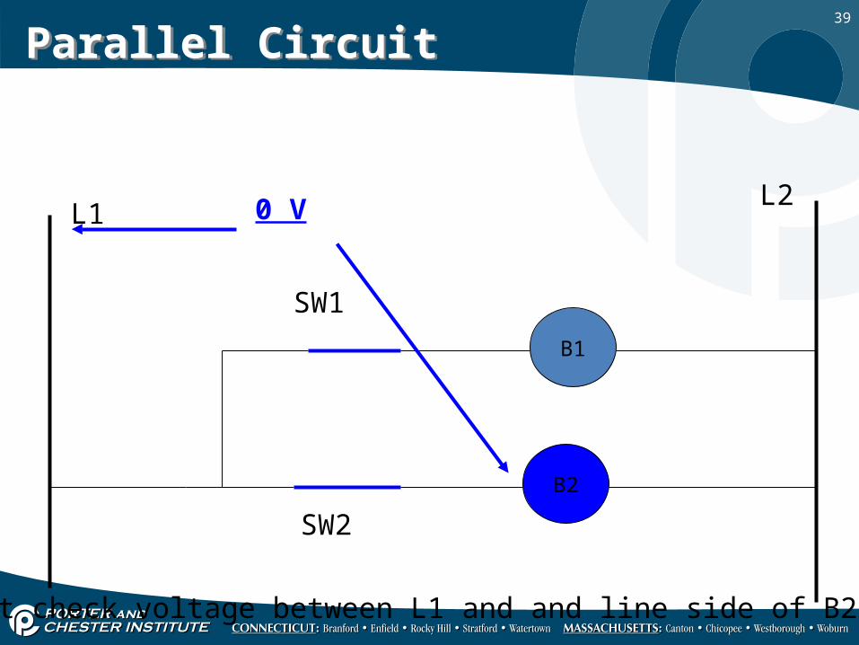
39
Parallel CircuitParallel Circuit
L1L2
B1
B2
SW1
Next check voltage between L1 and and line side of B2.
SW2
0 V
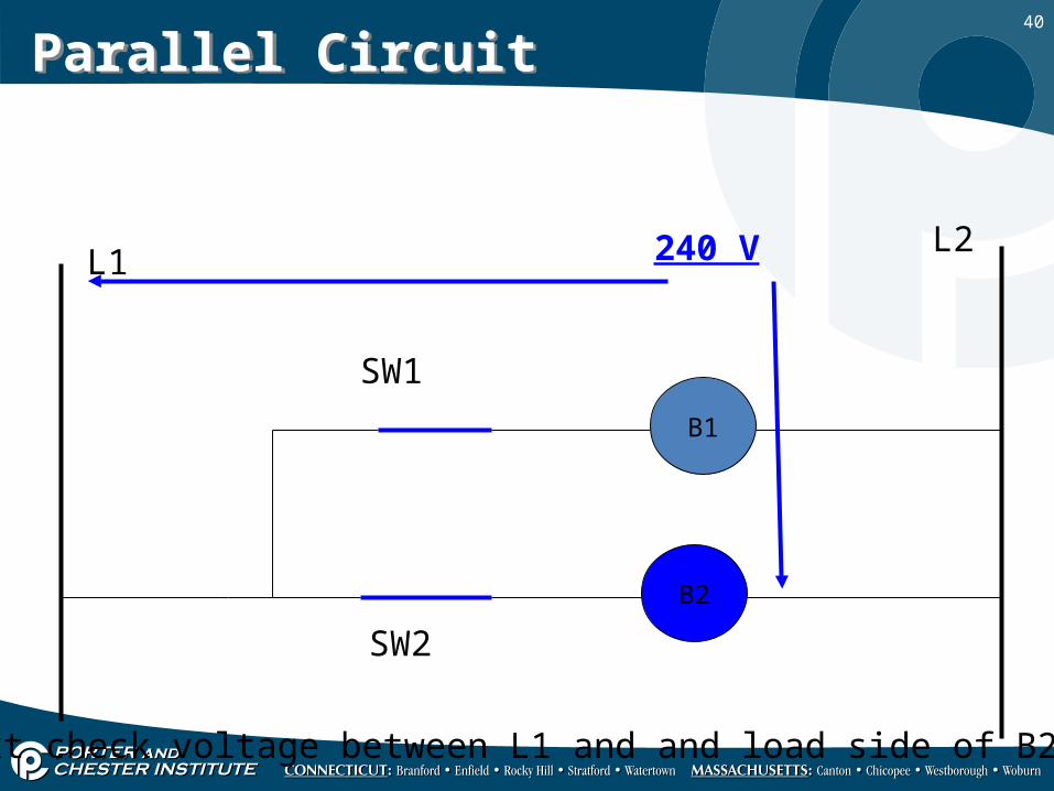
40
Parallel CircuitParallel Circuit
L1L2
B1
B2
SW1
Next check voltage between L1 and and load side of B2.
SW2
240 V

41
Parallel CircuitParallel Circuit
L1L2
B1
B2
SW1
Next check voltage between L1 and and then the connection to neutral.
SW2
240 V
42
Troubleshooting Parallel CircuitsTroubleshooting Parallel Circuits
• When troubleshooting a parallel circuit if you get source voltage across any switching device that switch is open.
• When troubleshooting a parallel circuit if you get source voltage across a load and that load is not operating the load is bad.
• When troubleshooting a parallel circuit if you get source voltage across any switching device that switch is open.
• When troubleshooting a parallel circuit if you get source voltage across a load and that load is not operating the load is bad.
43
Troubleshooting rulesTroubleshooting rules
• Start at source and work your way from there.• If you get any voltage across a switch that switch
is open (or bad).• If you get voltage at a load and the load is not
working it has failed. Replace it.
• Start at source and work your way from there.• If you get any voltage across a switch that switch
is open (or bad).• If you get voltage at a load and the load is not
working it has failed. Replace it.

44
Shop ProjectsShop Projects
• Build and check a series circuit using your meter.• Build and check a parallel circuit using your meter.• Continue until you have completed lab 5.
• Build and check a series circuit using your meter.• Build and check a parallel circuit using your meter.• Continue until you have completed lab 5.

45