1. in the figure shown, the capacity of the condenser c is
TRANSCRIPT

1. In the figure shown, the capacity of the condenser C is F2 . The current in 2 resistor is
[IIT 1982]
(a) 9 A (b) 0.9 A
(c) A9
1 (d) A
9.0
1
6V 2.8
+ –
2F 4
3
2

2. When the key K is pressed at time 0t , which of the following statements about the current
I in the resistor AB of the given circuit is true [CBSE PMT 1995]
(a) I = 2 mA at all t
(b) I oscillates between 1 mA and 2mA
(c) I = 1 mA at all t
(d) At t = 0 , I = 2 mA and with time it goes to 1 mA
B
1000
C 1F
A
K 2V
10
00
3. Two cells of equal e.m.f. and of internal resistances 1r and )( 212 rrr are connected in series.
On connecting this combination to an external resistance R, it is observed that the potential
difference across the first cell becomes zero. The value of R will be
[MP PET 1985; KCET 2005; Kerala PMT 2005]
(a) 21 rr (b) 21 rr
(c) 2
21 rr (d)
2
21 rr

4. When connected across the terminals of a cell, a voltmeter measures 5V and a connected
ammeter measures 10 A of current. A resistance of 2 ohms is connected across the terminals
of the cell. The current flowing through this resistance will be [MP PMT
1997]
(a) 2.5 A (b) 2.0 A
(c) 5.0 A (d) 7.5 A

5. A microammeter has a resistance of 100 and full scale range of A50 . It can be used as a
voltmeter or as a higher range ammeter provided a resistance is added to it. Pick the correct
range and resistance combination
[SCRA 1996; AMU (Med.) 2001; Roorkee 2000]
(a) 50 V range with k10 resistance in series
(b) 10 V range with k200 resistance in series
(c) 10 mA range with 1 resistance in parallel
(d) 10 mA range with 1.0 resistance in parallel

6. In the given circuit, it is observed that the current I is independent of the value of the
resistance R6. Then the resistance values must satisfy [IIT-JEE (Screening) 2001]
(a) 643521 RRRRRR
(b) 65
11
RR
4321
11
RRRR
(c) 3241 RRRR
(d) 654231 RRRRRR
R5
R1
R2
R6 R3
R4
I

7. In the given circuit, with steady current, the potential drop across the capacitor must be [IIT-JEE (Screening) 2001]
(a) V
(b) V / 2
(c) V / 3
(d) 2V / 3
R
2R
C
V
V
2V

8. In the circuit element given here, if the potential at point B, VB = 0, then the potentials of A
and D are given as
[AMU (Med.) 2002]
(a) VVVV DA 2,5.1 (b) VVVV DA 2,5.1
(c) VVVV DA 5.0,5.1 (d) VVVV DA 5.0,5.1
A B C D
1 amp 1.5 2.5 2V

9. The equivalent resistance between the points P and Q in the network given here is equal to
(given 2
3r )
[AMU (Med.) 2002]
(a) 2
1
(b) 1
(c) 2
3
(d) 2
r r
r r
r r
r
r
P Q

10. In the shown arrangement of the experiment of the meter bridge if AC corresponding to null
deflection of galvanometer is x, what would be its value if the radius of the wire AB is
doubled [IIT-JEE (Screening) 2003]
(a) x
(b) x/4
(c) 4x
(d) 2x
B
R1
C
R2
A
G
x

11. The resistance of a wire of iron is 10 ohms and temp. coefficient of resistivity is C /105 3 .
At C20 it carries 30 milliamperes of current. Keeping constant potential difference between
its ends, the temperature of the wire is raised to C120 . The current in milliamperes that
flows in the wire is [MP PMT 1994]
(a) 20 (b) 15
(c) 10 (d) 40
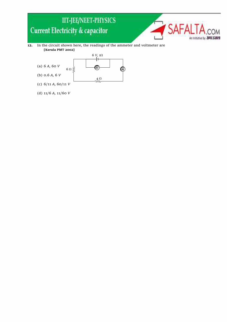
12. In the circuit shown here, the readings of the ammeter and voltmeter are
[Kerala PMT 2002]
(a) 6 A, 60 V
(b) 0.6 A, 6 V
(c) 6/11 A, 60/11 V
(d) 11/6 A, 11/60 V
6 V, 1
4
6 A V

13. Length of a hollow tube is 5m, it’s outer diameter is 10 cm and thickness of it’s wall is 5 mm.
If resistivity of the material of the tube is 1.7 10–8
m then resistance of tube will be
(a) 5.6 10–5
(b) 2 10–5
(c) 4 10–5
(d) None of these

14. Potential difference across the terminals of the battery shown in figure is (r = internal
resistance of battery)
(a) 8 V
(b) 10 V
(c) 6 V
(d) Zero
10 V
4
r =1

15. As the switch S is closed in the circuit shown in figure, current passed through it is
(a) 4.5 A
(b) 6.0 A
(c) 3.0 A
(d) Zero
4 2
B
S
2
5 V
A
20 V

16. In the circuit shown in figure reading of voltmeter is V1 when only S1 is closed, reading of
voltmeter is V2 when only S2 is closed and reading of voltmeter is V3 when both S1 and S2 are
closed. Then
(a) V3 > V2 > V1
(b) V2 > V1 > V3
(c) V3 > V1 > V2
(d) V1 > V2 > V3
R
V
E
6R
3R
S1
S2

17. In the adjoining circuit diagram each resistance is of 10 . The current in the arm AD will be
(a) 5
2i
(b) 5
3i
(c) 5
4 i
(d) 5
i
i
A
D
C
B
E
F i

18. In the circuit of adjoining figure the current through 12 resister will be
(a) 1 A
(b) A5
1
(c) A5
2
(d) 0 A
5 10
5V 5V
12
C A
F E
5

19. The reading of the ideal voltmeter in the adjoining diagram will be
(a) 4 V
(b) 8 V
(c) 12 V
(d) 14 V
V
10V 20
10 4V
C N B
A

20. The resistance of the series combination of two resistance is S. When they are joined in
parallel the total resistance is P. If S = nP, then the minimum possible value of n is
[AIEEE 2004]
(a) 4 (b) 3
(c) 2 (d) 1

21. A moving coil galvanometer has 150 equal divisions. Its current sensitivity is 10 divisions per
milliampere and voltage sensitivity is 2 divisions per millivolt. In order that each division
reads 1 volt, the resistance in ohms needed to be connected in series with the coil will be
[AIEEE 2005]
(a) 99995 (b) 9995
(c) 310 (d) 510

22. Which of the adjoining graphs represents ohmic resistance
[CPMT 1981; DPMT 2002]
(a) (b)
(c) (d)
I
V
I
V
I
V
I
V

23. The voltage V and current I graph for a conductor at two different temperatures 1T and 2T
are shown in the figure. The relation between 1T and 2T is
[MP PET 1996; KCET 2002]
(a) 21 TT
(b) 21 TT
(c) 21 TT
(d) 21 TT
V
I
T1
T2

24. Variation of current and voltage in a conductor has been shown in the diagram below. The
resistance of the conductor is.
(a) 4 ohm (b) 2 ohm
(c) 3 ohm (d) 1 ohm
1 2 3 4 5 6
1
2
3
4
5
6
i
V

25. For a cell, the graph between the potential difference (V) across the terminals of the cell and
the current (I) drawn from the cell is shown in the figure. The e.m.f. and the internal
resistance of the cell are
(a) 5.0,2V (b) 4.0,2V
(c) 5.0,2V (d) 4.0,2V
1 2 3 4 5
2.0
1.5
1.0
0.5
0
V(Volts)
I(amperes)

26. A battery consists of a variable number 'n' of identical cells having internal resistances
connected in series. The terminals of battery are short circuited and the current i is
measured. Which of the graph below shows the relation ship between i and n
(a) (b)
(c) (d)
i
n O n
i
O
i
O n
i
O n

27. In an experiment, a graph was plotted of the potential difference V between the terminals of
a cell against the circuit current i by varying load rheostat. Internal conductance of the cell
is given by
(a) xy (b) x
y
(c) y
x (d) (x – y)
y
x
i
V
V A

28. V-i graphs for parallel and series combination of two identical resistors are as shown in
figure. Which graph represents parallel combination
(a) A (b) B
(c) A and B both (d) Neither A nor B
V B
i
A
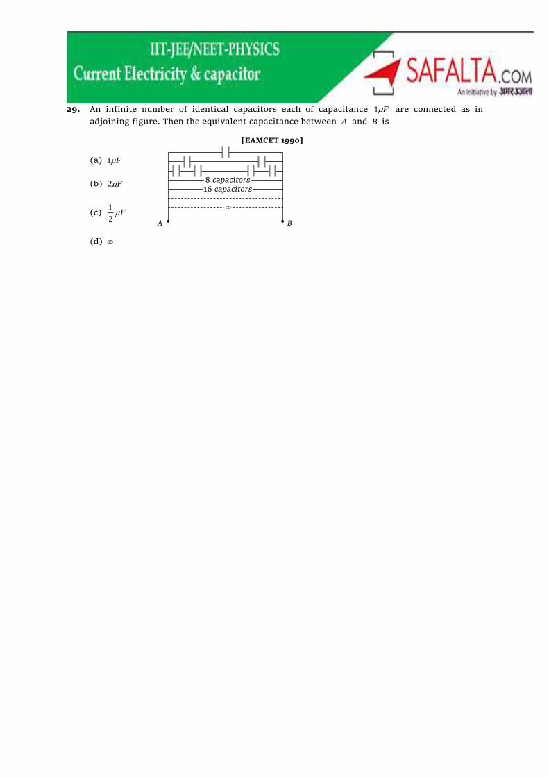
29. An infinite number of identical capacitors each of capacitance F1 are connected as in
adjoining figure. Then the equivalent capacitance between A and B is
[EAMCET 1990]
(a) F1
(b) F2
(c) F2
1
(d)
8 capacitors 16 capacitors
A B

30. Two condensers of capacities C2 and C are joined in parallel and charged upto potential V.
The battery is removed and the condenser of capacity C is filled completely with a medium
of dielectric constant K. The p.d. across the capacitors will now be [IIT 1988]
(a) 2
3
K
V (b)
K
V3
(c) 2K
V (d)
K
V

31. In the figure below, what is the potential difference between the point A and B and between
B and C respectively in steady state [IIT 1979]
(a) VVV BCAB 100 (b) VVVV BCAB 25,75
(c) VVVV BCAB 75,25 (d) VVV BCAB 50
3F
3F 1F
1F B
10
20 100V
A C
1F

32. In the given circuit if point C is connected to the earth and a potential of V2000 is given to
the point A, the potential at B is [MP PET 1997; Pb. PET 2003]
\ (a) V1500
(b) V1000
(c) V500
(d) V400
C
B A
5F
10F 10F
10F
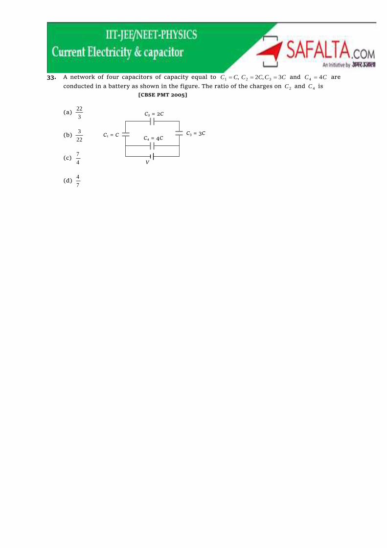
33. A network of four capacitors of capacity equal to CCCCCC 3,2, 321 and CC 44 are
conducted in a battery as shown in the figure. The ratio of the charges on 2C and 4C is
[CBSE PMT 2005]
(a) 3
22
(b) 22
3
(c) 4
7
(d) 7
4
V
C2 = 2C
C3 = 3C C1 = C C4 = 4C

34. Five identical plates each of area A are joined as shown in the figure. The distance between
the plates is d. The plates are connected to a potential difference of voltsV . The charge on
plates 1 and 4 will be [IIT 1984]
(a) d
AV
d
AV 00 2.
(b) d
AV
d
AV 00 2.
(c) d
AV
d
AV 00 2.
(d) d
AV
d
AV 00 2.
1 2 3 4 5 –
+
V

35. Figure (a) shows two capacitors connected in series and joined to a battery. The graph in
figure (b) shows the variation in potential as one moves from left to right on the branch
containing the capacitors, if [MP PMT 1999]
(a) 21 CC
(b) 21 CC
(c) 21 CC
(d) The information is not sufficient to decide the relation between 1C and 2C
C1 C2
(a)
Y
X
(b
)