1. instructions on use - hidramatic
TRANSCRIPT

10
1. Instructions on Use
As per directive 97/23/EC, article 3, paragraph 3 without CE-marking
1.1 General• the regulations for hydro accumulators applicable in the place
installed are to be observed prior to commissioning and dur-ing operation
• the operating organisation is solely responsible for compli-ance with the existing regulations
• documents supplied are to be stored carefully, they will be required by the assessor during periodic inspections
• commissioning only by trained specialist personnel
1.1.1 WarningJdo not solder or weld to the vessel or work by mechanical
meansJrisk of explosion on welding or solderingJrisk of bursting and loss of type approval if worked mechani-
callyJdo not charge hydro accumulators with oxygen or air:
risk of explosionJprior to working on hydraulic systems, de-pressurise the sys-
tem. Serious accidents can be caused in case of incorrect fitting
1.2 Safety devicesEquipping, installation and operation of hydro accumulators require the following safety equipment:• device to prevent excess pressure (type approved)• device for de-pressurising• pressure measurement device• test pressure gauge connection• shut-off device
Option:• electromagnetically operated device for de-pressurising• safety device against exceeding temperature.
JThe safety devices must not perform any regulation function!
1.3 Commissioning
1.3.1 Notes• filling pressure
– hydro accumulators are in general supplied in a ready to use state. The filling pressure (p0) is given on the accumu-lator housing.
– prior to commissioning the accumulator must be filled to the filling pressure specified by the operator.
• gas filling– hydro accumulators are only allowed to be filled with nitro-
gen class 4.0 very pure, N2 99,99 vol-%.• permissible operating temperature
– hydro accumulators from Integral Accumulator KG are suit-able for operating temperatures from –10 to +80 °C. For different temperatures, please contact us.
• installation position– any, keep space of 200 mm clear for test and filling device.
• fastening– the accumulator is to be fastened such that reliable fasten-
ing is ensured during vibration in operation or on the frac-ture of the pipework or gas pipe.Integral Accumulator KG offers suitable mounting clips.
• inspection prior to commissioning– the inspection prior to commissioning and periodic inspec-
tions are to be performed in accordance with the EU direc-tives (→ 5. European Directive on Pressure Equip. 97/23/EC (abridged information), from page 10.15).
1.3.2 Filling hydro accumulators that can be refilledA filling and test device is to be used to fill the accumulators. Here the operating instructions for the filling device used are to be observed.M Note: the pre-filling pressure changes with the gas tempera-ture. After filling or blowing off nitrogen, wait until the tempera-ture has settled prior to checking the gas pressure.

101.4 MaintenanceJWarning: prior to opening the hydro accumulator, the accu-mulator must be de-pressurised!
1.4.1 GeneralHydro accumulators from Integral Accumulator KG are largely maintenance-free after filling with gas.The following maintenance tasks are to be performed for malfunc-tion free operation and long service life:• check gas filling pressure• check safety devices and valves• check pipe connections• check accumulator fastening
1.4.2 Checking the gas filling pressure• inspection interval
– the filling pressure is to be checked at least once in the week following commissioning of the accumulator. If no gas loss is found, the second check is to be performed after 3 months. If again no pressure change is found, it is possi-ble to change to annual inspections
• measuring on the fluid side– connect pressure gauge with accumulator using pipe– alternatively the pressure gauge can be connected directly
to the bleed connection• procedure:
– fill accumulator with hydraulic fluid– close shut-off device– allow hydraulic fluid to flow out slowly by opening the de-
pressurising valve (temperature compensation)– during the emptying process, observe pressure gauge. As
soon as the filling pressure in the accumulator is reached, the pointer falls suddenly to zero
If differences are measured, it is first to be checked whether:– there are no leaks in pipes and valves– the changes are due to different ambient or gas tempera-
turesOnly if a fault is not found here, is it necessary to check the hydro accumulator.

10
2. Guidelines for Selection, Installation and Operation
2.1 GeneralHydro accumulators from Integral Accumulator have been in use in numerous branches of industry for many years and are proven components. Optimal function and long service life are however only achieved if specific selection criteria are observed and incorrect installations and incorrect operating conditions are avoided.
For improved understanding of the following sections, the most important expressions and terms are briefly explained here:
2.1.1 (Excess) operating pressureThe pressure in a hydro accumulator with fluid filling and in the hydraulic system.p1= lower operating pressurep2= upper operating pressurep3= max. permissible pressure in the hydro system
(pressure adjustment, pressure limiting, p3 ≤ 0,9 x p4)pm= mean operating pressure
2.1.2 Permissible excess operating pressure p4Max. pressure for which the hydro accumulator is designed and that can be found in the technical documentation and the marking (rating plate, lettering).
2.1.3 Gas filling pressure p0Pressure in the gas chamber in the hydro accumulator if the accu-mulator is not filled with fluid. The gas filling pressure is in general established at room temperature (20 °C).
2.1.4 Permissible pressure ratio p2/p0Figure stipulated by the manufacturer in relation to the flexing motion of the diaphragm and thus its service life, e.g. 8:1; this fig-ure should not be exceeded (use pressures as absolute figures).
2.1.5 Permissible pressure fluctuation range ∆ppermMax. permissible pressure difference p2 – p1 for 2 million load changes and p2 ≤ p4
Fig. 10.1 Inadmissible pressure peaks
Fig. 10.2 Permissible operating behaviour
p1
p2
p3
p4
Pres
sure
Not permissible
Permissible
p0
p2
p3
p4
p1
pm
Pres
sure
Time

102.2 Aspects on the selection of a hydro accumulator
2.2.1 Selection in relation to the perm. excess operating pressure p4
The hydro accumulator is to be selected such that the permissible excess operating pressure p4 is in all circumstances above the upper operating pressure p2 to be expected and also above any pressure peaks that may occur.Pressure peaks or pressure increases occur, e.g., due the switching of multiway valves and the resulting retardation of oil masses, retardation of fast moving masses, pressure translation in differen-tial circuits etc.In this respect it is highlighted that pressure peaks may be so short that they can often not be measured with the aid of damped meas-uring instruments such as pressure gauges. Safety valves also do not always react to such short pressure peaks.
2.2.2 Correct selection of the gas filling pressure p0The magnitude of the gas filling pressure is dependent on the operating pressures to be expected and the type of application.
The following figures can be used as general guidance:
• with pulsation dampingp0 = 0,6 to 0,8 x pm (pm = mean operating pressure)
• with surge damping or volume storagep0 = 0,6 to 0,9 x p1 (p1 = lower working pressure)
It is to be ensured that the gas filling pressure does not exceed the value 0,9 x p1 also at the operating temperature. The gas filling pressure established and specified at room temperature increases with increasing temperature in accordance with the gas laws.As a rule of thumb, a pressure increase of 10% for a 30 °C temper-ature increase can be expected.A gas filling pressure that is too low will result in high levels of fill-ing of the hydro accumulator and thus to unnecessarily high flexing loads on the diaphragm; this can result in a reduction in the service life of the diaphragm.
2.2.3 Gas lossesInadequate gas pressures can also be due to gas losses as a conse-quence of permeation processes. As elastic separating materials are not leak-proof in the absolute sense, gas filling molecules pass through the separating material, are dissolved in the operating fluid and transported to the reservoir where there can again sepa-rate from the fluid. The gas losses increase proportionally with the operating pressure and exponentially with the temperature. With conditions that are otherwise the same, gas losses will result in a faster reduction of the gas filling pressure on smaller hydro accu-mulators than on larger accumulators.
Estimates on possible gas losses or reductions in the gas filling pressure can be made by the manufacturer with detailed knowl-edge of the operating pressure and the operating temperature. From this information it is possible to estimate maintenance inter-vals (→ 2.5 Maintenance, page 10.6).A gas filling pressure that is too low from the start will be further reduced by gas pressure losses, and, under operating conditions that otherwise remain the same, a hydro accumulator will not be able to store the same volume of fluid. Diaphragms or bladders as separating components are overloaded resulting in a reduction in the service life. The damping capacity of the hydro accumulator will be reduced, and any pressure peaks that occur can exceed the per-missible excess operating pressure. For this reason the magnitude of the gas filling pressure is to be checked and increased at inter-vals to suit the application. The check can be performed very straightforwardly with the aid of a filling device DF... on the gas connection or by applying pressure to the fluid side using a method described briefly in → 2.5 Maintenance, page 10.6 and in more detail in → 4. Operating Instructions for Filling Device DFM, from page 9.55.
2.3 Correct installation
2.3.1 Safety-related equipmentAt least for stationary hydraulic applications, it can be assumed that hydro accumulators are subject to the European directive on pressure equipment. The most important elements of the safety-related equipment are the pressure measuring device (pressure gauge), device for the preventing excess pressure (safety valves), non-return valves and shut-off valves and devices for de-pressuris-ing (blow-off valves). The installation can be performed with indi-vidual components or integrated in the form of a safety block. This task can be made easier in that for entire groups of hydro accumu-lators, safety-related equipment is only required to be provided once (→ DIN 24 552).
2.3.2 FasteningHydro accumulators must be securely fastened such that movement cannot occur even on the facture of a pipe. Under no circumstances should hydro accumulators be fastened such that their mass is borne entirely by pipes. Special brackets, clips, mounts or female/feed through threads on the fluid connections can be used for secure fastening. If heavy vibration or shock loading is to be expected, please consult the manufacturer. The secure fastening of a hydro accumulator is be given the same importance as the checked and certified installation of a pressure vessel.

102.4 Operating states to be avoided
2.4.1 Excessively high pressure ratioAn excessively high pressure ratio between the upper operating pressure p2 and the gas filling pressure p0 is to be avoided for var-ious reasons. The max. permissible pressure ratio stated by the manufacturer takes into account a reasonable service life of dia-phragms or bladders. If the ratio is exceeded, a significant reduc-tion in the service life cannot be excluded. A further reason is that a hydro accumulator has a progressive characteristic curve, i.e. with increasing pressure the increase in the fluid volume stored per pressure unit becomes less and less. Expressed in a different way, the hydro accumulator becomes "harder and harder". In an appli-cation with volume storage, an increasing amount of (lost) energy must be expended to store less and less additional fluid.It is to be noted that the pressure ratio on bladder and piston accu-mulators with additional gas volume (additional cylinders) is not definitive due to the increased overall volume and should be replaced by an adjusted pressure ratio or, even better, by a permis-sible amount of filling.
2.4.2 Insufficient spacing of the gas filling pressure p0 from the lower operating pressure p1
If the gas filling pressure is greater than the lower operating pres-sure, the hydro accumulator empties itself completely during each operating cycle. Particularly on diaphragm accumulators, the seal-ing elements on the diaphragms sit on or hit the inside of the hous-ing in the area of the fluid connection. Continuous contact can cause flash to form or cause other material deformations that can in turn destroy the diaphragm.It is important to note that a correct gas filling pressure can reach excessively high value due to increasing temperature.Briefly passing the gas filling pressure during starting and shut down cannot be avoided and does not cause any damage.If continuous transition of the gas filling pressure cannot be avoided for functional reasons, it is strongly recommended to con-sult the manufacturer, as special designs are available for difficult cases.
2.4.3 Sudden complete draining of a hydro accumulatorApplications in which a hydro accumulator can empty suddenly and without control are to be avoided. One of the possible disadvan-tages has already be described in → 2.4.2 Insufficient spacing of the gas filling pressure p0 from the lower operating pressure p1. It is clear that the deformation at a sealing component or by a sealing com-ponent are all the greater, the harder the impact of the sealing component. A further disadvantage is that on the rapid outflow of fluid, flow forces can be produced that accelerate the sealing com-ponents onto its seat before the fluid has flowed out completely. In such cases oil pockets are formed, i.e. the available useful volume could not be utilised. The fluid volume left in the accumulator also
results in a fictional increase in the gas filling pressure that could also impair subsequent operating cycles. In extreme cases the sep-arating material can also enter the fluid connection due to the flow forces before the sealing component has reached its seat.This situation can be rectified by fixed regulators, regulator valves or pressure retention valves.
2.4.4 Sudden fillingSudden filling can cause damage to a diaphragm due to the high inflow speeds. If the filling process, e.g., occurs during surge damp-ing with complete emptying of the accumulator, a jet of fluid "shooting into the accumulator" can briefly over elongate the dia-phragm "stuck" to the inside wall and sooner or later destroy it. Fixed regulators and regulator valves can also be used to rectify this situation.
2.4.5 Raised temperaturesThe usual operating conditions for hydro accumulators is between–10 °C and +80 °C. Higher temperatures are possible with sepa-rating components (bladders, diaphragms) made of special mate-rials. However, here the progressively increasing gas losses (→ 2.2.3 Gas losses, page 10.4) with raised temperatures must be taken into account. In addition, a reduction in the permissible excess operating pressure is to be expected, as the strength figures for the housing material must also be reduced.
2.4.6 Low temperaturesAt temperatures below –10 °C, the elasticity of the standard mate-rials (NBR) for diaphragms and bladders reduces and there is a risk of fractures. If usage at such low temperatures cannot be avoided, special separating wall materials must be used. Please
Fig. 10.3 Pressure curve on complete emptying
p0
p2
p4
p1
Pres
sure
Time
Continuously passing throughthe gas filling pressure pis to be avoided!
0

10consult the manufacturer. It is also to be noted that not all housing materials are suitable or approved for low temperatures, as a drop in the notch impact strength can occur. In usage a differentiation is to be made between temperatures due to weather conditions and low temperatures of the medium stored. The manufacturer will be pleased to provide more information.
2.4.7 Incorrect operating mediumHydro accumulators are designed as standard for use with mineral oil. If other fluids like water or even aggressive chemicals are to be used, hydro accumulators that meet these requirements in relation to the housing material, corrosion protection and the compatibility of their separating materials must be used. Along with housing damage (rust, pitting), swollen or shrunk and thus soon useless diaphragms or bladders are to be feared. It is imperative to consult the manufacturer.
2.5 MaintenanceAlong with the external inspection for corrosion damage and cor-rect fastening, the maintenance of a hydro accumulator is limited to the regular checking and correction if necessary of the gas filling pressure. While for volume storage, variations in the gas filling pressure is mostly to be noticed in the form of inadequate function, for pulsation damping or surge damping, incorrect gas filling pres-sure can remain undetected for long periods and cause damage to the hydro accumulators or the system.For the check, filling devices should be used that are offered by the manufacturer for the various types of gas connections (M28x1,5 or filling valves with Vg8 filling connection) and at the same time can also be used for the connection to a pressure reducer connected to nitrogen cylinder for the correction or changing of the gas filling pressure.If only the magnitude of the gas filling pressure is to be deter-mined, this task can also be performed on the fluid side, if it is pos-sible to slowly fill or drain the hydro accumulator.During slow filling, the filling process will be seen to slow consid-erably when the gas filling pressure is reached. During draining, after a slowing in the pressure drop, a sudden pressure drop to zero occurs, which can be clearly seen on a pressure gauge. This process can be performed if necessary within a system without removing the accumulator. If the effective storage temperature during the test is different to room temperature RT, the result must be converted to RT=20 °C.The usage of filling devices with the accumulator installed, requires, of course, along with complete fluid side draining, good access to the gas connections and adequate clearance above them.
2.6 DisposalHydro accumulators as sealed hollow bodies are not allowed to be included unopened in scrap for smelting, as per German accident prevention regulation VBG 111. It is therefore necessary to de-pressurise hydro accumulators on the gas side by carefully unscrew-ing gas filling screws or gas filling valves and opening the accumu-lator. Filling devices are also well suited to this task.On special designs with a permanently sealed gas filling opening (disposable accumulators) only careful drilling (∅ ≥ 6 mm) of the gas chamber in a suitable retaining jig can be used. As the gas flowing out can draw metal splinters or particles with it, safety glasses must be worn.
Fig. 10.4 Checking the gas filling pressure on the fluid side
0
p4
pOT
During filling: significant redu ction in therate of increase of the pressure
Pres
sure
Stored volume
During draining: sudden drop in pressureto zero

10
3. Calculation and Design
Almost all formulas for the calculation of hydro accumulators are based on the state changes or gas equations for ideal gases. Even though it is known that nitrogen, as the filling gas most frequently used, at high pressures and/or low temperatures has the behaviour of a real gas, which can be significantly different to the behaviour of an ideal gas, the formulas given below have proven surprisingly useful in practice for pressure ranges to around 200 bar for initial approximate calculations. Also other important effects such as the viscosity of the fluid, length and size of pipes or connections, valve closing times, moved masses etc. at times are not known at all, or at least their effect on the entire circuit is not known in detail and therefore more or less accurate assumptions must be made.For the more detailed analysis of a problem and its optimal solu-tion, today along with complex simulation calculations, trials are still to be recommended that should be performed at the operating organisation under practical conditions, as these are more realistic than any conditions set up in the laboratory. In general it can be assumed that the calculation of static applications produces more accurate results than the calculations of dynamic processes.
d = inside diameter of a pipef0 = natural frequency of an accumulatork = pump factorl = pipe lengthn = polytropic exponentp = pressure (as absolute value)p0 = gas filling pressure at room temperaturep0T = gas filling pressure at temperature Tp1 = lowest operating pressurep2 = largest operating pressurepm = mean pressure during pulsespSt = isothermal achieved steady state pressure(p2/p0T)perm = permissible pressure ratio∆p = pressure difference, range of fluctuations∆pperm = perm. pressure difference p4–p1Q = flow rateT = absolute temperature in KT1 = temperature at p1; V1T2 = temperature at p2; V2V0 = gas volume without fluid fillingV1 = gas volume at p1V2 = gas volume at p2
VH = stroke volume of an individual piston on a reci-procating pump
VSt = gas volume at pSt∆V = fluid volume stored between two pressuresZ = calculated table valueδ = residual pulse (p2–pm)/pmε = pm/p0κ = 1,4 (adiabatic exponent)ρ = density of a fluid
3.1 Isothermal state changesIsothermal state changes reflect the state after very slow changes on full temperature compensation or an adequately long period of time after change.The curves with the pressures on the abscissa and the volume stored on the ordinate appear in a double logarithmic scale as straight lines (→ Fig. 10.5), in a system with linear scales however lines with a curve to the right.
Fig. 10.5 Equation (2)
p0 p1 p2
∆V
Stor
ed vo
lume
V∆
Pressure p

10(1)
(2)
3.2 Polytropic state changesOn polytropic state changes the heat exchange with the surround-ing environment is at least partially suppressed. On the occurrence of pressure increases in the gas, a temperature increase therefore takes place. Conversely, on a reduction in pressure the temperature drops. If, during fast processes, temperature compensation does not occur, the change approaches the adiabatic in which the poly-tropic exponent n is replaced by the adiabatic exponent κ = 1,4 (for nitrogen N2 as two atom gas). For real gases n can also be cho-sen larger than 1,4.
Recommended: p0 = 0,6 x p1 to 0,8 x p1
(3)
(4)
3.3 Isothermal charging with subsequent polytropic state change
Frequently practical applications are a mixture of isothermal and polytropic state changes. After a slow isothermal charging or start-ing from a steady state, e.g., on a surge or a sudden withdrawal of the stored pressure medium, a polytropic state change can occur. In the calculation, first the gas volume VSt is determined isothermally at the steady state pressure pSt, these two variables are then con-sidered initial parameters in the context of V0 and p0 for the subse-quent polytropic state change.
Recommended: p0 = 0,6 x p1 to 0,8 x p1
(5)
(6)
Special case: polytropic charging to p2 starting from p1=pSt
(7)
Special case: polytropic discharging to p1 starting from p2=pSt∆V is negative (withdrawal!)
(8)
Fig. 10.6 Polytropic state change
p V⋅ const.=
p0 V0⋅ p1 V1⋅ p2 V2⋅= =
∆V p0 V01p1---- 1
p2----–
⋅ ⋅=
p0 p1 p2
∆V
Stor
ed vo
lume
V∆
Pressure p
Isothermal
Polytropic
p Vn⋅ const.=
p Vn⋅ p1 V1n⋅ p2 V2
n⋅= =
∆V V0p0
p1----
1n--
p0
p2----
1n--
–⋅=
Fig. 10.7
p0 p1 p2
∆V
∆V
∆V
p1p2 p0 p0 p2=pStp=pStpSt
Pressure p
Isothermal
Polytropic
Isothermal
Polytropic
Isothermal
Polytropic
VSt V0p0
pSt-----⋅=
∆V V0p0
pSt-----
pSt
p1-----
1n--
pSt
p2-----
1n--
–⋅ ⋅=
∆V V0p0
p1---- 1
p1
p2----
1n--
–⋅ ⋅=
∆V V0p0
p2---- 1
p2
p1----
1n--
–⋅ ⋅=
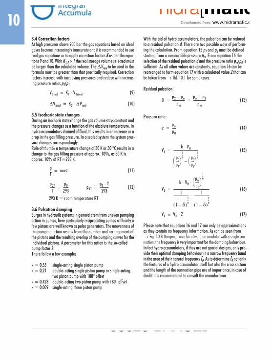
103.4 Correction factorsAt high pressures above 200 bar the gas equations based on ideal gases become increasingly inaccurate and it is recommended to use real gas equations or to apply correction factors K as per the equa-tions 9 and 10. With K1,2 > 1 the real storage volume selected must be larger than the calculated volume. The ∆Vreal to be used in the formula must be greater than that practically required. Correction factors increase with increasing pressures and reduce with increas-ing pressure ratios p2/p1.
(9)
(10)
3.5 Isochoric state changesDuring an isochoric state change the gas volume stays constant and the pressure changes as a function of the absolute temperature. In hydro accumulators drained of fluid, this results in an increase or a drop in the gas filling pressure. In a sealed system the system pres-sure changes correspondingly.Rule of thumb: a temperature change of 30 K or 30 °C results in a change to the gas filling pressure of approx. 10%, as 30 K is approx. 10% of RT=293 K.
(11)
(12)
293 K = room temperature RT
3.6 Pulsation dampingSurges in hydraulic systems in general stem from uneven pumping action in pumps, here particularly reciprocating pumps with only a few pistons are well known as pulse generators. The unevenness of the pumping action results from the number and arrangement of the pistons and the resulting overlap of the pumping curves for the individual pistons. A parameter for this action is the so-called pump factor k.There follow a few examples:
k = 0,55 single-acting single piston pumpk = 0,21 double-acting single piston pump or single-acting
two piston pump with 180° offsetk = 0,423 double-acting two piston pump with 180° offsetk = 0,009 single-acting three piston pump
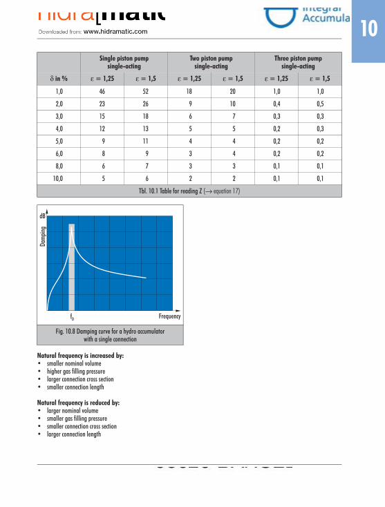
With the aid of hydro accumulators, the pulsation can be reduced to a residual pulsation d. There are two possible ways of perform-ing the calculation. From equation 15 p1 and p2 must be defined starting from a measurable pressure pm. From equation 16 the selection of the residual pulsation d and the pressure ratio pm/p0 is sufficient. As all other values are constants, equation 16 can be rearranged to form equation 17 with a calculated value Z that can be taken from → Tbl. 10.1 for some cases.
Residual pulsation:
(13)
Pressure ratio:
(14)
(15)
(16)
(17)
Please note that equations 16 and 17 can only be approximations as they contain no frequency information. As can be seen from → Fig. 10.8 Damping curve for a hydro accumulator with a single con-nection, the frequency is very important for the damping behaviour. In fact hydro accumulators, if they are not special designs, only pro-vide their optimal damping behaviour in a narrow frequency band in the area of their natural frequency f0. As to determine f0 not only the features of a hydro accumulator itself but also the cross section and the length of the connection pipe are of importance, in case of doubt it is recommended to consult the manufacturer.
V0real K1 V0ideal⋅=
∆Videal K2 ∆Vreal⋅=
pT-- const.=
p0T
T------
p0
293------= p0T
p0 T⋅293
----------=
δp2 pm–
pm---------------
pm p1–pm
---------------= =
εpm
p0-----=
V0k VH⋅
p0
p1----
1n--
p0
p2----
1n--
–
-----------------------------=
V0
k VHpm
p0-----
1n--
⋅ ⋅
1
1 δ–( )1n--
------------------ 1
1 δ–( )1n--
------------------–------------------------------------------=
V0 VH Z⋅=
10
Natural frequency is increased by:• smaller nominal volume• higher gas filling pressure• larger connection cross section• smaller connection length
Natural frequency is reduced by:• larger nominal volume• smaller gas filling pressure• smaller connection cross section• larger connection length
Single piston pumpsingle-acting
Two piston pumpsingle-acting
Three piston pumpsingle-acting
δ in % ε = 1,25 ε = 1,5 ε = 1,25 ε = 1,5 ε = 1,25 ε = 1,5
1,0 46 52 18 20 1,0 1,0
2,0 23 26 9 10 0,4 0,5
3,0 15 18 6 7 0,3 0,3
4,0 12 13 5 5 0,2 0,3
5,0 9 11 4 4 0,2 0,2
6,0 8 9 3 4 0,2 0,2
8,0 6 7 3 3 0,1 0,1
10,0 5 6 2 2 0,1 0,1
Tbl. 10.1 Table for reading Z (→ equation 17)
Fig. 10.8 Damping curve for a hydro accumulatorwith a single connection
dB
fD Frequency
Dam
ping
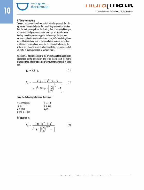
103.7 Surge dampingThe most frequent cause of surges in hydraulic systems is fast clos-ing valves. In the calculation the simplifying assumption is taken that the entire energy from the flowing fluid is converted into gas work within the hydro accumulator during a pressure increase. Starting from the pressure p1 prior to the surge, the pressure increase must not exceed a stipulated value p2. Valve closing times are not taken into account in the calculation, nor are connection resistances. The calculated value for the nominal volume on the hydro accumulator to be used is therefore to be taken as an initial estimate. It is recommended to perform trials.
A position as close as possible to the production of the surge is rec-ommended for the installation. The surge should reach the hydro accumulator as directly as possible without many changes in direc-tion.
(18)
(19)
Using the following values and dimensions
ρ = 890 kg/m n = 1,4l in m d in mmQ in l/min V0 in lp1 and p2 in bar
the equation is:
(20)
p0 0,8 p1⋅=
V02 ρ 1 Q2 n 1–( )⋅ ⋅ ⋅ ⋅
π d2 0,8 p1p2
p1----
n 1–n
----------
1–⋅ ⋅ ⋅ ⋅
------------------------------------------------------------------=
V07,87 10 4– l Q2⋅ ⋅ ⋅
d2 p1p2
p1----
0,28571–⋅ ⋅
-------------------------------------------------=

10
4. Recommended Oil Types
M For normal operating conditions we recommend the usage of mineral oil based hydraulic oils HL and HLP as per the following list. For special conditions, it is also possible to use HLPD and HVLP oils with the same viscosity classes. Prior to the usage of HE fluids (HEPG, HETG and HEES biodegradable oils) or HFC (flame retard-ant water-glycol mixtures) we request you to contact us.The order of the manufacturers listed is alphabetical and therefore not a ranking. The list also makes no claim to completeness. In general it is based on the information from the manufacturers and as such we cannot provide any guarantee in relation to the content. It is to be noted that some fluids cover a large viscosity range (e.g. 32–68) and are therefore only mentioned once.
VG 46 VG 68Mineral oil company/manufacturer
a) HL 1) (mineral oil) e) HEPG (polyglycol-based)b) HLP 2) (mineral oil) f) HETG (vegetable oil)c) HVLP 3) (mineral oil) g) HEES (synth. ester)d) HLPD 4) (mineral oil) h) HFC (water/glycol)
ARALa) Aral Vitam UF 46 Aral Vitam UF 68b) Aral Vitam GF 46 Aral Vitam GF 68c) Aral Vitam HF 46
Aral Vitam VF 46Aral Vitam VF 68
d) Aral Vitam DE 46 Aral Vitam DE 68e) Aral Vitam BAF 46 –f) – –g) Aral Vitam EHF 46 –h) Aral Montral 44 –
BECHEMa) – –b) Staroil No. 46 Staroil No. 68c) Staroil HVI 46 Staroil HVI 68d) Staroil H-LPD 46 Staroil H-LPD 68e) Hydrostar UWF 46 Hydrostar UWF 68f) UWS Hydraulik 32 –g) Hydrostar HEP 46 Hydrostar HEP 68h) Hydrostar HY 46 –
BPa) BP Energol HL 46 –b) BP Energol HLP-HM 46 BP Energol HLP-HM 68c) Bartran HV 46 Bartran HV 68d) BP Energol HLP-D 46 BP Energol HLP-D 68e) – –f) Carelube HTG 32 –g) Biohyd SE 46 Biohyd SE 68h) Enersyn SF-C 14 –
CASTROLa) Magna 46 Magna 68b) Hyspin AWS 46
Hyspin SP 46Hyspin AWS 68Hyspin SP 68
c) Hyspin AWH-M 46 Hyspin AWH-M 68d) Vario HDX 46
hydraulic oil HLP-D 46 SFVario HDX 68hydraulic oil HLP-D 68 SF
e) – –f) Carelube HTG 32 Carelube HTG 68g) Castrol product 695/13
Carelube HES 46Castrol product 695/14Carelube HES 68
h) Anvol WG 46 –DEA
a) Astron HL 46 Astron HL 68b) Astron HLP 46
Astron X HLP 46Astron HLP 68Astron X HLP 68
c) Astron HVLP 46Astron X HVLP 46
Astron HVLP 68
d) Actis HLPD 46Actis X HLPD 46Trion EP 46
Actis HLPD 68Actis X HLPD 68Trion EP 68
e) Econa PG 46 –f) (Econa R 32) –g) Econa E46 –h) Tectro HF-C 46 S –
VG 46 VG 68Mineral oil company/manufacturer
a) HL 1) (mineral oil) e) HEPG (polyglycol-based)b) HLP 2) (mineral oil) f) HETG (vegetable oil)c) HVLP 3) (mineral oil) g) HEES (synth. ester)d) HLPD 4) (mineral oil) h) HFC (water/glycol)

10
ELFa) ELF POLYTELIS 46 ELF POLYTELIS 68b) ELFOLNA 46
ELFOLNA DS 46ELFOLNA SP 46
ELFOLNA 68ELFOLNA DS 68ELFOLNA SP 68
c) HYDRELF DS 46 HYDRELF DS 68d) ELFOLNA HLPD 46
ELFOLNA HMD 46ELFOLNA HLPD 68ELFOLNA HMD 68
e) – –f) ELF XTD 93031 –g) HXDRELF BIO –h) PYRELF HFC 46 –
ESSOa) TERESSO 46 TERESSO 68b) NUTO H 46
Hydraulic oil HLP 46NUTO H 6Hydraulic oil HLP 68
c) UNIVIS N 46 UNIVIS N 68d) HLPD oil 46 HLPD oil 68e) Hydraulic oil PGK 46 –f) Hydraulic oil PFL –g) Hydraulic oil HE 46 –h) – –
FINAa) CIRKAN 46 CIRKAN 68b) HYDRAN 46 HYDRAN 68c) HYDRAN HV 46 HYDRAN HV 68d) HYDRAN HLP-D 46
Hydraulic oil D3033HYDRAN HLP-D 68
e) Hydraulic oil D3031-46 –f) BIOHYDRAN RS 38 –g) BIOHYDRAN SE 38
BIOHYDRAN TMP 46BIOHYDRAN TMP 68
h) – –FRAGOL
a) – –b) Hydraulic oil HLP 46 Hydraulic oil HLP 68c) Hydraulic oil HVLP 46 Hydraulic oil HVLP 68d) Hydraulic oil HLP-D 46 Hydraulic oil HLP-D 68e) Fragol Hydraulic TR 46 –f) Fragol Hydraulic V32 –g) Fragol Hydraulic HE 46 FRAGOL Hydraulic HE 68h) Fragol Hydrolub 125
Fragol Hydrolub NF 46-DFRAGOL Hydrolub 126
VG 46 VG 68Mineral oil company/manufacturer
a) HL 1) (mineral oil) e) HEPG (polyglycol-based)b) HLP 2) (mineral oil) f) HETG (vegetable oil)c) HVLP 3) (mineral oil) g) HEES (synth. ester)d) HLPD 4) (mineral oil) h) HFC (water/glycol)
FUCHSa) RENOLIN DTA 46 RENOLIN DTA 68b) RENOLIN B15VG 46
RENOLIN ZAF 46 BRENOLIN B15VG 68RENOLIN ZAF 68 B
c) RENOLIN MR 46 MCRENOLIN ZAF 46 MC
RENOLIN MR 68 MCRENOLIN ZAF 68 MC
d) RENOLIN MR 15 VG 46RENOLIN D 15 VG 46RENOLIN ZAF 46 D
RENOLIN MR 15 VG 68RENOLIN D 15 VG 68
e) RENOLIN PG 46 RENOLIN PG 68f) PLANTOHYD 46 N
PLANTOHYD NPLANTOHYD 68 N
g) PLANTOHYD 46 SPLANTOHYD 46 HVIPLANTOHYD Super S
PLANTOHYD 68 S
h) Hydrotherm 46 MHydrotherm 46 NF 3
–
MOBILa) Vactra Oil Medium
DTE Oil MediumVactra Oil Heavy MediumDTE Oil Heavy Medium
b) Mobil DTE 25 Mobil DTE 26c) Mobil DTE 15 M Mobil DTE 16 Md) Hydraulic oil HLPD 46 Hydraulic oil HLPD 68e) – –f) Mobil EAL 224 H –g) Mobil EAL Syndraulic 46
Hydraulic Oil UF 46–
h) Hydrofluid LTNyvac FR 200 D Fluid
–
OESTa) Hydraulic oil H-L 46 Hydraulic oil H-L 68b) Hydraulic oil H-LP 46 Hydraulic oil H-LP 68c) Hydraulic oil HVI 46 Hydraulic oil HVI 68d) Hydraulic oil 46 DD Hydraulic oil 68 DDe) – –f) (BIO HY-FLUID HV 34) (BIO HY-FLUID HV 68)g) Bio Synthetik HYD 46 Bio Synthetik HYD 68h) – –
PANOLINa) Panolin Indol ISO 46 Panolin Indol ISO 68b) Panolin HLP ISO 46 Panolin HLP ISO 68c) Panolin HLP Universal 37 Panolin GP 55d) Panolin HLP-D ISO 46 Panolin HLP-D ISO 68e) – –f) – –g) Panolin HLP Synth 46 Panolin HLP Synth 68h) – –
VG 46 VG 68Mineral oil company/manufacturer
a) HL 1) (mineral oil) e) HEPG (polyglycol-based)b) HLP 2) (mineral oil) f) HETG (vegetable oil)c) HVLP 3) (mineral oil) g) HEES (synth. ester)d) HLPD 4) (mineral oil) h) HFC (water/glycol)

10
1) normally hydraulic oil in accordance with DIN 51524 part 12) normally hydraulic oil in accordance with DIN 51524 part 23) normally hydraulic oil in accordance with DIN 51524 part 34) like 2) or 3), however detergent action
PETROFERa) Isolubric VG 46 L Isolubric VG 68 Lb) Isolubric VG 46 Isolubric VG 68c) Isolubric VG 46 HV Isolubric VG 68 HVd) Isolubric VG 46 D Isolubric VG 68 De) Syntolubric 46 –f) Syntolubric 32 –g) Envolubric HE 46 Envolubric HE 68h) Ultra-Safe 620 Ultra-Safe 360
QUAKERa) – –b) – –c) – –d) – –e) – –f) GREENSAVE N 30 –g) GREENSAVE N 40 –h) QUINTOLUBRIC 730 –
SHELLa) Morlina Oil 46 –b) Shell Tellus Oil 46 Shell Tellus Oil 68c) Shell Tellus Oil TD 46 –d) Shell Tellus Oil DO 46 Shell Tellus Oil DO 68e) Shell Fluid BD 46 –f) Shell Naturelle HF-R –g) Shell Naturelle HF-E 46 Shell Naturelle HF-E 68h) – –
STUARTa) – –b) – –c) – –d) – –e) ISOCOR E 46 –f) – –g) ISOCOR HF 46 ISOCOR HF 68h) HYDROVOR CC 44 –
TEBIOLa) – –b) – –c) – –d) – –e) – –f) Florahyd HVI 46 Florahyd HVI 68g) Esterhyd HE 46 –h) – –
VG 46 VG 68Mineral oil company/manufacturer
a) HL 1) (mineral oil) e) HEPG (polyglycol-based)b) HLP 2) (mineral oil) f) HETG (vegetable oil)c) HVLP 3) (mineral oil) g) HEES (synth. ester)d) HLPD 4) (mineral oil) h) HFC (water/glycol)
TRIBOLa) Tribol 772 Tribol 773b) Tribol 943 AW 46 Tribol 943 AW 68c) – –d) – –e) – –f) – –g) Tribol 1448/46 Tribol 1448/68h) – –
WISURAa) Dynex 46 Dynex 68b) Tempo 46 Tempo 68c) Hydroma 46 Hydroma 68d) HLPD 46 HLPD 68e) – –f) Hydroma NAT 40 –g) Hydrofluid SE 46 –h) – –
VG 46 VG 68Mineral oil company/manufacturer
a) HL 1) (mineral oil) e) HEPG (polyglycol-based)b) HLP 2) (mineral oil) f) HETG (vegetable oil)c) HVLP 3) (mineral oil) g) HEES (synth. ester)d) HLPD 4) (mineral oil) h) HFC (water/glycol)

10
5. European Directive on Pressure Equip. 97/23/EC (abridged information)
5.1 GeneralIt is generally known that the free trade in hydro accumulators and other pressure vessels is made more difficult by different national regulations and the related different acceptance limits, calculation methods and acceptance methods. In Brussels efforts have there-fore been underway for some time to create standard regulations. The
directive 97/23/EC of the European Parliament and of the Council of 29 May 1997 on the approximation of the laws of the Member States concerning pressure equipment
was published in the official journal of the European Union on 9.7.97 under No. L18. According to article 20 the member states must have adopted the necessary laws, regulations and adminis-trative provisions by 29 May 1999. From 29 November 1999 the new regulations can be applied. Up until 29 May 2002 pres-sure vessels are also allowed to be placed on the market in accord-ance with the previous regulations.
5.2 Important points in the directive in relation to hydro accumulators
• the directive applies to hydro accumulators (= pressure equipment) with more than 0,5 bar overpressure.
• exempt are hydro accumulators for the operation of vehicles that have been awarded type approval based on other Euro-pean directives. Also exempt are hydro accumulators that would fall in the area of the Machinery directive 89/392 and correspond as a maximum with category I (see below). Also hydro accumulators fitted in ships, offshore plant and aircraft are exempt.
• hydro accumulators with nitrogen as the gas filling and min-eral oil with a flame point above the perm. operating temper-ature (is actually always the case), are categorised in (hazard) group 2 both on the gas side and the fluid side; this group has increased exemption limits compared to the group 1 that applies to dangerous media (article 9).
• hydro accumulators are subject to a so-called declaration of conformity assessment as a function of the hazard groups, pressures, volumes and/or pressure-volume products to be applied. If certain limits are passed, they are classified in cat-
egories (I to IV) to which so-called modules are allocated; a detailed description of this aspect goes beyond the scope of this summary. As on the usage of nitrogen and mineral oil, the more severe conditions are produced in relation to nitrogen (gas), diagram 2 (→ Fig. 10.9) is to be used for hydro accu-mulators.It can be seen that all accumulators with V ≤ 1 l or V > 1 l and PS x V ≤ 50 bar ⋅ l (→ Fig. 10.9, grey area) are below the cat-egories, unless PS > 1000 bar (PS = max. perm. working pressure in bar).
• hydro accumulators that fall in the categories I to IV receive a CE marking. Hydro accumulators outside the categories (grey area) are not allowed to be given a CE marking. However they are permitted to participate in the free movement of goods when they comply with good engineering practice in a mem-ber state in relation to design and manufacture (article 3(3)).
• commissioning and periodic inspections:As no statements are made on this issue in the European direc-tive for pressure equipment, we recommend maintaining pre-vious practice.Previous practice requires that prior to initial commissioning, a hydro accumulator system must be subject to an acceptance test at the operating organisation; this test is to comprise a check on regulations, the installation and the equipment.On hydro accumulators up to category I, a specialist is allowed to perform and certify the acceptance test, while for hydro accumulators of category II an independent assessor (e.g. TÜV) must accept the test and certify it.Periodic inspections, e.g., every 2 years are allowed to be per-formed by a specialist up to and including category II.

10
The modules allocated to the categories provide information on the responsibilities during the design, manufacture and examinations. Thus, e.g., on the application of module A the manufacturer is solely responsible. Module H is to have a particularly high value for certified companies.
I = module AII = modules A1, D1, E1III = modules B1+D, B1+F, B+E, B+C1, HIV = modules B+D, B+F, G, H1
A = internal manufacturing checks (only manufacturer)A1 = like A, with random sample monitoring of the final
assessmentB = EC type examinationB1 = EC design examinationC1 = conformity of the typeD, D1, E, E1 = various quality assurance measuresF = testing of the productsG = EC unit verificationH = full quality assuranceH1 = like H, with design examination and final assessment
surveillance
Fig. 10.9 Diagram 2 for gases (e.g. nitrogen) in hazard group 2
PS (bar)10 000
1 000
100
10
10,5
10,11 10 100 1 000 10 000 V(I)
PS=5 000
PS=1 000 PSxV=5 000
PSxV=1 000
PSxV=200PSxV=50
PS=0,5I
IV
II III
IV
III
V=1
PS=4WithoutCE markingarticle 3, paragraph 3
WithCE marking