1. introduction 2. determination of circuit resistance …
TRANSCRIPT


1. INTRODUCTION
2. DETERMINATION OF CIRCUIT RESISTANCE
3. DETERMINATION OF POWER SUPPLY REQUIREMENTS
4. SELECTION OF POWER SUPPLY TYPE
5. RECTIFIER SELECTION
6. ANODES FOR IMPRESSED CURRENT SYSTEMS
7. OTHER SYSTEM COMPONENTS
This is what we will talk about today….
© J. Paul Guyer 2014 All Rights Reserved pdhsource.com

J. PAUL GUYER, P.E., R.A.
Paul Guyer is a registered Mechanical Engineer, Civil
Engineer, Fire Protection Engineer and Architect with 35
years building and infrastructure design experience. For
an additional 9 years he was a principal advisor to the
California Legislature on infrastructure and capital outlay
issues. He is a graduate of Stanford University and has
held a number of national, state and local positions with
the American Society of Civil Engineers, Architectural
Engineering Institute, National Society of Professional
Engineers, National Council of Engineering Examiners,
and Accreditation Board for Engineering and
Technologies.
© J. Paul Guyer 2014 All Rights Reserved pdhsource.com

1. INTRODUCTION. There are two principle methods of providing
cathodic protection: sacrificial anode and impressed current. The primary
advantage of impressed current cathodic protection systems over
sacrificial anode cathodic protection systems is that the driving potential
of the impressed current systems is not limited by the corrosion potential
of an active metal. The ability to select appropriate driving potentials, and
to adjust the driving potential after system installation, gives the designer
and operator of impressed current cathodic protection systems additional
flexibility to compensate for changing environmental conditions. The
primary advantage of this variable driving potential in the design of
impressed current cathodic protection systems is the ability to select the
location of anode beds for an optimum distribution of protective current
with a minimum of interference. The variable driving potential available in
impressed current systems also allows the protection of structures in
high resistivity environments where the output of sacrificial anodes is
severely limited. The primary operational benefit of variable driving
potential is the ability to adjust the system for changes in soil resistivity,
anode condition, structure surface (coating) condition and additions to
the structure.
© J. Paul Guyer 2014 All Rights Reserved pdhsource.com

2. DETERMINATION OF CIRCUIT RESISTANCE. In the design of
impressed current cathodic protection systems the first step is the
determination of the total current required for the system. This fixes the
output current required for the system power supply. The next step is the
determination of the required output or driving potential that will be
required. As the output current is fixed, the required driving potential will
be determined by the total circuit resistance and the back potential
offered by the structure-to-anode potential. The equivalent circuit is
shown in Figure 1. In most impressed current systems, the major factor
in the determination of the total circuit resistance is the anode-to-
electrolyte resistance.
2.1 ANODE-TO-ELECTROLYTE RESISTANCE. Also known as "ground
bed resistance," this is often the highest resistance in the impressed
current cathodic protection system circuit.
© J. Paul Guyer 2014 All Rights Reserved pdhsource.com

2.1.1 EFFECT ON SYSTEM DESIGN AND PERFORMANCE. As shown
in Figure 1, the anode-to-electrolyte resistance, if high, is the most
important factor in the determination of the driving potential required to
provide the current required for effective cathodic protection in impressed
current cathodic protection systems. Anode-to-electrolyte resistance can
be varied within wide limits by the use of different sized anodes and the
use of multiple anodes. The lowest anode-to-electrolyte resistance
commensurate with total system cost is desirable since it will reduce the
power costs by lowering the output potential of the power supply. This
lower power supply output potential also results in higher reliability for
other system components, particularly the insulation on cables, splices,
and connections. In general, anode bed resistances below 2 ohms are
desirable.
© J. Paul Guyer 2014 All Rights Reserved pdhsource.com
2. DETERMINATION OF CIRCUIT RESISTANCE.

© J. Paul Guyer 2014 All Rights Reserved pdhsource.com
2. DETERMINATION OF CIRCUIT RESISTANCE.
Figure 1
Equivalent Cathodic Protection Circuit

© J. Paul Guyer 2014 All Rights Reserved pdhsource.com
2. DETERMINATION OF CIRCUIT RESISTANCE.
2.1.2 CALCULATION OF ANODE-TO-ELECTROLYTE RESISTANCE.
Anode-to-electrolyte resistance can be computed from data on anode type,
size, shape, and configuration of multiple anode arrays plus the soil
resistivity. First, the type, size, and shape of the anode to be used is
chosen. Then, the resistance of a single anode to be used is calculated.
Then the effect of the use of multiple anodes is determined. However, as
the actual environmental resistivity may not be uniform, or may undergo
seasonal variations, the calculation of anode-to-electrolyte resistivity should
only be considered to be an approximation of the actual resistance to be
encountered. This can result in the actual driving potential required being
somewhat different than the potential calculated using the approximate
anode bed resistance. Thus, after installation, the driving potential must be
adjusted to give the required current output. As the other potentials and
resistances in the cathodic protection circuit vary, the system will also
require periodic adjustments.
2.1.3 BASIC EQUATIONS. The formulae developed by H. B. Dwight for a
single cylindrical anode can be used to determine the anode-to-electrolyte
resistance. The formula for a vertically oriented anode is:

© J. Paul Guyer 2014 All Rights Reserved pdhsource.com
2. DETERMINATION OF CIRCUIT RESISTANCE.
The formula for a horizontally oriented anode is:

© J. Paul Guyer 2014 All Rights Reserved pdhsource.com
2. DETERMINATION OF CIRCUIT RESISTANCE.
2.1.4 SIMPLIFIED EXPRESSIONS FOR COMMON SITUATIONS. For
many common situations, the Dwight formulae have been simplified by
combining terms and eliminating terms that have insignificant values in
most cases. Some of these simplified formulae have been given in para.
2.6. In addition to these simplified formulae, the following simplified formula
is often used:
2.1.4.1 RESISTANCE OF A SINGLE VERTICAL ANODE.

© J. Paul Guyer 2014 All Rights Reserved pdhsource.com
2. DETERMINATION OF CIRCUIT RESISTANCE.

© J. Paul Guyer 2014 All Rights Reserved pdhsource.com
2. DETERMINATION OF CIRCUIT RESISTANCE.
2.1.4.2 PARALLELING OF ANODES. Common practice to reduce
anode bed resistance is to connect several anodes in parallel in a
group. The resistance of a group of anodes is less than the
resistance for a single anode but is greater than that calculated from
the usual parallel resistance formula due to interactions between the
fields surrounding each anode. If the anodes are arranged in a
parallel row, the resistance of a group of anodes can be
approximated by the following formula:

© J. Paul Guyer 2014 All Rights Reserved pdhsource.com
2. DETERMINATION OF CIRCUIT RESISTANCE.

© J. Paul Guyer 2014 All Rights Reserved pdhsource.com
2. DETERMINATION OF CIRCUIT RESISTANCE.
If multiple rows of anodes are used where the spacing between rows is more
than 4 times the spacing between the anodes in each row, the usual parallel
resistance formula:
may be used.
2.1.4.3 SPECIAL FORMULA FOR WATER TANKS. For water tanks where
circular arrays of anodes are commonly used and where the structure
surrounds the anodes and electrolyte, special formulae have been developed
to calculate the anode-to-electrolyte resistance. For a single cylindrical anode,
the formula developed by E. R. Shepard may be used. The formula is as
follows:

© J. Paul Guyer 2014 All Rights Reserved pdhsource.com
2. DETERMINATION OF CIRCUIT RESISTANCE.
The anodes are usually arranged in a circular array in the tank bowl. The
optimum diameter of this array can be determined by the following formula:

© J. Paul Guyer 2014 All Rights Reserved pdhsource.com
2. DETERMINATION OF CIRCUIT RESISTANCE.
If four or more anodes are used in a circular array, the following modified
Shepard formula should be used to calculate the resistance of the array:

© J. Paul Guyer 2014 All Rights Reserved pdhsource.com
2. DETERMINATION OF CIRCUIT RESISTANCE.

© J. Paul Guyer 2014 All Rights Reserved pdhsource.com
2. DETERMINATION OF CIRCUIT RESISTANCE.
2.1.5 FIELD MEASUREMENT. Calculations, as previously discussed, can
give good approximations of anode-to-electrolyte resistance under actual
conditions. While these calculations can be effectively used for system design,
if the environment is well known, the actual anode-to-electrolyte resistance
that is encountered is sometimes sufficiently different from the calculated
value to require adjustment or modification of the system. The actual anode-
to-electrolyte resistance can also be determined by actual field
measurements.
2.1.5.1 ANODE FIRST METHOD. In this method of determining anode-to-
electrolyte resistance, the anodes are installed as designed and the actual
resistance between the anode or anode bed and the structure to be protected
is measured. This measurement includes both the anode-to-electrolyte
resistance and the structure-to-electrolyte resistance and can be used to
determine the required driving potential so that the proper power supply can
be ordered. This is the most accurate method of sizing the needed rectifier
and should be used where practical.

© J. Paul Guyer 2014 All Rights Reserved pdhsource.com
2. DETERMINATION OF CIRCUIT RESISTANCE.
2.1.5.2 POWER SUPPLY FIRST METHOD. In this method, the power supply
is ordered based upon the calculated circuit resistance and is installed and
connected to the structure. The anodes are installed as planned, but one at a
time. The total circuit resistance is calculated based upon the actual power
supply output in amperes and volts. If additional anodes are required in order
to achieve the desired anode-to-electrolyte resistance, they can be installed at
this time at a relatively low cost since the equipment required for installation is
on site and excavations for the anode lead cables are open.

© J. Paul Guyer 2014 All Rights Reserved pdhsource.com
2. DETERMINATION OF CIRCUIT RESISTANCE.
2.1.6 EFFECT OF BACKFILL. Backfill is very important and is usually used to
surround impressed current anodes in order to reduce anode-to-electrolyte
resistivity, to increase porosity around the anodes to insure that any gasses
formed during operation will be properly vented, and to reduce polarization
effects and reduce localized dissolution of the anode. Under favorable
circumstances, the anode-to-electrolyte resistivity can be reduced to one-half
through the use of backfill. In extremely low resistance environments such as
seawater, graphite and high silicon cast iron anodes can be used without
backfill; otherwise, impressed current anodes should always be used with
backfill. In high resistivity environments where the use of backfill is impractical,
graphite anodes should not be used. High silicon chromium bearing cast iron
(HSCBCI) anodes can be used with or without backfill in most instances. The
cost of using backfill should be evaluated on an economic basis with the
reduction in the power requirements or the of anodes required being the cost
reduction factors. If the resistivity of the backfill is less than one-tenth the soil
resistivity, then the voltage drop through the backfill becomes negligible.

© J. Paul Guyer 2014 All Rights Reserved pdhsource.com
2. DETERMINATION OF CIRCUIT RESISTANCE.
a) Thus, the effective diameter of the anode is the diameter of the backfill
rather than the diameter of the anode itself. As can be evaluated through
calculation of anode-to-electrolyte resistance, this can result in a significant
reduction in anode-to-electrolyte resistance which can be useful in reducing
the number of anodes required, the required driving potential, or both. Backfill
for impressed current anodes is carbonaceous material from several sources.
It can be either coke breeze (crushed coke), flake graphite, or round particle
petroleum coke. Experience has shown that round particle calcined petroleum
coke has many advantages over coke breeze made from coal. Specification
"Loresco DW-2" or equal should be used for surface anode beds and Loresco
DW-3 or equal for deep anode beds. Because the material can be pumped
and has good porosity and particle-to-particle contact, round particle
petroleum coke backfill is the most desirable material and its higher cost will
be justified for most installations, particularly for "deep anodes."

© J. Paul Guyer 2014 All Rights Reserved pdhsource.com
2. DETERMINATION OF CIRCUIT RESISTANCE.
b) In areas where the soil is extremely wet or loose, such as in a swampy
area, it may not be possible to properly install or tamp the backfill material.
Packaged anodes with the backfill contained in metal cylinders (cans)
surrounding the anodes may be useful in these circumstances but increase
the cost. Anodes prepackaged with backfill, usually contained in metal cans
which are rapidly corroded away during operation, are easier to install than
separate installation of anode and backfill. The prepackaged anodes are
higher in cost and have the following additional disadvantages:

© J. Paul Guyer 2014 All Rights Reserved pdhsource.com
2. DETERMINATION OF CIRCUIT RESISTANCE.
(1) High unit weight reduces ease of handling.
(2) Possibility of voids developing in backfill during transportation and
handling.
(3) The critical anode cable and connection between the anode and cable are
hidden and difficult to inspect.
The choice of packaged versus unpackaged impressed current anodes must
be made based upon economics and local site conditions. Packaged anodes
are usually used only where unstable soil conditions exist, where the hole
excavated for installation caves in, and where prepackaged anodes are
stocked for augmenting systems.
2.2 STRUCTURE-TO-ELECTROLYTE RESISTANCE. The structure-to-
electrolyte resistance is commonly disregarded in the design of impressed
current cathodic protection systems since it is usually very small with respect
to the anode-to-electrolyte resistance. When total circuit resistance is
measured (refer to para. 2.1.5), the structure-to-electrolyte resistance is
included in the value obtained.

© J. Paul Guyer 2014 All Rights Reserved pdhsource.com
2. DETERMINATION OF CIRCUIT RESISTANCE.
2.3 CONNECTING CABLE RESISTANCE. The connecting cable resistance is
determined by the size and length of cables used.
2.4 RESISTANCE OF CONNECTIONS AND SPLICES. In addition to the
factthat connections and splices are sources of resistance in impressed
current cathodic protection systems, they are a site of failure. These
connections should be kept to an absolute minimum, and they should be very
carefully assembled, insulated, inspected, and installed. The cable from the
positive lead of the power source to the anodes carries a high positive charge
and will deteriorate rapidly at any point where the insulation is breached and
the conductor contacts the electrolyte. The number and location of each
connection should be installed per the system design and not at the discretion
of the installer.
3. DETERMINATION OF POWER SUPPLY REQUIREMENTS. The power
supply requirements, namely current and voltage, are determined by Ohm's
Law from the required current for protection of the structure and the calculated
or measured total circuit resistance. The actual power supply requirement
should allow for future loads and rectifier aging. Generally, a factor of 1.5 over
calculated output is used.

© J. Paul Guyer 2014 All Rights Reserved pdhsource.com
2. DETERMINATION OF CIRCUIT RESISTANCE.
2.3 CONNECTING CABLE RESISTANCE. The connecting cable resistance is
determined by the size and length of cables used.
2.4 RESISTANCE OF CONNECTIONS AND SPLICES. In addition to the
factthat connections and splices are sources of resistance in impressed
current cathodic protection systems, they are a site of failure. These
connections should be kept to an absolute minimum, and they should be very
carefully assembled, insulated, inspected, and installed. The cable from the
positive lead of the power source to the anodes carries a high positive charge
and will deteriorate rapidly at any point where the insulation is breached and
the conductor contacts the electrolyte. The number and location of each
connection should be installed per the system design and not at the discretion
of the installer.

© J. Paul Guyer 2014 All Rights Reserved pdhsource.com
3. DETERMINATION OF POWER SUPPLY REQUIREMENTS. The power
supply requirements, namely current and voltage, are determined by Ohm's
Law from the required current for protection of the structure and the calculated
or measured total circuit resistance. The actual power supply requirement
should allow for future loads and rectifier aging. Generally, a factor of 1.5 over
calculated output is used.

© J. Paul Guyer 2014 All Rights Reserved pdhsource.com
4. SELECTION OF POWER SUPPLY TYPE. Any source of direct current of
appropriate voltage and current can be used as a source of power for
impressed current cathodic protection systems. The selection of power supply
depends upon local conditions at the site and should be evaluated based upon
life cycle cost including maintenance and availability of ac power or fuel.
4.1 RECTIFIERS. Rectifiers are by far the most commonly used power supply
type for impressed current cathodic protection systems. They are available in
a wide variety of types and capacities specifically designed and constructed
for use in impressed current cathodic protection systems. The most commonly
used type of rectifier has an adjustable step down transformer, rectifying units
(stacks), meters, circuit breakers, lightning arresters, current measuring
shunts, and transformer adjusting points (taps), all in one case.

© J. Paul Guyer 2014 All Rights Reserved pdhsource.com
4.2 THERMOELECTRIC GENERATORS. These power supplies convert heat
directly into direct current electricity. This is accomplished through a series of
thermocouples which are heated at one end by burning a fuel and cooled at
the other, usually by cooling fins. Thermoelectric generators are highly reliable
since they have few, if any, moving parts. They are available in sizes from 5 to
500 W. They are very expensive and should only be considered for remote
locations where electrical power is not available and fuel is available. They are
used as a power supply for impressed current cathodic protection on remote
pipelines where the product in the pipeline can be used as a fuel.
4.3 SOLAR. A photovoltaic solar cell converts sunlight directly into direct
current electricity. The cost per W is high but is decreasing as solar cell
technology is improved. Solar panels are used for cathodic protection power
supplies at remote sites where neither electrical power or fuel is available. In
order to supply current continuously, solar cells are used in a system that
supplies power to the system and recharges batteries when sunlight is
received. When sunlight is not being received, the batteries supply the
required current.
4. SELECTION OF POWER SUPPLY TYPE.

© J. Paul Guyer 2014 All Rights Reserved pdhsource.com
4.4 BATTERIES. When current requirements are low, storage batteries can be
used to supply power for impressed current cathodic protection systems at
remote sites. They must be periodically recharged and maintained.
4.5 GENERATORS. Engine- or wind-driven generators can be used to supply
direct current power for impressed current cathodic protection systems at sites
where ac power is not available.
4. SELECTION OF POWER SUPPLY TYPE.

© J. Paul Guyer 2014 All Rights Reserved pdhsource.com
5. RECTIFIER SELECTION. The rectifier selected for a specific impressed
current cathodic protection application must be matched to both the electrical
requirements and the environmental conditions at the site. Rectifiers are
available in many electrical types and specifically designed for use in
impressed current cathodic protection systems in many environments.
5.1 RECTIFIER COMPONENTS. Figure 2 is a circuit diagram for a typical
single-phase full-wave bridge type rectifier showing the components found in
most standard rectifiers of this type. The diagram also shows an external
switch and circuit protection device which is mandatory for many rectifier
installations.
5.1.1 TRANSFORMER COMPONENT. The transformer reduces the incoming
alternating current voltage to the alternating current voltage required for the
operation of the rectifing component. In most impressed current cathodic
protection rectifiers, the voltage output from the secondary windings can be
varied by changing the effective number of secondary windings through a
system of connecting bars or "taps." Two sets of taps are normally present,
one for coarse adjustments and one for fine adjustments. By manipulation of
these taps, the voltage should be adjustable to vary the rectifier voltage from
zero, through at least 20 equal steps, to its maximum capacity.

© J. Paul Guyer 2014 All Rights Reserved pdhsource.com
5.1.2 RECTIFYING ELEMENTS. The alternating current from the secondary
windings of the transformer element is converted to direct current by the
rectifying elements or "stacks." The stack is an assembly of plates or diodes
and may be in several configurations. The most common rectifying elements
are selenium plate stacks and silicon diodes. Each has advantages and
disadvantages. The most common configurations of rectifying elements are
the single-phase bridge, single-phase center tap, three-phase bridge, and
three-phase wye. The rectifying elements allow current to flow in one direction
only and produce a pulsating direct current. The rectifying elements do allow a
small amount of alternating current to pass. This "ripple" is undesirable and
should be held to low levels. Rectifiers are not 100 percent efficient in
converting alternating current to direct current. This is due to the presence of
alternating current and to inherent losses in the rectifying elements which
result in heating of the stacks. Silicon elements are more efficient than
selenium elements at high output voltages but are more susceptible to failure
due to voltage overloads or surges. The efficiency of a rectifying element is
calculated by the following equation:
5. RECTIFIER SELECTION.

© J. Paul Guyer 2014 All Rights Reserved pdhsource.com
5. RECTIFIER SELECTION.
Typical efficiencies of single-phase rectifying elements are in the order of 60 to
75 percent but can be increased by filtering the output or by using a three-phase
circuit.
5.1.3 OVERLOAD PROTECTION. Overload protection in the form of either
circuit breakers, fuses, or both should be used on all impressed current rectifiers.
In addition to protecting the circuits from overloads, circuit breakers provide a
convenient power switch for the unit. Circuit breakers are most commonly used
on the alternating current input to the rectifiers and fuses are most commonly
used on the direct current outputs. In addition to circuit breakers and fuses, the
rectifier should be furnished with lightning arresters on both the ac input and dc
output in order to prevent damage from lightning strikes or other short duration
power surges. The respective firing voltages of the lightning arresters should be
higher than the ac input and dcoutput voltage. Due to their susceptibility to
damage from voltage surges, silicon diodes shall also be protected by selenium
surge cells or varistors and by current limiting fuses against over-current surges.
A high speed rectifier fuse should be installed in one leg of the ac secondary and
one in the dc negative output leg.

© J. Paul Guyer 2014 All Rights Reserved pdhsource.com
5. RECTIFIER SELECTION.
Figure 2
Single phase – full-wave bridge rectifier

© J. Paul Guyer 2014 All Rights Reserved pdhsource.com
5. RECTIFIER SELECTION.
5.1.4 METERS. In order to conveniently measure the output current and
potential, the rectifier should be furnished with meters for reading these
values. The meter should not be continuously operating but should be
switched into the circuit as required. This not only protects the meter from
electrical damage from surges but, when the meter is read, it moves from
zero to the indicated reading. Frozen meter movements are easily detected
in this manner. Often, one meter and a two position switch are used to
measure both potential and current. Current is usually measured using an
external current shunt. Output voltage and current can also be conveniently
measured by the use of portable meters used across the rectifier output and
the current shunt.

© J. Paul Guyer 2014 All Rights Reserved pdhsource.com
5. RECTIFIER SELECTION.
5.2 STANDARD RECTIFIER TYPES
5.2.1 SINGLE-PHASE BRIDGE. The circuit for this type of rectifier is shown
in Figure 2. This type of rectifier is the most commonly used type of rectifier
up to an output power of about 1,000 W. Above 1,000 W, the extra cost of
three-phase types is often justified by the increased electrical efficiency of
the three-phase units. The rectifying unit consists of four elements. If any
one of the rectifying elements fails or changes resistance, the other elements
usually also fail. Current passes through pairs of the rectifying elements
through the external load (structure and anode circuit). The active pair of
elements alternates as the polarity of the alternating current reverses while
the other pair blocks the flow of current. The result is full-wave rectified
current as shown in Figure 3.
© J. Paul Guyer 2014 All Rights Reserved pdhsource.com
5. RECTIFIER SELECTION.
5.2.2 SINGLE-PHASE CENTER TAP. The circuit of a single-phase center
tap rectifier is shown in Figure 4. This type of rectifier has only two rectifying
elements but produces full-wave rectified output. However, since only one-
half of the transformer output is applied to the load, the transformer required
is considerably heavier and more costly than in single-phase bridge type
units. This type of unit is also less sensitive to adjustment than the single-
phase bridge type; however, it is electrically more efficient.
5.2.3 THREE-PHASE BRIDGE. The circuit for a three-phase bridge rectifier
is shown in Figure 5. The circuit operates like three combined single-phase
bridge circuits that share a pair of diodes with one of the other three bridges.
There are three secondary windings in the transformer that produce out-of-
phase alternating current supplied to each pair of rectifying elements. This
out-of-phase relationship produces a direct current output with less
alternating current "ripple" than the single-phase type, only 4.5 percent. Due
to the reduction in alternating current ripple, three-phase bridge rectifiers are
more electrically efficient than the single-phase types, and the extra initial
cost of the unit is often justified by savings in supplied power, particularly for
units of over 1,000 W capacity.

© J. Paul Guyer 2014 All Rights Reserved pdhsource.com
5. RECTIFIER SELECTION.
Figure 3
Full-wave rectified current

© J. Paul Guyer 2014 All Rights Reserved pdhsource.com
5. RECTIFIER SELECTION.
Figure 4
Single-phase – center tap circuit

© J. Paul Guyer 2014 All Rights Reserved pdhsource.com
5. RECTIFIER SELECTION.
Figure 5
Three-phase bridge circuit

© J. Paul Guyer 2014 All Rights Reserved pdhsource.com
5. RECTIFIER SELECTION.
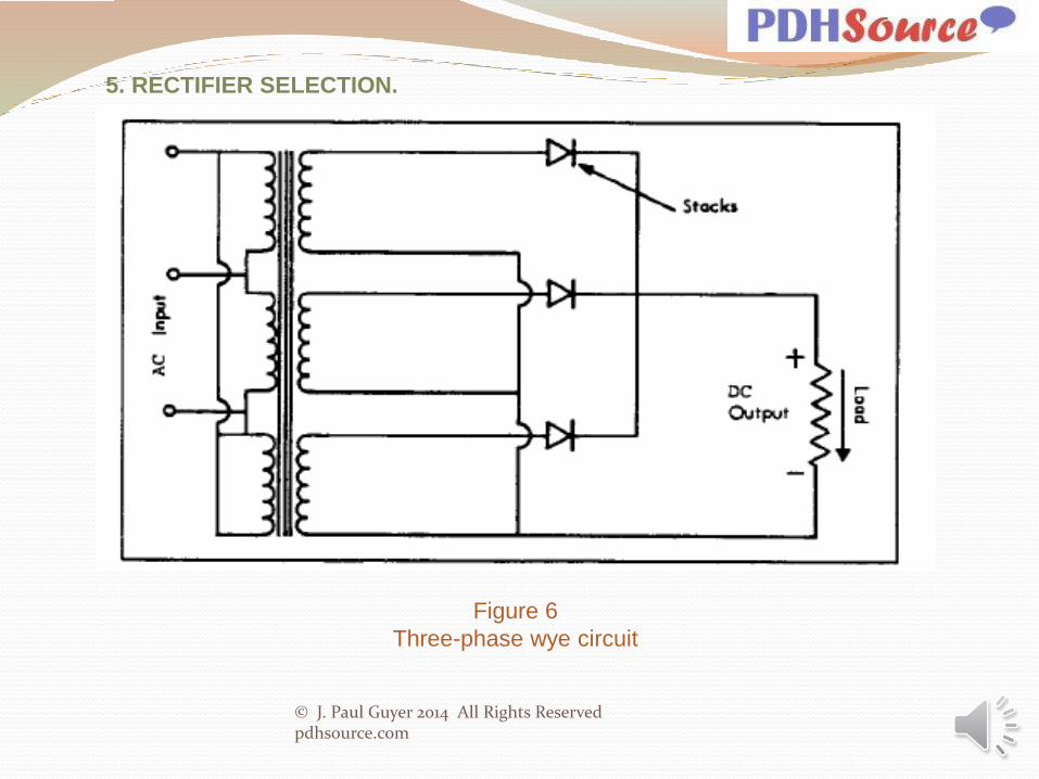
5.2.4 THREE-PHASE WYE. The circuit for a three-phase wye rectifier is shown
in Figure 6. This type of rectifier supplies half-wave rectified current as shown in
Figure 7. The power to the rectifier unit is supplied by three separate windings on
a transformer, but only three rectifying elements, each in series with the output,
are provided. This type of rectifier unit is practical only for systems requiring low
output voltages.
5.2.5 SPECIAL RECTIFIER TYPES. Several special of rectifiers, specifically
designed for use in cathodic protection systems have been developed for special
applications. Some special rectifiers provide automatic control of current to
maintain a constant structure-to-electrolyte potential. Others provide a constant
current over varying external circuit resistances, or other features desirable in
specific circumstances.

© J. Paul Guyer 2014 All Rights Reserved pdhsource.com
5. RECTIFIER SELECTION.
(a) A constant current rectifier is depicted by a block diagram in Figure 8. A direct
current input signal to the power amplifier is supplied from an adjustable resistor in
the output signal. The power amplifier uses this “feedback” signal to adjust the
voltage supplied to the stack so that a constant input signal and, therefore, a
constant output current is supplied. The power amplifier may either be of an
electronic (silicon controlled rectifier) or saturable reactor type.
b) An automatic potential control type is shown by a block diagram in Figure 9.
This type of unit uses the potential between the structure and a reference
electrode to control the output current of the unit. As in the constant current type
of rectifier, the power amplifier can be of the electronic or saturable reactor type.
These rectifiers are commonly used where the current requirement or circuit
resistance varies greatly with time such as in the case of a a structure in an area
with high periodic tidal currents or a water storage tank where the water level
changes considerably.
© J. Paul Guyer 2014 All Rights Reserved pdhsource.com
5. RECTIFIER SELECTION.
Figure 6
Three-phase wye circuit

© J. Paul Guyer 2014 All Rights Reserved pdhsource.com
5. RECTIFIER SELECTION.
Figure 7
Half-wave rectified circuit

© J. Paul Guyer 2014 All Rights Reserved pdhsource.com
5. RECTIFIER SELECTION.
Figure 8
Constant current rectifier

© J. Paul Guyer 2014 All Rights Reserved pdhsource.com
5. RECTIFIER SELECTION.
Figure 9
Constant potential rectifier

© J. Paul Guyer 2014 All Rights Reserved pdhsource.com
5. RECTIFIER SELECTION.
c) Multicircuit constant current type is depicted by a circuit diagram in Figure 10.
This type of rectifier is designed to provide a small, constant current in the order
of 100 mA to a single anode. As the resistance of the internal resistor is high
when compared with the external circuit resistance, the output current is
controlled by the value of this resistor. The output potential will vary up to the line
voltage to supply the specified output current. In this type of circuit, the structure
is connected directly to the neutral lead of the alternating current power supply.
Due to problems associated with stray currents and the possible presence of
high voltages external to the rectifier units, the use of this type of rectifier is not
recommended. Several standardized rectifiers have been developed for
commercial applications such as natural gas and electrical distribution system
protection. The use of a standardized unit allows for economy of production and
reduction in overall cost of the unit as well as the installation and maintenance of
the unit. Where a large number of similar capacity units are to be used, the
selection of a standardized type of rectifier should be considered.
5.3 RECTIFIER SELECTION AND SPECIFICATIONS. Rectifiers can either be
selected from "stock" units or can be custom manufactured to meet specific
electrical and site-related requirements. Many features are available either as
"add on's" to stock units or in custom units.

© J. Paul Guyer 2014 All Rights Reserved pdhsource.com
5. RECTIFIER SELECTION.
Figure 10
Multicircuit constant current rectifier

© J. Paul Guyer 2014 All Rights Reserved pdhsource.com
5. RECTIFIER SELECTION.
5.3.1 AVAILABLE FEATURES. Features now available on most units include:
• a) Constant voltage or current output
• b) Multiple circuits in the same enclosure
• c) Air cooled or oil immersed
• d) Any commercial input voltage
• e) Three phase or single phase
• f) Center tap or bridge
• g) Wide range of output currents and voltages
• h) Efficiency filters to reduce ac ripple
• i) Interference noise filters
• j) Explosion proof enclosures
• k) Small arms proof enclosures
• l) Lightning protection on both ac input and dc output
• m) Surge protection on both ac input and dc output
• n) Silicon diodes or selenium stacks
• o) Painted or galvanized cases
• p) Various mounting legs or brackets
• q) Units designed for direct burial
• r) External "on-off" indicators
• s) Variety of price, quality and warranty
• t) Maintenance free anodized aluminum enclosure

© J. Paul Guyer 2014 All Rights Reserved pdhsource.com
5. RECTIFIER SELECTION.
Factors that should be considered in selecting appropriate features for a specific
application are given below.
5.3.2 AIR COOLED VERSUS OIL IMMERSED. Rectifiers can be supplied as
either entirely air cooled, entirely oil immersed or with the stacks only oil
immersed. Air-cooled units are lowest in cost and easiest to install and repair.
However, oil-cooled units should be specified where corrosive or dirty
atmospheric conditions are encountered or where explosive gasses may be
present. The controls should not be immersed in the oil. Air-cooled units require
more frequent maintenance to clean the air screens and other components and
are also susceptible to damage by insects and other pests. Older oil-cooled units
were supplied with oils containing polychlorinated biphenyls (PCBs) which have
been determined to be carcinogenic and are no longer supplied with new units.
Units containing PCBs should be treated according to current policy regarding
PCBs.

© J. Paul Guyer 2014 All Rights Reserved pdhsource.com
5. RECTIFIER SELECTION.
5.3.3 SELECTING AC VOLTAGE. Select alternating current voltages of almost
any commercial power supply voltage. Units with either 115 V, 230-V or 440-V
single-phase or 208-, 230-, or 440-V three-phase inputs are the most common.
Some units are supplied with dual input voltage selected by wiring arrangements
during installation. Choices between single-phase and three-phase units should
be based upon a balance between first cost and efficiency. The following table
can be used to select the combinations of rectifier capacity and input voltages
which are commonly most economical if a selection of supply voltages is
available:

© J. Paul Guyer 2014 All Rights Reserved pdhsource.com
5. RECTIFIER SELECTION.
5.3.4 DC VOLTAGE AND CURRENT OUTPUT. Direct current voltage outputs
from 8 to 120 V and current outputs from 4 A to 100 A are common. Almost any
current can be provided but it is generally best to select a smaller standard size
rectifier unit such as 20 A and use multiple units if very large amounts of current
are required. Many small units cause far less interference and provide more
uniform current distribution along the protected structure than few large units.
5.3.5 FILTERS. Electrical filters are used to both increase the efficiency of the
rectifier by reducing alternating current ripple and to reduce interference with
communications equipment. Efficiency filters can increase the efficiency of
single-phase bridge type rectifiers by 10 to 14 percent and their use should be
based upon a first cost versus operating (power) cost basis. Efficiency filters are
not commonly used with three-phase rectifiers as the alternating current ripple in
these units is inherently low. Noise interference filters should be used when a
large unit is to be installed in the vicinity of communications lines or can be
retrofitted when noise problems are encountered and are significantly affected by
turning the unit on and off.

© J. Paul Guyer 2014 All Rights Reserved pdhsource.com
5. RECTIFIER SELECTION.
5.3.6 EXPLOSION PROOF RECTIFIERS. Rectifiers and other system
components such as switch and circuit breakers are available in explosion proof
enclosures conforming to Electrical Safety Standards for Class I Group D
hazardous conditions that may be encountered in fuel or natural gas storage or
distribution systems. Such enclosures should be specified whenever explosive
hazards may exist.
5.3.7 LIGHTNING ARRESTERS. Lightning arresters should always be used on
both the ac input and dc output sides of rectifiers using silicon rectifying
elements. Their use on units using selenium elements is recommended in areas
where lightning strikes are frequent. The arresters on the output should have a
firing voltage greater than the rectifier output voltages.

© J. Paul Guyer 2014 All Rights Reserved pdhsource.com
5. RECTIFIER SELECTION.
5.3.8 SELENIUM VERSUS SILICON STACKS. While some old installations
used copper oxide rectifying elements, modern units use either silicon or
selenium rectifying elements. In general, silicon units are used for larger units
where their higher efficiency is more important than their lower reliability.
Ordinary selenium stacks deteriorate with time. This "aging" can be reduced by
variations in plate composition and "non-aging" stacks are available. Aging rates
are determined by operating temperatures that are a function of current flow. The
selection of a unit using selenium rectifying elements which has a somewhat
greater capacity than required will increase stack life. The efficiency of selenium
rectifying elements is a function of operating voltage versus rated voltage as
shown in Figure 11. Silicon diodes are mounted in metal cases which are
mounted on either aluminum or copper plates to dissipate the heat generated
during operation. Silicon diodes do not age as do selenium stacks and, as shown
in Figure 12, are more efficient than selenium elements, particularly at higher
voltage ratings. Silicon rectifying elements are more subject to complete failure
from voltage surges which would only cause increased aging of selenium stacks.
Surge protection should always be used on both the ac input and dc output of
rectifiers using silicon diode rectifying elements.

© J. Paul Guyer 2014 All Rights Reserved pdhsource.com
5. RECTIFIER SELECTION.
5.3.9 OTHER OPTIONS. Other features listed in para. 5.3.1 are available and
should be selected as appropriate. In remote off-base areas, small arms proof
enclosures may be required based upon local experience. Specifying clear
anodized aluminum enclosure top coated with one clear coat of polyurethane will
reduce maintenance painting.
5.3.10 RECTIFIER ALTERNATING CURRENT RATING. The ac current
requirement for a rectifier can be determined based upon rectifier output and
efficiency by the following formulae:

© J. Paul Guyer 2014 All Rights Reserved pdhsource.com
5. RECTIFIER SELECTION.

© J. Paul Guyer 2014 All Rights Reserved pdhsource.com
5. RECTIFIER SELECTION.
Figure 11
Efficiency versus voltage – selenium stacks

© J. Paul Guyer 2014 All Rights Reserved pdhsource.com
5. RECTIFIER SELECTION.
Figure 12
Efficiency versus voltage –
silicon stacks

© J. Paul Guyer 2014 All Rights Reserved pdhsource.com
6. ANODES FOR IMPRESSED CURRENT SYSTEMS. Although any
electrically conductive material can serve as an anode in an impressed current
system, anode materials that have a low rate of deterioration when passing
current to the environment are mechanically durable. These anode materials are
available in a form and size suitable for application in impressed current cathodic
protection systems at a low cost. While abandoned “in-place” steel such as
pipelines and rails can, and are, used as anodes, they are consumed at a rate of
about 20 lb/amp-year. The most commonly used purchased materials for
impressed current anodes are graphite, high silicon cast iron, high silicon
chromium bearing cast iron, aluminum, platinized titanium, platinized tantalum,
platinized niobium and silverized lead. Newly developed anode materials such
as oxide coated ceramics show considerable promise and should be evaluated
based upon experience in similar applications, particularly if the more commonly
used anode materials have proven unsatisfactory in a specific application.

© J. Paul Guyer 2014 All Rights Reserved pdhsource.com
6. ANODES FOR IMPRESSED CURRENT SYSTEMS.
6.1 GRAPHITE ANODES. Graphite anodes are the most commonly used
material for impressed current anodes in underground applications. They are
made by fusing coke or carbon at high temperatures and are sealed from
moisture penetration by being impregnated with a synthetic resin, wax, or linseed
oil to reduce porosity and increase oxidation resistance. An insulated copper
cable is attached to the anode internally for electrical connection to the rectifier.
This connection must be well sealed to prevent moisture penetration into the
connection and must be strong to withstand handling. The most important single
improvement in high silicon cast iron and graphite anodes is placing the lead
wire connection in the center of the anode instead of the end. This eliminates
end-effect, where ends of the anode are consumed 1-1/2 times faster than the
center. Although more expensive, the anode life is nearly doubled (tubular
anodes will be 95 percent consumed, whereas end connected anodes will be
only 50 percent consumed before the anode-to-lead wire connection is lost). This
also allows for a more effective seal of the lead wire connection. Nearly all anode
sizes are available in tubular form where the lead wire connection is located in
the center. Typical anodes, connections, and seals are shown in Figures 13 and
14.

© J. Paul Guyer 2014 All Rights Reserved pdhsource.com
6. ANODES FOR IMPRESSED CURRENT SYSTEMS.
6.1.1 SPECIFICATIONS. The following are typical specifications for
commercially available graphite anodes.

© J. Paul Guyer 2014 All Rights Reserved pdhsource.com
6. ANODES FOR IMPRESSED CURRENT SYSTEMS.
6.1.2 AVAILABLE SIZES. Graphite anodes are commercially available in two
sizes:
The weights given are for the graphite only and do not include the weight of
the lead wire or connection.

© J. Paul Guyer 2014 All Rights Reserved pdhsource.com
6. ANODES FOR IMPRESSED CURRENT SYSTEMS.
Figure 13
Anode to cable connection –
graphite anode

© J. Paul Guyer 2014 All Rights Reserved pdhsource.com
6. ANODES FOR IMPRESSED CURRENT SYSTEMS.
Figure 14
Center connected graphite anode

© J. Paul Guyer 2014 All Rights Reserved pdhsource.com
6. ANODES FOR IMPRESSED CURRENT SYSTEMS.
6.1.3 CHARACTERISTICS. All products from the operation or deterioration of
graphite anodes are gasses. In fresh water or non-saline soil, the principal gasses
produced are carbon dioxide and oxygen. In saline soils or in seawater, chlorine
is also produced and is the major gas produced in seawater applications. The
gasses generated, if allowed to collect around the anode, can displace moisture
around the anode which results in a local increase in soil resistivity and an
increase in circuit resistance.
6.1.4 OPERATION. Graphite anodes must be installed and operated properly in
order to insure optimum performance and life.
6.1.4.1 CURRENT DENSITIES. The current densities in the following table should
not be exceeded in order to obtain optimum anode life:

© J. Paul Guyer 2014 All Rights Reserved pdhsource.com
6. ANODES FOR IMPRESSED CURRENT SYSTEMS.

© J. Paul Guyer 2014 All Rights Reserved pdhsource.com
6. ANODES FOR IMPRESSED CURRENT SYSTEMS.
6.1.4.2 OPERATING POTENTIALS. Since the potential difference between steel
and graphite is approximately 1.0 V with the graphite being the cathode, this
potential difference must be overcome before protective current will begin to flow
in the impressed current cathodic protection system circuit. This 1.0 V must be
added to the other voltage and IR drop requirements during the selection of
proper power supply driving voltage.
6.1.4.3 CONSUMPTION RATES. Assuming uniform consumption, the rate of
deterioration of graphite anodes in soil and fresh water at current densities not
exceeding the values in the table above will be approximately 2.5 lbs/A yr. The
deterioration rate for graphite anodes in seawater ranges from 1.6 lbs/A yr at
current densities below 1 A/ft² to 2.5 lbs/A yr at current densities of 3.75 A/ft².
6.1.4.4 NEED FOR BACKFILL. The deterioration of any point on a graphite
anode is proportional to the current density at that point. If the resistivity of the
environment at any one point is lower than the resistivity at other points, the
current density and attendant deterioration will be higher there. This can result in
uneven consumption and premature failure of graphite anodes, particularly if the
low resistivity area is near the top of the anode. In this case, "necking" of the
anode at the top occurs and the connection to the lower portion of the anode is
severed. The use of backfill of uniform resistivity is used when graphite anodes
are used in soil in order to prevent uneven anode deterioration.

© J. Paul Guyer 2014 All Rights Reserved pdhsource.com
6. ANODES FOR IMPRESSED CURRENT SYSTEMS.
6.2 HIGH SILICON CAST IRON. Cast iron containing 14 to 15 percent silicon
and 3/4 to 1 percent other alloying elements such as manganese and carbon,
form a protective film of silicon dioxide when current is passed from their
surface into the environment. This film is stable in many environments, with the
exception of chloride rich environments. The formation of this film reduces the
deterioration rate of this alloy from approximately 20 lbs/A yr, as for ordinary
steel, to 1 lb/A yr. Due to the lack of resistance of this alloy to deterioration in
environments containing chloride, a chromium bearing alloy of similar silicon
and other alloy content has been developed. The chromium bearing alloy is
now almost exclusively used.
6.3 HIGH SILICON CHROMIUM BEARING CAST IRON (HSCBCI). This
material is widely used for impressed current anodes. Being a metal it has
much greater mechanical strength than nonmetals such as graphite magnetite.
However, due to its low elongation under load it is brittle and should be
protected from both mechanical and thermal shock.
6.3.1 SPECIFICATIONS. The nominal composition of HSCBCI is as follows:
(conforms to ASTM Specification A518-GR.2).

© J. Paul Guyer 2014 All Rights Reserved pdhsource.com
6. ANODES FOR IMPRESSED CURRENT SYSTEMS.

© J. Paul Guyer 2014 All Rights Reserved pdhsource.com
6. ANODES FOR IMPRESSED CURRENT SYSTEMS.
6.3.2 AVAILABLE SIZES. HSCBCI anodes are available in a wide variety of
standard sizes and shapes as shown in Tables 8 and 9. Special configurations
can be produced at extra cost and are usually practical when standard anodes
have been shown to be unsatisfactory for a particular application and where a
large number of special configuration anodes are required. Typical HSCBCI
anode configurations are shown in Figures 15 through 19. The cable-to-anode
connection is, as in the case of all impressed current anodes, critical. Three
common methods of achieving the cable-to-anode connection and seal are
shown in Figures 20, 21, and 22. The use of the center connected tubular
anode as shown in Figure 23 is preferable as necking of the anode at the
connection point is avoided and life of the anode is extended 90 percent (50
percent anode material expended before failure versus 95 percent anode
material expended before failure for center connected anode).

© J. Paul Guyer 2014 All Rights Reserved pdhsource.com
6. ANODES FOR IMPRESSED CURRENT SYSTEMS.
6.3.3 OPERATION. HSCBCI anodes are consumed at a rate of 1 lb/A yr when
used at a current not exceeding their nominal discharge rates. The potential
difference between steel and HSCBCI can be neglected in the selection of
impressed current rectifiers. HSCBCI anodes will operate without backfill in
most applications, but backfill will reduce the anode-to-electrolyte resistance
and extend the life of the anodes. Because metal-to-metal contact is made
between the anode and the round particle calcined petroleum coke breeze, the
outside of the coke breeze becomes the anode. Also, the lower output voltage
required will save power and reduce the initial cost of the rectifier unit. Because
of these reasons, petroleum coke backfill is recommended where it can be
feasibly installed.

© J. Paul Guyer 2014 All Rights Reserved pdhsource.com
6. ANODES FOR IMPRESSED CURRENT SYSTEMS.
6.4 ALUMINUM. Aluminum anodes are sometimes used for the protection of the
interior of water storage tanks. They are consumed at a fairly high rate of
approximately 9 lbs/A yr in most applications. The main advantages of using
aluminum anodes in the protection of water storage tanks is their low cost, light
weight, and lack of water contamination from the products of deterioration of the
anodes. They are commonly used when seasonal icing of the tank would
damage the anodes. The aluminum anodes are sized to last 1 year and are
replaced each spring. HSCBCI and graphite anodes are more commonly used
in water tanks and, when installed on a floating raft, can be made resistant to
icing conditions.
6.5 PLATINUM. Pure platinum wire is sometimes used for impressed current
cathodic protection anodes where space is limited. Platinum is essentially
immune to deterioration in most applications. In seawater its consumption rate
at current densities as high as 500 A/ft² is 0.00001 lb/A yr. Due to the high cost
of platinum, this material is more commonly used as a thin coating on other
metals as described in para. 6.6.

© J. Paul Guyer 2014 All Rights Reserved pdhsource.com
6. ANODES FOR IMPRESSED CURRENT SYSTEMS.
6.6 PLATINIZED ANODES. Platinum can be bonded or deposited on other
materials for use as an impressed current cathodic protection anode. The
substrate materials, namely titanium, tantalum, and niobium have the special
characteristic of being covered with a naturally formed stable oxide film which
prevents current flow from their surfaces, even when exposed to high anodic
potentials. All of the current flows from the platinum coated portion of the anode
surface. These "platinized" anodes, although high in initial unit cost, can be
used at very high current densities and have had wide application to service in
tanks and other liquid handling systems as well in seawater. Their use in soils
has been limited occasionally to deep well applications.

© J. Paul Guyer 2014 All Rights Reserved pdhsource.com
6. ANODES FOR IMPRESSED
CURRENT SYSTEMS.
Table 8
Standard HSCBCI Anodes

© J. Paul Guyer 2014 All Rights Reserved pdhsource.com
6. ANODES FOR IMPRESSED
CURRENT SYSTEMS.
Table 8 (continued)
Standard HSCBCI Anodes

© J. Paul Guyer 2014 All Rights Reserved pdhsource.com
6. ANODES FOR IMPRESSED CURRENT SYSTEMS.
Table 9
Special HSCBCI anodes

© J. Paul Guyer 2014 All Rights Reserved pdhsource.com
6. ANODES FOR IMPRESSED CURRENT SYSTEMS.
Figure 15
Duct anode

© J. Paul Guyer 2014 All Rights Reserved pdhsource.com
6. ANODES FOR IMPRESSED CURRENT SYSTEMS.
Figure 16
Button anode

© J. Paul Guyer 2014 All Rights Reserved pdhsource.com
6. ANODES FOR
IMPRESSED CURRENT
SYSTEMS.
Figure 17
Bridge deck anode – Type I

© J. Paul Guyer 2014 All Rights Reserved pdhsource.com
6. ANODES FOR
IMPRESSED CURRENT
SYSTEMS.
Figure 18
Bridge deck anode – Type II

© J. Paul Guyer 2014 All Rights Reserved pdhsource.com
6. ANODES FOR
IMPRESSED CURRENT
SYSTEMS.
Figure 19
Tubular anode

© J. Paul Guyer 2014 All Rights Reserved pdhsource.com
6. ANODES FOR
IMPRESSED CURRENT
SYSTEMS.
Figure 20
Anode to cable connection – epoxy seal

© J. Paul Guyer 2014 All Rights Reserved pdhsource.com
6. ANODES FOR
IMPRESSED CURRENT
SYSTEMS.
Figure 21
Anode to cable connection – teflon seal

© J. Paul Guyer 2014 All Rights Reserved pdhsource.com
6. ANODES FOR
IMPRESSED CURRENT
SYSTEMS.
Figure 22
Center connected
high silicon
chromium bearing
cast iron anode

© J. Paul Guyer 2014 All Rights Reserved pdhsource.com
6. ANODES FOR
IMPRESSED CURRENT
SYSTEMS.
6.6.1 TYPES. PLATINIZED ANODES are available in a wide variety of sizes and
shapes. Sizes of standard platinized titanium anodes are shown below:

© J. Paul Guyer 2014 All Rights Reserved pdhsource.com
6. ANODES FOR
IMPRESSED CURRENT
SYSTEMS.
6.6.1 TYPES. PLATINIZED ANODES are available in a wide variety of sizes and
shapes. Sizes of standard platinized titanium anodes are shown below:
A typical anode configuration is shown in Figure 23.

© J. Paul Guyer 2014 All Rights Reserved pdhsource.com
6. ANODES FOR IMPRESSED CURRENT SYSTEMS.
Figure 23
Typical platinized anode

© J. Paul Guyer 2014 All Rights Reserved pdhsource.com
6. ANODES FOR IMPRESSED CURRENT SYSTEMS.
6.6.2 OPERATION. Platinized anodes can be operated at very high current
densities (100 A/ft² are typical). The primary limitation of platinized anodes is
that the oxide film on the substrate can break down if excessive anode-to-
electrolyte voltages are encountered. The practical limit for platinized titanium is
12 V. Platinized niobium can be used at potentials as high as 100 V. Since these
anodes are small in size, their resistance-to-electrolyte is high and therefore,
higher voltages are required to obtain high current.
6.7 ALLOYED LEAD. Lead alloyed with silver, antimony, or tin have been used
as anodes for impressed current cathodic protection systems in seawater. The
chief advantage of lead anodes is their low cost. The consumption rate for
silverized lead is 2- to 3-lbs/A yr initially but drops off to approximately 0.2 lbs/A
yr after 2 years. The current density from silverized lead anodes is typically 10
A/ft². Alloyed lead anodes have been unreliable in many specific applications
either because they failed to passivate and their consumption rate remained in
the 2-to 3-lbs/A yr range and they were completely consumed, or they became
so highly passivated that the anode-to-electrolyte resistance increased
substantially.

© J. Paul Guyer 2014 All Rights Reserved pdhsource.com
7. OTHER SYSTEM COMPONENTS. In addition to the source of power for
cathodic protection and the anodes used, cathodic protection systems contain
other important components. The entire system must be reliable in order to
provide effective protection.
7.1 CONNECTING CABLES. The connecting cables used between the various
components of cathodic protection systems are vital to the proper performance
of the system. Any break in the primary circuit will result in failure of the system
and will require repair to restore the flow of protective current. Breaks in the
auxiliary connections such as those used to test the system will also result in
difficulties in proper adjustment and inspection of the system. Proper selection
of cable size, type of insulation, and routing is necessary for proper and reliable
system operation. Only insulated copper cables should be used in any cathodic
protection installation. High connection resistances and difficulty in making
welded connections associated with the use of aluminum wires precludes their
use in cathodic protection installations.

© J. Paul Guyer 2014 All Rights Reserved pdhsource.com
7. OTHER SYSTEM COMPONENTS.
7.1.1 FACTORS TO BE CONSIDERED. Connecting cables should be selected
based upon consideration of the following factors:
Current carrying capacity
Voltage attenuation (IR Drop)
Mechanical strength
Economics (first cost versus power costs)
Dielectric strength of insulation
Durability (abrasion & cut resistance) of insulation
Standard wire sizes, weights, and breaking strengths are given in Table 10.

© J. Paul Guyer 2014 All Rights Reserved pdhsource.com
7. OTHER SYSTEM COMPONENTS.
Table 10
Standard wire characteristics

© J. Paul Guyer 2014 All Rights Reserved pdhsource.com
7. OTHER SYSTEM COMPONENTS.
7.1.2 INSULATION. The connections between the cathodic protection power source
and the anodes are usually submerged or buried at least over part of their length.
These cables are extremely susceptible to failure as they are operated at highly
positive potentials. Any contact between the metallic conductors and the
environment will result in rapid deterioration of the conductor and loss of continuity
of the protective circuit. Anode lead wires should never be used to suspend, carry,
or install the anode except in water storage tanks. High molecular weight
polyethylene (HMWPE) insulation has proven to give satisfactory service for the
insulation of this critical connection in most shallow buried applications. Where
exposure to chlorine is encountered, such as in seawater or in deep anode
applications, chlorine resistant insulation such as fluorinated ethylene propylene
(FEP), tetrafluorethylene (TFE), and polyvinylidene fluoride (PVF2) are used either
singly or in combinations with thicknesses of up to 0.150 inches. These materials
are also used over a primary insulation of extruded polyalkene, 0.30 inches thick, or
are covered with a jacket of high molecular weight polyethylene for mechanical
protection.

© J. Paul Guyer 2014 All Rights Reserved pdhsource.com
7. OTHER SYSTEM COMPONENTS.
A highly successful insulation for such highly critical applications has been a system
consisting of a 0.065-inch-thick high molecular weight polyethylene outer jacket for
abrasion resistance combined with a 0.040-inch-thick ethylene-
monochlorotrifluroethylene copolymer (E-CTFE). For less critical applications such
as the negative lead to the rectifier, test wires and aboveground wiring,
thermoplastic insulation (type TW), synthetic rubber (RHW-USE), or polyethylene
may be used.
7.1.3 RECOMMENDED CABLES FOR SPECIFIC APPLICATIONS. Because of
similarities in required characteristics of the various connecting cables in many
impressed current cathodic protection systems, general specifications for cable
sizes and types for many cathodic protection system requirements have been
established and are given below:

© J. Paul Guyer 2014 All Rights Reserved pdhsource.com
7. OTHER SYSTEM COMPONENTS.
a) Test Wires: These wires carry only very small currents and, as they are
themselves cathodically protected, insulation requirements are not critical. Solid
copper wires, No. 12 gauge AWG with type TW, RHW-USE or polyethylene
insulation should be used for this application unless otherwise indicated by
experience.
b) Bond Wires: These wires carry more current than test wires. No. 4 AWG, 7-
strand copper cable with Type TW, RHW-USE or polyethylene insulation is
recommended for all bonds unless a larger wire size is required for current
carrying capacity.
c) Power Supply to Structure Cables: The power supply is HMWPE insulated 7-
strand cable, usually in the size range of No. 2 or No. 4 AWG. The actual wire
size should be determined by economic analysis, but wire no smaller than No. 4
AWG should be used because of mechanical strength required.

© J. Paul Guyer 2014 All Rights Reserved pdhsource.com
7. OTHER SYSTEM COMPONENTS.
d) Power Supply to Anode Cable: The insulation in these cables is critical.
HMWPE insulation, 0.110 inches thick, as a minimum, is required on these
cables. The anode connection wire is usually No. 8 AWG with HMWPE insulation.
The wire used to interconnect the anodes and to connect the anode bed with the
power supply is commonly in the range of No. 2 AWG or larger. The actual wire
size should be selected based upon the economic analysis, but should not be
smaller than No. 4 AWG because of strength.

© J. Paul Guyer 2014 All Rights Reserved pdhsource.com
7. OTHER SYSTEM COMPONENTS.
7.1.4 ECONOMIC WIRE SIZE. The size of the connection between the structure,
anode bed, and power supply in impressed current cathodic protection systems
should be selected to minimize overall cost. This can be determined by
calculating the annual fixed cost of the selected wire and comparing it with the
cost of power losses for the system. When the annual fixed cost and the cost
associated with power losses are equal, their sum is minimum and the most
economical selection of wire size is confirmed. If the power losses exceed the
annual costs, a larger wire size is indicated; if the annual fixed costs exceed the
power loss, then a selection of a smaller wire size would be appropriate. The
formula for determining power loss costs is:

© J. Paul Guyer 2014 All Rights Reserved pdhsource.com
7. OTHER SYSTEM COMPONENTS.

© J. Paul Guyer 2014 All Rights Reserved pdhsource.com
7. OTHER SYSTEM COMPONENTS.
7.2 WIRE SPLICES AND CONNECTIONS. Wire splices and connections are a
source of undesirable circuit resistance and are a weak point in the reliability of the
system since they often fail due to corrosion or mechanical damage. The number of
connections should be kept to an absolute minimum and the type of connection used
should have low resistance, high reliability, and good resistance to corrosion. Both
mechanical connections and thermo-weld connections are used in the installation of
cathodic protection systems. Mechanical connections are less expensive than
thermo-weld connections but often have higher resistance and are more susceptible
to corrosion and mechanical damage. All connections must be carefully insulated,
particularly in the anode-to-power supply portion of the circuit where any loss of
insulation integrity will result in rapid system failure. All connections in the power
source to anode bed portion the circuit and all cable-to-cable connections should be
insulated by encapsulation in epoxy using commercially available kits made
expressly for this purpose. The cable-to-structure connection is less critical and
either epoxy encapsulation or insulation with hot coal-tar enamel followed by
wrapping with pipeline felt may be used on this connection. The following
connections are required for impressed current systems:

© J. Paul Guyer 2014 All Rights Reserved pdhsource.com
7. OTHER SYSTEM COMPONENTS.
a) Connection between power source and structure
b) Connection between anode bed(s) and power source (anode head cable)
c) Connection between anode header cable and each anode
d) Connection between cable and anode (usually factory made)
e) Necessary bonds and test wires
The need for additional connections and splices should be carefully evaluated. The
location of all necessary splices and connections should be specifically shown on the
design drawings. The need for additional splices and connections should be
determined by the designer of the system and not be left to the discretion of the
installer.

© J. Paul Guyer 2014 All Rights Reserved pdhsource.com
7. OTHER SYSTEM COMPONENTS.
Table 11
M Factors for
Determining
Economic Wire
Size
(Cost of losses
in 100 feet of
copper cable at
1 cent per kW)

© J. Paul Guyer 2014 All Rights Reserved pdhsource.com
7. OTHER SYSTEM COMPONENTS.
7.3 TEST STATIONS. There are six basic types of test stations used in
impressed current cathodic protection systems: the potential test station, the soil
contact test station, the line current (IR Drop) test station, the insulating joint test
station, the casing insulation test station, and the bond test station. The wiring for
each of these test stations is shown in Figures 24 through 29. Test wires should
be solid copper, No. 10 AWG, either TW or RHW-USE insulated. If future
bonding across flanges or between structures may be required, 7-strand copper
cables, No. 4 AWG or larger if required, should be connected to the structure(s)
and brought into a test station for future use. Test stations may either be located
flush with the surface of pavement or soil as shown in Figure 24 or in an above
grade test station as shown in Figure 27, manufactured specifically for this
purpose. Flush-mounted test stations are preferred in paved areas or other
areas where damage by vehicles, etc., is anticipated. Above grade test stations
are preferable in unpaved areas. In addition to test stations, balancing resistors
are sometimes required when multiple anode beds are used with a single
rectifier. These resistors should be installed in an above grade terminal box as
shown in Figure 30. The location and wiring of all test stations should be
included in the system design. All test wires should be color coded, and marked
with non-corroding metal or plastic identification tags indicating what they are
connected to.

© J. Paul Guyer 2014 All Rights Reserved pdhsource.com
7. OTHER SYSTEM COMPONENTS.
7.4 BONDS. Bonds between sections of the protected structure or between the
protected structure and a foreign structure should use 7-strand copper cable, No. 4
AWG or larger insulated cable. All resistive bonds should be brought into a test
station for adjustment. Direct bonds may also be brought into test stations if future
adjustments or connections may be required. All bond-to-structure connections
should be made using thermo-weld connections, insulated by epoxy encapsulation.
Standard details for bonding are shown in Figures 31 through 38.
7.5 INSULATING JOINTS. Insulating joints between sections of a structure are often
installed in order to break (electrically) the structure into sections that can be
protected by independent cathodic protection systems, or to separate sections that
require cathodic protection from those that do not. These joints can either be directly
buried, be located in valve pits, or be located above grade. If they are directly buried,
they should be furnished with a test station as shown in Figures 39 through 42.

© J. Paul Guyer 2014 All Rights Reserved pdhsource.com
7. OTHER SYSTEM COMPONENTS.
Figure 24
Flush-mounted potential test station

© J. Paul Guyer 2014 All Rights Reserved pdhsource.com
7. OTHER SYSTEM COMPONENTS.
Figure 25
Soil contact test station

© J. Paul Guyer 2014 All Rights Reserved pdhsource.com
7. OTHER SYSTEM COMPONENTS.
Figure 26
IR drop test station

© J. Paul Guyer 2014 All Rights Reserved pdhsource.com
7. OTHER SYSTEM COMPONENTS.
Figure 27
Insulating flange test station (six wire)

© J. Paul Guyer 2014 All Rights Reserved pdhsource.com
7. OTHER SYSTEM COMPONENTS.
Figure 28
Wiring for casing isolation test station

© J. Paul Guyer 2014 All Rights Reserved pdhsource.com
7. OTHER SYSTEM COMPONENTS.
Figure 29
Bond test station

© J. Paul Guyer 2014 All Rights Reserved pdhsource.com
7. OTHER SYSTEM COMPONENTS.
Figure 30
Anode balancing resistors

© J. Paul Guyer 2014 All Rights Reserved pdhsource.com
7. OTHER SYSTEM COMPONENTS.
Figure 31
Bonding of a Dresser-style coupling

© J. Paul Guyer 2014 All Rights Reserved pdhsource.com
7. OTHER SYSTEM COMPONENTS.
Figure 32
Bonding methods for cast iron bell-and-spigot
pipe

© J. Paul Guyer 2014 All Rights Reserved pdhsource.com
7. OTHER SYSTEM COMPONENTS.
Figure 32
Bonding methods for cast iron bell-and-spigot pipe

© J. Paul Guyer 2014 All Rights Reserved pdhsource.com
7. OTHER SYSTEM COMPONENTS.
Figure 33
Isolating a protected line from an unprotected line

© J. Paul Guyer 2014 All Rights Reserved pdhsource.com
7. OTHER SYSTEM COMPONENTS.
Figure 34
Electrical bond

© J. Paul Guyer 2014 All Rights Reserved pdhsource.com
7. OTHER SYSTEM COMPONENTS.
Figure 35
Thermosetting resin pipe connection

© J. Paul Guyer 2014 All Rights Reserved pdhsource.com
7. OTHER SYSTEM COMPONENTS.
Figure 36
Clamp-type bonding joint

© J. Paul Guyer 2014 All Rights Reserved pdhsource.com
7. OTHER
SYSTEM
COMPONENTS.
Figure 37
Underground splice

© J. Paul Guyer 2014 All Rights Reserved pdhsource.com
7. OTHER
SYSTEM
COMPONENTS.
Figure 38
Welded type bonding joint
for slip-on pipe installed
above ground

© J. Paul Guyer 2014 All Rights Reserved pdhsource.com
Figure 39
Test box for an insulating fitting
7. OTHER SYSTEM COMPONENTS.

© J. Paul Guyer 2014 All Rights Reserved pdhsource.com
Figure 40
Steel insulating joint details for flanged pipe installed below grade
7. OTHER SYSTEM COMPONENTS.

© J. Paul Guyer 2014 All Rights Reserved pdhsource.com
Figure 41
Steel insulating joint details for above ground flanged pipe
7. OTHER SYSTEM COMPONENTS.

© J. Paul Guyer 2014 All Rights Reserved pdhsource.com
Figure 42
Insulating joint details for screwed pipe connections
7. OTHER SYSTEM COMPONENTS.

Wow! That was really
electrifying! (That’s all folks….)© J. Paul Guyer 2014 All Rights Reserved pdhsource.com