1 introduction - 26th intelligent ground vehicle competition college- athena.pdf · ·...
TRANSCRIPT


1 Introduction
This report proudly presents the Franklin W. Olin Col-
lege of Engineering 2010 Intelligent Ground Vehicle Com-
petition entry: Athena. The vehicle attempts to increase
cognition rates and utilize alternative computing fabrics
while promoting systems level design thinking across the
vehicle's many technical domains. We believe that these
e�orts have resulted in an innovate design that contains
several elements novel to the IGVC. This design, as well
as the methodologies used to develop it, will be described
in the following report.
Figure 1: Photograph of Athena. Pictured is the FranklinW. Olin College of Engineering 2010 IGVC entry. Athenabrings together several computing fabrics to implement atrue subsumptive architecture.
2 Team Organization
This year the team had two organizational goals: im-
proved project management and development of exter-
nal relationships. These two initiatives were led by the
team's Project Manager and the Director of New Tech-
nology Development. In order to track project progress,
adapt to lags in scheduling, and manage team funds, the
Project Manager developed a work breakdown structure
based on the technical performance requirements. The
work breakdown structure was then converted to a re-
source leveled critical path schedule. Each activity was
given value based on work hours to completion as esti-
mated by the team's subject matter expert. The project
manager then set an earned value baseline and tracked
the cost and schedule performance indices throughout the
project � submitting biweekly earned value progress re-
ports to the sponsoring faculty member. These reports
helped reform activity duration estimates and will serve
as a valuable data set for future project feasibility studies.
In addition to increasing the management and tracking
of technical goals, the team looked to establish relation-
ships with corporate partners while continuing to develop
our strong relationship with National Instruments. NI
has been a vital partner for our team's success and we
look forward to working with them in the future. With-
out our NI sbRIO and the LabVIEW FPGA, none of
our technical innovations would be possible. Addition-
ally, the close support of their on site liaison and remote
application engineers made for much shorter debugs and
a streamlined development process. In addition to our re-
newed partnership, we are happy to begin a partnership
with VectorNav Technologies. Their Attitude and Head-
ing Reference System uses an Extended Kalman Filter
to fuse data from a 3-axis accelerometer, 3-axis magne-
tometer, and 3-axis gyro at 200 Hz. This powerful sensor
is a critical part of this year's Navigation strategy, and
we are very grateful for VectorNav allowing us to show-
case their impressive hardware. Additional relationships
are currently being pursued with both Valde Systems and
Segway Robotics.
3 Design Process
The team started this year with a review of the 2009
IGVC competition, including video dissection, failure
analysis, and design process review. This led directly
to the technical requirements that drove many of this
year's innovations. Additionally, team members read
1

robotic literature from both past IGVC competitors and
the robotics community. These inputs led to a several
high level goals for the season:
1. This year's vehicle platform should include truly
original design decisions that have the potential to
extend the knowledge base of the IGVC and general
robotics communities.
2. Cognition speed should be increased to allow the av-
erage e�ective operation velocity to exceed two miles
per hour.
3. Our design should extensively explore and utilize al-
ternate computing fabrics.
4. Our design should integrate seamlessly and expand
easily with extended vehicle capability.
Our team chose to explore and extend the subsumption
architecture purposed by Rodney Brooks. As a result,
our design process was a tightly coupled development and
test cycle with little to no vehicle simulation [3]. Individ-
ual behavioral models were developed incrementally and
fully debugged before moving onto creation of additional
behavioral modules. This was enabled by an agile soft-
ware development process that de�ned future behavior
requirements on the behaviors observed during testing.
The entire code base is hosted on a Google Code repos-
itory. In addition to helping our own development, we
hope that publicly hosting the code will encourage com-
munity innovation and extension of our own ideas. Thus,
our entire code base is shared publicly under then GNU
General Public License v3 code license.
Throughout our design process, we prioritized decisions
that created systems that would be easily integrated and
extended in the future. Robotics is by its very nature a
systems discipline. Successful robots must e�ciently dis-
tribute shared resources � such as power and data � while
also consolidating disparate inputs into a single, intelli-
gent action. Only through careful consideration of the
system design can a truly robust and expandable system
be created.
This year began with a complete rewiring of our vehi-
cle platform due in no small part to poor systems level
decisions made in the past. Recognition of the impor-
tance of systems level design caused our team to reex-
amine our overall vehicle strategy. This understanding
led to key redesigns that we will brie�y enumerated here
and discussed in greater detail later. These innovations
include compartmentalization of similar electrical com-
ponents into independently weatherproofed submodules
and common Ethernet interfaces for signal lines passed
between modules. Our computer architecture also inte-
grated more seamlessly with other robotic systems by in-
troducing a wider range of computing fabrics with more
expansive I/O capacities. Finally, even our software strat-
egy was targeted towards integration and future extension
of Athena. Our implementation of a modi�ed subsump-
tion architecture creates highly abstract, fully debugged
software modules that can be deployed by later develop-
ers who have no knowledge of the modules' original devel-
opment. Furthermore, these modules' design for FPGA
deployment make them expandable to a wide range of
di�erent FPGA targets.
In the following sections we will describe the imple-
mentation of these design principles: the vehicle Athena.
Athena strives to be a robust, expandable platform that
pushes the boundary of our own ability to create rapid
cognitive process.
4 Electrical Systems
This section discusses Athena's electrical systems. The
new capabilities of Athena's electrical systems create a
more robust, intuitive hardware structure, while still
managing to implement higher complexity level systems.
4.1 Actuation
Athena's primary actuator is a 24 V, 1.3 horsepower
brushed DC drive motor, reduced by a 2.5:1 sprocket-
chain drivetrain. Its power is delivered by a Curtis 1228
speed controller, which includes programmable on-board
acceleration pro�ling. Both this drive motor and the mo-
tor controller are native to the base vehicle, a Doran Elec-
tric Chimp� tricycle. This base platform was selected
based on its ample cargo space and stable three wheel
con�guration. The base vehicle is designed for paved
2

and grassy environments, so additional mechanical adap-
tations to the original vehicle were limited to automation
of vehicle control. The location of a drive wheel in the
front of the vehicle makes Athena inherently stable on
uphill inclines. The center of mass of the vehicle, located
behind the drive wheel, acts to correct the direction of
motion. This model has been veri�ed by a notable de-
crease in vehicle performance when running backwards
uphill.
The steering actuator is a 24 V Pittman gear motor
with an integrated 500 CPR encoder, reduced by an in-
ternal 65.5:1 gearbox and an external 7:85 sprocket-chain
drive. This actuation scheme turns the front wheel, which
is also the primary drive wheel. The steering system is
therefore nonholonomic, unlike a vehicle with di�erential
steering that can drive on any path. While this adds an
additional burden to the software algorithms, path plan-
ning for nonholonomic vehicles is a primary research topic
for intelligent vehicles because of the inherent hardware
advantages of converting standard automobiles.
Figure 2: LIDAR Actuation Mechanism. The four barlinkage oscillates the LIDAR angle and acts as a mechan-ical safety mechanism. If the motor were connected di-rectly to the LIDAR and began spinning uncontrollably,the LIDAR would damage itself and its cabling.
We have an additional sensor actuator to tilt the front
LIDAR, which consists of another 24 V Pittman gear mo-
tor with an integrated 500 CPR encoder, reduced by an
internal 65.5:1 gearbox. This actuator is connected to the
LIDAR by a four bar linkage mechanism (Figure 2). The
four bar linkage is optimally suited for actuation over a
limited range of motion. Because the motor level arm is
less than half the length of the other arm, continuous ro-
tation of the motor will only bob the LIDAR head, rather
than turning the sensor into a hard stop or tangling the
cables. This mechanical safety mechanism ensures that
bugs in software development run no risk of sensor dam-
age. Both the steering and sensor actuators are powered
by Galil PWM servo ampli�ers. These motor controllers
are internally current limited.
4.2 Computation
Athena makes use of multiple computing fabrics to cre-
ate an architecture that maximizes the strengths of
traditional CPUs, real time controllers, and �eld pro-
grammable gate arrays (FPGAs). The result is a highly
parallelized, extendable, low cost robotic architecture.
Athena's processing is divided across a Dell laptop and a
National Instruments Single Board RIO (sbRIO) � which
itself contains a real time controller and Xilinx FPGA.
The laptop is a Dell Latitude E6400 with an Intel Core2
Duo 2.93GHz processor and an NVIDIA Quadro NVS
160M graphics processing unit. This PC runs LabVIEW
2009 for Robotics in a Window 7 environment. The NI
sbRIO-9642 runs the LabVIEW real time operating sys-
tem on a 400 MHz processor and contains a 2 million
gate Xilinx Spartan III 2000 FPGA. In addition to these
computing resources, the sbRIO has extensive I/O capa-
bilities. The board has 110 TTL digital I/O channels, 32
24 V logic digital I/O channels, 32 single ended analog
input channels, and 4 16-bit DACs for output. Addi-
tionally, the sbRIO provides four 5 V regulated power
supplies. These systems are both powered o� of a 24 V
regulated DC supply. The Latitude and sbRIO draw 4.6
amps and 1.8 amps, respectively.
This computing architecture empowers three important
innovations. First, the diverse range of computing envi-
ronments allows algorithms to be implemented in the en-
vironment that creates optimal performance. Addition-
ally, the extensive use of FPGA computing enables simul-
taneous data acquisition at rates many times faster than
Olin's 2009 vehicle. Finally, the architectures are easily
extended to accommodate future development.
3

4.2.1 Optimized Environment
Diverse computing fabrics allow algorithms and �lters to
be implemented in a performance optimized environment.
This begins at each individual sensor input, where Athena
takes advantage of the FPGA to create several dedicated,
parallel processors which parse input streams, transform
data, and then react to this new data by updating the set
of possible future actions. FPGAs can run the �nite au-
tomata used to recognize sensor output strings, calculate
the repetitive math used for coordinate transforms, and
control the �nite state machines used for basic behaviors
with no overhead. Because a traditional CPU runs an
operating system whose scheduler must run these numer-
ous parallel processes through two cores, its overhead is
massive by comparison. On the other hand, many image
algorithms - which require large matrix operations and
a much higher degree of algorithmic complexity - per-
form much more e�ectively in a traditional PC. For this
reason, all of our vision processing is done on the Dell
laptop. Finally, the real time processor cannot compute
the volumes of data that a PC CPU can, but it provides
an environment where deterministic cognition can create
predictable behavior.
4.2.2 Increased Processing Speed
In addition to providing better performance, use of mul-
tiple computing fabrics allows Athena to move the hard-
ware abstraction boundary. Traditional robotic architec-
tures have a hardware/software interface at the level of a
string based API. In contrast, Athena's FPGA processing
cores convert sensor output into meaningful representa-
tions before the data is transferred into software. The
speci�cs of these interfaces and representations will be
discussed later in the software section.
This higher level of hardware abstraction also leads to
our second signi�cant innovation. Hardware implemen-
tation of parsing, conversion, and data processing dras-
tically increases the vehicle's overall processing rate. By
removing lower level processing from software, the FPGA
frees CPU cycles to be spent on higher level algorithms
and more intensive image processing. The speed gains
introduced by the FPGA can be seen in the handling of
the SICK LIDAR. Athena is able process LIDAR data
scans at 70 Hz while last year's vehicle, Brian, was only
able process scans at 10 Hz. This is a direct result of im-
plementing each sensor's processing in true parallel. The
increased data rates give Athena a more accurate view
of her environment and empowers faster decision mak-
ing. These high data rates combined with the oscillation
of the LIDAR also allow Athena to scan �ve di�erent
plains and create a three dimensional obstacle detection
sensor with a 15Hz update rate. This is one example
of how parallelizing data processing in hardware creates
a richer environmental awareness. Alternatively, this in-
creased speed could be used in a single plane to drasti-
cally reduce Athena's reaction time. Because the IGVC
navigation and autonomous courses are static and well
structured, the team has chosen increased spacial aware-
ness provided by oscillating LIDAR. Even with this trade
o�, the three dimensional obstacle scans update a rate
50% faster than the single-plane LIDAR data processing
from the 2009 vehicle.
4.2.3 Extendability
The �nal advantage of this architecture is that it is highly
extendable. In order to build more complicated robotic
systems, a code base must develop over time. To achieve
this, software teams must be able to preserve abstraction
barriers between code modules that have been previously
developed. This becomes challenging, however, if com-
puting occurs solely on CPUs. While software may not
require interaction with other code modules, parallel pro-
cesses must vie for the same, �nite number of cores. This
means that while you do not explicitly design interaction,
parallel threads and processes are managed by the oper-
ating system's scheduler. As a result, they will frequently
interact in ways that even developers who understand the
entire system cannot predict or comprehend. This prob-
lem is greatly reduced in the Athena architecture. Soft-
ware modules developed for the FPGA will function iden-
tically if they are placed in parallel with no processes or
thirty processes. It is true that resources are still �nite
and that if they run out, the code will fail to compile.
However, upon successful compilation, a developer will
know that a FPGA module will not interact with other
4

Part Cost to Team Estimated Cost
Sony DFW-SX910 $0 $2090SICK LMS291-S05 LIDAR $0 $6000Doran Electric Vehicles Chimp� Human Transport* $0 $3195Dell Latitude D620 $0 $2000National Instruments 9642 sbRIO $0 $1200u-blox Odometry Enabled GPS $0 $600Galil MSA-12-80 Motor Controller (quantity 2) $0 $360Pittman GM14904S016-R1Motor with Encoder $350 $350Pittman GM9236S027-R1 $260 $260Mechanical Emergency Stop Button (quantity 2) $240 $240Autec Wireless Emergency Stop $0 $700Aluminum Stock $180 $180Encoder $0 $225Fujinon DV3.4X3.8SA-1 Megapixel Lens $90 $90Total $1,120 $17,490
Table 1: Cost Breakdown of Athena*Includes two Chairman AGM-12100T Deep Cycle Lead Acid Batteries and one Curtis 1228 controller
modules as the two di�erent programs share no resources.
As a result, the developer can preserve a perfect abstrac-
tion barrier.
This improvement is not limited, however, to code
which is implemented on the FPGA. By removing pro-
cessing to the appropriate computing fabric, there is less
complexity in each environment. Domain speci�c experts
can program vision algorithms on a PC without having
to have to worry about preserving memory so that a LI-
DAR obstacle occupancy grid can maintain the proper
update rate. Even if the system must be extended to
include more computing on more processors, it can eas-
ily adapt. Because the architecture converts inputs into
useful representations before passing them across com-
puting fabrics, the communications between the various
processors (FPGA to CPU or RT processor) does not re-
quire transfer of large data volumes. These lighter weight
representations can thus transfer over relatively low rate
serial communication lines. In addition to the lower vol-
ume of data that is transferred, each module's ability to
process large volumes of data into lightweight representa-
tions at a high rate means that these representations can
be updated at a high frequency. As a result, lossy com-
munication is tolerable. An imperfect message can either
be ignored or replaced quickly by new information.
By not limiting Athena's intelligence to a single compu-
tational domain, we have created an architecture that op-
timizes algorithm performance to appropriate hardware,
processes more data, and can easily be extended in the
future. Not only does this computer architecture create
a competitive advantage, it does so without raising the
vehicle price tag. The cost of the current system is less
than deploying two parallel laptops. In the case of our
system, conversion to the multifabric architecture saved
$1100. Additionally, the system is not even near capac-
ity. At the current stage of development, we have utilized
only 38% of the FPGA's logic resources.
4.3 Sensing
Athena's sensor suite for the autonomous challenge con-
sists of a forward-facing, actuated SICK LIDAR for obsta-
cle detection and a statically mounted Sony DFW-SX910
color CCD camera with a wide-angle lens for line detec-
tion. Additionally, for the navigation challenge, we use
a VectorNav VN-100 Attitude Heading Reference System
and a u-blox GPS. The LIDAR is mounted as low as pos-
sible on the front of the vehicle for maximum e�ective
range, while the camera is located on the sensor mast
pointing down at 45°. Given the much faster data rates
enabled by FPGA processing, we can run the LIDAR at
70Hz; fast enough to enable three-dimensional LIDAR
scanning. Scanning multiple planes at high speeds allows
Athena to scan the entire driveable area for obstacles of
5

all heights. This decreases the need for a global memory
representation. In our implementation, we select a range
of scanable angles between 6◦ and 33◦ from horizontal.
This allows us to see both tall and short obstacles, in-
cluding the lowest obstacle at the 2009 competition. The
faster Athena can sweep this 27 degree range, the faster
she can travel without hitting obstacles.
In order to oscillate the LIDAR, we implemented a clas-
sical feedback controller. This task was complicated by
the fact that the four bar linkage is a nonlinear system.
There is an angle dependent mechanical advantage be-
tween the two shafts. In addition, the LIDAR head has
a center of gravity above its point of rotation, so it gen-
erates a torque on the LIDAR shaft which is also angle
dependent. Using physics and geometry, we were able to
design two non-linear compensators to make the LIDAR
head system appear linear to its classical controller. The
entire controller, with both non-linear compensators and
the classical linear compensator, can run seamlessly on
the FPGA due to a custom multiplier sharing architec-
ture.
To explain the computed torque compensator, the force
of gravity acting on the LIDAR's center of mass exerts a
torque on the LIDAR head based on the sine of the angle
the center of mass makes with the vertical at the LIDAR
shaft. The computed torque compensator estimates the
motor current needed to counteract gravity and maintain
the current position. Using trigonometry we can derive
the relationship between angles φA and φB , which corre-
spond to the LIDAR and motor cranks respectively, and
thus correlate motor encoder readings to the angle of the
LIDAR center of mass, Figure 3 and (1) demonstrate this
relationship.
φA = π
2− arcsin
(BC sin(φB+π
2)
CA
)− arccos
(CD2−AC2−AD2
2ACAD
)CA =
√BC
2+ AB
2+ 2ABBC sin(φB)
(1)
This relationship assumes we start at a known motor
position. We handle dependence by setting φB = −π2 be-
fore the robot turns on. This position was chosen because
it is both easy to �nd by the robot operator and because
Figure 3: LIDAR Control Diagram. This �gure showsthe basic setup for the LIDAR control problem. A is theLIDAR shaft, B is the motor shaft, C and D are thelinkage joints.
the friction makes this a very stable position.
Our second non-linear compensator linearizes the me-
chanical advantage, the ratio of the marginal φb to φa
in terms of the point of interest Φa and Φb, where Φa is
calculated from Φb by way of (1).
φb
φa=ADAB cos(Φa) + ADBC sin(Φa + Φb)
ABBC cos(Φb) − ADBC sin(Φa + Φb)(2)
We can thus write the linear controller acting on an
error de�ned as the desired LIDAR position less the com-
puted position, and with an additional nonlinear gain
equal to the linearized ratio of φaφb . This gain is zero at the
starting point, so we add a small additional non-linearity
to allow the crank to return to an operating region.
With these two compensators in place, the plant will
appear to the classical controller as though it were just
a moment of inertia with friction, and the results of a
sine wave input will be very close to a sine wave output.
We decided on a lead compensator network maintaining
a phase margin of 45◦to limit overshoot, and maximizing
bandwidth. A quick tuning phase allows the operator to
oscillate the motor current at an adjustable frequency and
measure the magnitude and phase margin of the LIDAR
angle with the classical compensator in place. This is
done while live updating the classical controller's gains so
that it can be tuned to its maximum performance while
ful�lling its phase margin requirements.
The two non-linear compensators inevitably misesti-
mate to some degree and introduce noise into the sys-
6
tem, but once a feedback control is applied, this noise
will becomes negligible. Since this year we are only oscil-
lating the LIDAR head, it may not have been necessary
to compensate the non-linearities in this manner, but this
control system will allow future versions of Athena to in-
telligently move the head with predictable results.
4.4 Major Electrical Innovations
Whenever one designs an electrical system, some degree of
compromise must be made between e�cient use of space
and ease of serviceability. This compromise is strongly
biased toward serviceability for prototype vehicles, as op-
posed to commercial vehicles where material optimiza-
tion directly a�ects performance. Given the added soft-
ware complexity of programming a FPGA and limited
manpower, we chose not to modify the basic structure of
the Chimp� vehicle platform. The Chimp� chassis has
proven to have ample space to allow for an electrical de-
sign optimized for organization, modularity, expandabil-
ity, and weatherproo�ng.
4.5 Power Distribution
Actuators generally have much higher current require-
ments than computing or sensing systems, meaning that
rapid changes in actuator motion can cause unwanted
transients in the power lines. This problem is solved in
Athena's power distribution system through the use of
additional power regulation systems for computing and
sensing electrical components. In addition, kill switches
on the front and back of the robot only cut power to
actuators, allowing Athena's computation systems and
more sensitive components to continue normal operation.
These constraints are traditionally di�cult to wire e�-
ciently in a small, mobile system given the spatial re-
quirements of di�erent components. Last year's electrical
system encountered this problem; the slowly expanding
wiring scheme eventually became an unserviceable tangle.
Athena's power distribution system is both organization-
ally advantageous and expandable.
In Athena's electrical system, all actuators and their
associated controllers are powered through a contained,
kill switch enabled electrical system, while the compu-
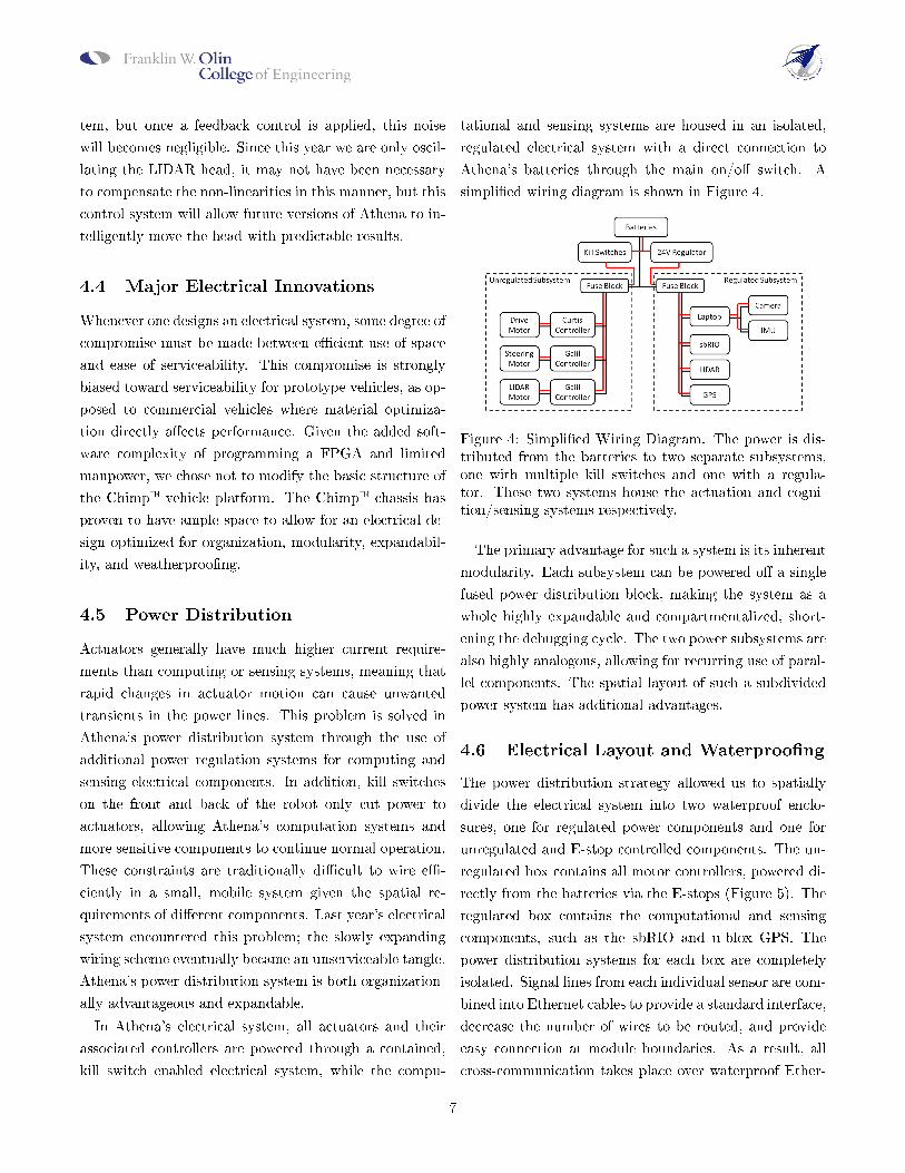
tational and sensing systems are housed in an isolated,
regulated electrical system with a direct connection to
Athena's batteries through the main on/o� switch. A
simpli�ed wiring diagram is shown in Figure 4.
Figure 4: Simpli�ed Wiring Diagram. The power is dis-tributed from the batteries to two separate subsystems,one with multiple kill switches and one with a regula-tor. These two systems house the actuation and cogni-tion/sensing systems respectively.
The primary advantage for such a system is its inherent
modularity. Each subsystem can be powered o� a single
fused power distribution block, making the system as a
whole highly expandable and compartmentalized, short-
ening the debugging cycle. The two power subsystems are
also highly analogous, allowing for recurring use of paral-
lel components. The spatial layout of such a subdivided
power system has additional advantages.
4.6 Electrical Layout and Waterproo�ng
The power distribution strategy allowed us to spatially
divide the electrical system into two waterproof enclo-
sures, one for regulated power components and one for
unregulated and E-stop controlled components. The un-
regulated box contains all motor controllers, powered di-
rectly from the batteries via the E-stops (Figure 5). The
regulated box contains the computational and sensing
components, such as the sbRIO and u-blox GPS. The
power distribution systems for each box are completely
isolated. Signal lines from each individual sensor are com-
bined into Ethernet cables to provide a standard interface,
decrease the number of wires to be routed, and provide
easy connection at module boundaries. As a result, all
cross-communication takes place over waterproof Ether-
7

net, FireWire, and serial cables, so no terminals are ex-
posed to the elements. The weather sensitive components
of the electrical system are thereby individually water-
proof, thereby avoiding the much more complex problem
of creating an entirely sealed vehicle chassis. The other
sensors not in the waterproof enclosures are spatially lo-
cated for optimal sensor range. These sensors are enclosed
in their own custom waterproo�ng enclosures.
Figure 5: Unregulated Power Electronics Box. This wa-terproof box, one of two boxes on the vehicle, houses theactuation electronics. Note the ease of service and roomfor expansion made possible by the organizational tech-nique.
5 Software Systems
5.1 Software Architecture
As discussed, Athena's computation is spread across three
di�erent processors: an FPGA, a real time processor, and
a PC. Each of these processing units performs a unique
role. Figure 6 shows a high level breakdown of software
modules. On the FPGA, there are several truly parallel
processes that parse and interpret the input data from
various high data rate sensors. These inputs are then
passed through a series of �nite state machines to create
a set of possible vehicle behaviors. The PC is used primar-
ily for image processing. Vision algorithms identify lines
for the purpose of avoidance and for destination genera-
tion. The PC also hosts the GPS because this low data
rate sensor has a National Instruments PC-hosted code
module. Finally, the RT processor selects the behavior
which optimally achieves the goal generated by the vision
processing. These operations will now be described in
greater detail.
Figure 6: Athena's Software Architecture. The diagramshows which behaviors and algorithms are hosted on whatprocessors.
5.2 FPGA-Hosted Computation
The FPGA hosted `software' performs three important
operations: sensor parsing, data transformation, and be-
havior generation.
5.2.1 Sensor Parsing
Each sensor's input stream is parsed with either a dis-
crete �nite automata (DFA) or a push down automata
(PDA), depending on the demands of the parser. Each
sensor input is not bu�ered. Instead, DFAs and PDAs
parse input strings byte by byte as they are acquired. An
example of a PDA modeled parser can be seen in Figure
7.
This PDA is used to recognize the two state
strings output by the VectorNav: a reset acknowl-
edge and a data stream. These strings take the
form of �$VNRRG,<x quaternion>,<y quaternion>,<z
quaternion>,<quaternion scalar>,<x acceleration>,<y
acceleration>,<z acceleration>,<x magnetic force>,<y
8

Figure 7: VectorNav Push Down Automata. Each tran-sition is labeled with a 2-tuple, where the �rst element isthe input that generates that transition and the second isthe character written to the stack (`' denotes no charac-ter being written). I is the input character and E is usedto denote a transition which is taken regardless of input.Unlabeled transition are taken if the input character doesnot match and labeled transitions.
magnetic force>,<z magnetic force>*<checksum>� or
�$VNRST*<checksum>� where each bracketed element
represents �xed point numeric data. Each time the PDA
enters the q12 accept state, a reset �ag is set acknowl-
edging the VectorNav's state. In order to read the data
passed to the FPGA in the VNRRG command once the
PDA enters the q8 state, the string that is received is
pushed onto the stack until that data element is done be-
ing input (as is indicated by the comma delimiter). Then,
when the PDA enters the q9 accept state, the stack is
�ushed and its data is written to a global variable which
corresponds to that data element. The correct data ele-
ment to write to is tracked by another DFA, which moni-
tors the parsing PDA's state. Each input is tracked with a
similar custom core that implements sensor output stream
parsing in hardware. Many of the resulting PDA and DFA
recognizers are much more complicated, but the same ba-
sic approach is applied.
While string parsing of sensor data streams is not usu-
ally detailed in robotic design reports, the approach de-
tailed above allows a few key advantages, and is thus
important. The use of PDA and DFA recognizers al-
low unbu�ered input to be parsed. As with later stages
of FPGA processing, Athena's sensor data acquisition is
done without the formation of intermediate representa-
tions. Instead, each character is immediately translated
into a meaningful representation. This speeds data pro-
cessing by eliminating overhead. These parsers are also
robust in the face of data loss.
5.2.2 Data Transformation
After the parsers recognize strings and turn them into
measurements, these measurements are then immediately
placed into Athena's local coordinate frame. This con-
verts LIDAR data into Cartesian inches centered about
the vehicle's LIDAR head, LIDAR tilt angle and steering
wheel angle into degrees, VectorNav heading into compass
degrees, and robot velocity in inches per second. Again,
this processing is done without bu�ering or intermediate
representations. Transformed data is then immediately
passed to the relevant behavior generation module.
5.2.3 Behavior Generation
Once data is parsed and transformed it is immediately
passed to parallel behavior generation modules. The pri-
mary behavior system is based on an obstacle and line
avoidance algorithm successfully implemented by Virgina
Tech's 2007 IGVC vehicle, Johnny-5 [5]. The algorithm,
summarized in Figure 8, examines 18 possible circular
paths corresponding to di�erent front wheel angle posi-
tions.
Figure 8: Drivable Paths Algorithm. The algorithm gen-erates a set of 18 possible behaviors in the form of a dis-tance driven along 18 arcs, corresponding to 18 possiblewheel angles.
Each path is then shortened to the length that can
9

be driven before an obstacle is encountered. In our im-
plementation of this algorithm, each time an obstacle is
identi�ed, its location is checked relative to each path.
If at any point along that path, the obstacle is closer
than a tunable passing distance, then the path is short-
ened to length where the path is no longer passable. This
algorithm is implemented on the FPGA using the state
machine shown in 9.
Figure 9: Behavior State Machine. The state machinewhich is used to generate a set of possible drive behaviors(ε transitions are taken regardless of sensor state deci-sion).
Data to update path lengths based on detected lines is
provided by a serial connection which directly connects
the FPGA to the PC. This connection transmits the lo-
cation of points which represent 3 inch squares deemed to
be the color of lines. Data for the obstacle path lengths
is provided by the output of the LIDAR data stream and
transform.
In order to update LIDAR scans at 70Hz, the FPGA
must be able to process the e�ect of a data point on each
of our 18 parallel paths 12,600 times per second. Each
path, in turn requires 112 inches of travel to be examined
for collisions. The necessary data rate is achieved by cre-
ating custom parallel processors to evaluate each path.
Both the line path evaluation and obstacle path evalua-
tion have their own cores, each of which have two parallel
path evaluation processors � one for left paths and one
for right paths.
Other behavior modules create robot motivation. An
�avoid explored areas� behavior tracks a trailing average
of vehicle position based of integration of VectorNav out-
put. This in turn gives a heading which corresponds to
the least explored area of the vehicle environment. An-
other useful motivating behavior is the �prefer constant
heading� behavior. This creates a trailing average of ve-
hicle heading. Both of these behaviors provide Athena
with a useful, lightweight representation of past vehicle
action which can be an accurate predictor of appropriate
future action.
All of these behavior modules are then fused using
a modi�ed subsumption architecture. Subsumption ar-
chitectures combine behavior modules like the ones de-
scribed above by layering behaviors into a hierarchy [1].
These behaviors are then blended using subsumption
functions. In our architecture, these functions are hosted
on the real time processor, and thus, will be discussed in
the real time processor section.
5.3 PC
The previous section discussed how data received from
sensors and PC based image processing is turned into a
set of potential robot behaviors. This section outlines
how image processing is implemented so that data can be
turned into behaviors. Additionally, this section outlines
how vision is used to create a goal for Athena. This goal
will later be used to judge the relative merit of the many
available behavior sets and combinations.
5.3.1 Vision Overview
The vision software on Athena follows the theme of modu-
lar design, adaptability, and optimization present in other
subsystems and software branches. Athena captures live
images using a Sony DFW-SX910 equipped with a Fuji-
non 3.4mm wide-angle lens mounted on the static sensor
mount of the vehicle. The live images are then trans-
formed onto a 2D plane in front of the robot and cor-
rected for nonlinear distortion (as de�ned by a previously
acquired calibration template). This transformed image
� ideally, an �overhead� view � is then made available
to a series of �lters which extract lines and/or obstacles.
The �lters include standard and adaptive RGB and HSL
10

Figure 10: Vision Processing Flowchart. A �owchart showing the vision processing algorithm from the image captureto goal extraction and obstacle identi�cation.
�lters, along with a pattern-matching �lter based on an
arti�cial neural network. The binary image results can
then put through a series of particle �lters to �lter for ob-
ject size and width. The �nal line-�ltered image is then
downsized, and the x and y coordinates of lines are passed
to the same FPGA-based obstacle avoidance and path-
planning algorithms used with LIDAR data. Finally, a
Hough transform is taken of the image data which allows
the robot to detect the presence and consistency of lines
and extract a goal from this. Figure 10 diagrams the
overall process.
5.3.2 Image Calibration
Image calibration allows us to remap pixels to real-world
coordinates. The calibration process analyzes a prere-
corded image of a grid of dots with a known spacing and
resizes the image such that the grid is spatially correct.
Given the information from this transformation, other im-
ages can also be corrected. We use this method to trans-
form the camera image to a top-down view, compensate
for the �sheye e�ects of wide-angle lenses, and �nd the
location of lines in real-world units. Figure 11 corrections
on the calibration template.
5.3.3 Filters
A wide array of image �lters have been created and imple-
mented on Athena. Because lighting conditions can vary
greatly between environments, each �lter can be selected
and tuned for a given test. Filters include basic RGB and
HSL �lters, adaptive versions of these �lters that account
for varying lighting conditions, and an arti�cial neural
network pattern-matching �lter. Particle �lters are then
Figure 11: Correcting For Nonlinear Distortion. Image a)shows a calibration image from the wide angle lens beforecorrection and b) shows the same image after transforma-tion.
applied to the binary images to reduce noise and extract
articles of interest. Line width and area �lters are par-
ticularly e�ective. The �nal �ltered image is then resized
to reduce the obstacle density, and the x, y coordinates
of the lines are passed to the FPGA using RS232. The
drivable paths algorithm is then run on this data to avoid
lines.
5.3.4 Goal Orientation
Once the solid lines have been �ltered out of an image,
a Hough transform is taken of the data to identify the
strongest lines. The slope of these lines, if deemed good
enough �ts, are used to determine the desired heading.
Because we are using a wide-angle lens, we can guarantee
that we will see past small gaps lines and will often see
both sides of the course. An e�ective Hough transform
can ensure that the desired heading remains correct even
when there are gaps in lines.
11

Figure 12: Vision Processing Example. Image a) showsthe raw camera output, b) shows the same image aftercalibration, c) shows the lines extracted with an adaptiveRGB and particle �lters, and d) shows the resized imagepassed to the FPGA to calculate drivable paths.
5.3.5 Navigation
Athena's localization and global navigation system is
composed of an u-blox series 5 GPS and a VectorNav-
100T Attitude and Heading Reference System (AHRS).
A low-accuracy localization unit, the u-blox GPS pro-
vides readings of a global position to within three meters
of the true location, at a rate of one reading per second.
At one hertz, the data rate is low enough to negate sim-
ple averaging as a method of increasing the accuracy of
global position measurements and improving global way-
point �nding and navigation.
Our solution to combating this de�ciency in localiza-
tion takes a macro to micro approach. We use the u-blox
GPS to guide Athena to the area roughly around a des-
ignated GPS target coordinate. Combining the current
GPS coordinates with a compass heading from the Vec-
torNav, our navigation algorithm provides Athena with
a preferable path upon which to drive to the target loca-
tion. Once in range, the control system ignores further
information from the GPS, and executes a circular search
pattern, reaching the target position at some point in
its path. To ensure that Athena does not wander from
the speci�ed search pattern, IMU measurements from the
VectorNav AHRS keep Athena aware of her position rel-
ative to the start of the search pattern. This allows us
to fully cover the area in which we know the target lo-
cation to be. Athena's navigation system is simple in
structure and implementation, but it provides a solution
to the problem of global waypoint �nding and navigation
using only low-cost sensors and simple algorithms.
5.4 Real Time Processor
As discussed in the previous section, data from the sensors
and the PC image processing is converted into a set of pos-
sible behaviors by the FPGA. These behaviors are then
organized into a subsumptive architecture. The subsump-
tion functions which allow these behaviors to interact are
hosted on the real time processor. In the original sub-
sumptive architecture proposed by Rodney Brooks layers
the set of behavior generating modules into a hierarchy.
The architecture then allows ranking behaviors to modify
the inputs and outputs of lower level behaviors. Tradi-
tionally, this override behavior is managed by a series of
static subsumption functions, which take in inputs from
ranking and subservient behaviors and allow the output
of the dominate behavior to choose how the inputs are
blended or overridden. This enforces a rigid hierarchy in
which each behavior is always either subservient or dom-
inate over another behavior. Athena uses the real time
processor to create a more �exible hierarchy.
Athena's subsumption functions blend �ve di�erent be-
haviors: avoid obstacles, avoid lines, move towards goal
point, prefer similar heading, and avoid explored areas.
In di�erent contexts, Athena's architecture will allow a
behavior to override the same behavior it submitted to
just moments ago. This is based o� of an assertiveness
asserted by each behavior. If the Hough transform of the
image processing has strong correlation, it will assert its
goal behavior more. Similarly, if there is a high standard
deviation to the prefer similar heading's trailing average,
it is less likely to assert dominance over other behaviors.
This �exible hierarchy allows us to leverage the advan-
tages of subsumption while also empowering very di�er-
ent behavior sets for the courses many contexts (solid
versus dashed lines or sparse versus dense obstacle envi-
ronments).
12

5.5 Software Innovation
We believe that the team's software strategy is novel
to the Intelligent Ground Vehicle's Competition. While
in the past other successful teams have used subsump-
tion to moderate between a smaller set of behaviors, [5]
we believe that no one has been able to implement be-
havior generation modules as truly parallel, independent
processes as we have on Athena's FPGA. In fact, with
the exception of an implementation of a three behavior
FPGA simulation done by researchers at Chulalongkorn
University [6] and a RC car controlled by a 256 gate pro-
grammable logic chip created by Rodney Brooks [4] it
appears as though this approach is relatively novel in the
greater robotics community.
However, innovation requires more than novelty; an in-
novative approach must be selected on a belief that it will
yield better outcomes. We believe that a reactive sub-
sumption behavior is in its own right well suited to the
IGVC. The inability to store prior knowledge means that
a robot's world models must be constructed while the ve-
hicle explores its environment. While not an intractably
hard problem, implementing SLAM on an IGVC vehicle
would prove very challenging. The high hardware cost
(both in sensors and computation) and extensive develop-
ment time to create a vehicle capable of constructing such
a world model again seems to indicate that an abstract
model based approach may not be appropriate. This is
particularly true given the relatively short distances trav-
eled by IGVC vehicles. This short distance means that
optimal path solutions yield little improvement from sim-
pler reactive navigation behaviors. However, just as we
must select the proper computational environment to run
algorithms, we also must select algorithms that are well
suited to our robot's environment.
This is the basis upon which our team was drawn to
subsumption. However, our software strategy does not
simply implement a previously postulated architecture.
It solves two key problems of subsumption by creating
truly parallel behavior modules and allowing for more
�exible blending of these modules. Even though sub-
sumption architectures were theorized as a composition
of parallel, �nite state machine modeled behaviors, this
was not how they were initially implemented. In prac-
tice, Rodney Brooks robots were frequently controlled by
single core Lisp machines which simulated �nite state ma-
chines [2]. Having to be tethered to a computer presents
obvious complications for the practical operation of such
robots. Not only does our software strategy break that
cord, it also enables behaviors to be implemented in par-
allel as true state machines. In addition to helping ad-
vance the theorized parallelism of subsumptive architec-
tures, our software allows for �exible adaptation to the
IGVC courses di�ering environments, rather than follow-
ing Brooks rigid architecture.
6 Performance
Athena is based on the Chimp� platform by Doran Elec-
tric Vehicles. This personal transportation vehicle (PTV)
is designed to carry a 300 pound rider at 11 mph on a �at
surface. The additional electric and mechanical systems
on Athena total less than 100 pounds. Therefore, we
expect performance well within the base vehicle's speci-
�cations. In our testing, we have never been limited by
the overall power and speed of the base vehicle.
Our 2009 competition entry, Brian, used the same base
platform and fared quite well in the Autonomous Chal-
lenge. It was, however, limited by its e�ective speed and
ability to distinguish gaps in lines. Through a better mo-
tor control algorithm and enhanced machine vision capa-
bilities, we were able to eliminate some of these downfalls.
At competition, Brian showed choppy motion and uneven
travel speeds that resulted in an average rate of 0.5 mph.
It also tended to oscillate between lines, a known lim-
itation of potential �eld algorithms in narrow corridors
[7]. Athena, on the other hand, has a more consistent
and �uid motion as de�ned by our drivable paths algo-
rithm. Initial tests show an average operating speed of
3 mph. We have also made several improvements to the
machine vision capabilities of our robot. Athena uses a
wide angle lens that provides a visible range of 25 ft and a
usable horizontal range of 30 ft. This allows us to always
have lines in view from which we can extract a desired
travel direction. This increased viewable area along with
our advanced �lters should allow us to quickly and easily
identify lines and desired paths through the course.
13

Brian (2009 entry) Athena (2010 entry)Metric Competition Performance Predicted Actual
Cognition Performance Metrics
Line Avoidance Reaction Time 0.1 s 0.067 s 0.067 sObstacle Avoidance Reaction Time 0.1 s 0.014 s 0.014 sLocalization Update Rate 2 Hz 50 Hz 50 Hz
Sensor Performance Metrics
LIDAR 2D Update Rate 10 Hz 70 Hz 70 HzLIDAR 3D Update Rate N/A 15 Hz 15 HzObstacle Detection Range 9 ft 22 ft 22 ftLine Detection Range 12 ft 23 ft 25 ftHeading Update Rate 2 Hz 50 Hz 50 HzGPS Watch Circle 3 m 3 m 3 m
Vehicle Performance Metrics
Top Speed 4.5 mph 4.5 mph 4.5 mphAverage Operating Speed 0.5 mph 3 mph 3 mphRamp Climbing Ability 15% grade 15% grade 15% gradeRunning Battery Life 1.8 h 1.8 h 1.9 hStandby Battery Life 10 h 14 h 16 h
Table 2: Performance Metrics
We also expect major improvements in the Navigation
Challenge. In 2009, we only reached a single waypoint due
to our inability to establish a reliable heading. Athena in-
corporates a new VectorNav Attitude Heading Reference
System that provides �ltered heading data for the robot.
With this information, we can now accurately calculate
our desired path to the waypoints.
Athena is capable of real-time obstacle avoidance,
meaning that it can avoid obstacles even in a dynamic
environment. The LIDAR can detect obstacles at a dis-
tance of 22 ft at a rate of 70 Hz. Because the course only
includes static obstacles, we have opted to take a 3D scan
of the environment by oscillating the LIDAR head. These
scans are accomplished at 15 Hz, which is still faster than
the update rate on our 2009 vehicle.
7 Conclusion
Athena represents a clear and already proven improve-
ment over the team's 2009 entry. Athena's novel use of
FPGAs and hardware abstraction has allowed the Olin
team to reduce Athena's line avoidance reaction time by
a third and the obstacle avoidance reaction time by an or-
der of magnitude. Higher processing speeds coupled with
LIDAR pitch control has more than doubled Athena's ef-
fective obstacle avoidance range to twenty two feet. Sim-
ilar improvements in lens selection and image processing
have increased the line detection range to twenty feet.
The result is a vehicle whose 3 mile per hour average
speed has far surpassed our original goal. We believe that
Athena's architectures also represent careful systems de-
sign, a innovative use of alternative computing fabrics,
and novel approach to the IGVC. However, the ultimate
proof of these methods will be her performance at com-
petition. The Olin College Ground Robotics Engineering
group proudly presents the college's 2010 IGVC entry,
Athena.
References
[1] Rodney A. Brooks. A Robust Layered Control System
for a Mobile Robot. IEEE Journal of Robotics and
Automation, RA-2, 1986.
[2] Rodney A. Brooks. A Hardware Retargetable Dis-
tributed Layered Architecture for Mobile Robot Con-
trol. In Proc. of the IEEE International Conference on
Robotics and Automation, pages pp. 106�110, Raleigh,
NC, 1987.
14

[3] Rodney A Brooks. Planning Is Just A Way Of Avoid-
ing Figuring Out What To Do Next. Cambridge, MA,
September 1987. MIT Arti�cial Intelligence Labora-
tory.
[4] Rodney A Brooks. Elephants Don't Play Chess. Cam-
bridge, MA, 1990. MIT Arti�cial Intelligence Labora-
tory.
[5] Andrew Fife, Jason Fountain, Andrew Livick, and Pe-
ter King. Virginia Tech Autonomous Vehicle Team
Presents: Johnny-5, 2007.
[6] Prabhas Kongmunvattana, Angkul; Chongstitvatana.
A FPGA-based Behavioral Control System for a Mo-
bile Robot. In IEEE Asia-Paci�c Conference on Cir-
cuits and Systems, Chiangmai, Thailand, 1998.
[7] Y. Koren and J. Borenstein. Potential Field Methods
and Their Inherent Limitations for Mobile Robot Nav-
igation. In Proc. of the IEEE International Confer-
ence on Robotics and Automation, pages 1398�1404,
Sacramento, California, 1991.
15