1. introduction and backgroundpceplume-700s1600e.net/documents/pdf/pdf_2017/03 2016 groundwa… ·...
TRANSCRIPT
2363 N. Hill Field Road, Suite 104 Layton, Utah 84041 Telephone: 385-393-4982 Fax: 801-779-0294
www.eaest.com
EN1204151012CVO 1
EA Engineering, Science, and Technology, Inc., PBC
TECHNICAL MEMORANDUM
TO: Lynne Welsh, Department of Veterans Affairs
FROM: Sandra Staigerwald, EA Engineering, Science, and Technology, Inc., PBC
DATE: April 20, 2016
SUBJECT: 2016 Monitoring and Supply Well Groundwater Sampling Plan for the 700 South 1600
East PCE Plume, Salt Lake City, Utah
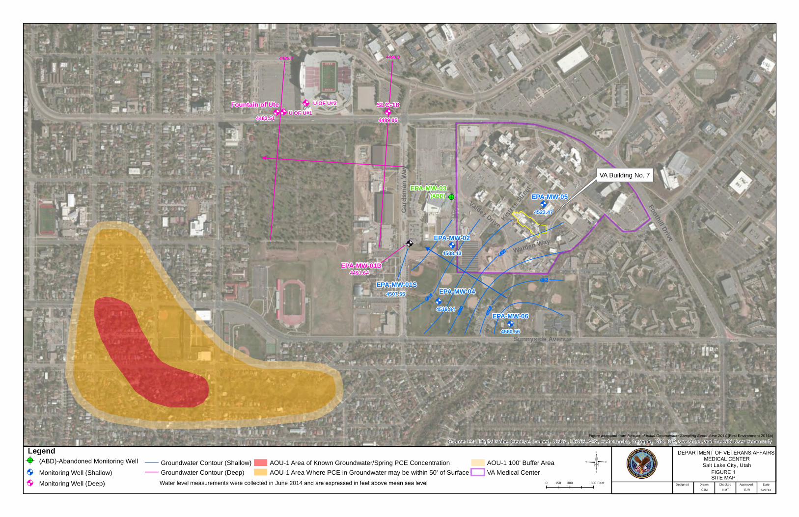
1. Introduction and Background This technical memorandum presents the 2016 monitoring well and supply well groundwater sampling plan for the 700 South 1600 East Tetrachloroethene (PCE) Plume. EA Engineering, Science, and Technology, Inc., PBC (EA), under contract number GS-10F-0228 (order number VA259-15-F-3886) to the U.S. Department of Veterans Affairs (VA) has prepared this plan to describe the proposed sampling of six existing monitoring wells and three existing water supply wells as a continuation of the groundwater sampling performed in 2014 (First Environment [FE] 2014b). The 2014 sampling was implemented in accordance with the Groundwater Sampling and Water Level Transducer Installation Scope of Work (FE 2014a). The data will be used to support the Operable Unit 2 (OU-2) Remedial Investigation (RI) of the 700 South 1600 East PCE Plume to be initiated in 2016, and an ongoing RI of Accelerated Operable Unit 1: East Side Springs (AOU-1), which is part of the 700 South 1600 East PCE Plume. Both RIs are being conducted by VA, which is working cooperatively with United States Environmental Protection Agency (EPA) and the Utah Department of Environmental Quality (UDEQ) to implement the OU-2 RI. The 700 South 1600 East PCE plume has not been fully investigated, but is assumed to originate from a dry cleaner that formerly operated out of Building 7 on the George E. Wahlen VA Medical Center (VAMC) located east of Guardsman Way and south of Foothills Drive in Salt Lake City, Salt Lake County, Utah. Based on results from the 2014 sampling event, groundwater direction appears to be to the northwest in shallow wells and to the west in the deeper wells (Figure 1). The plume underlies the neighborhoods surrounding the intersection of 700 South and 1600 East streets in Salt Lake City, Utah, a blended commercial and residential area of approximately 300 acres. AOU-1 is located along the Wasatch Fault scarp, west of the VAMC, within the general residential area bounded by 500 South and Michigan Avenue between 1300 East and 1100 East (Figure 1). Groundwater daylights in this area along the Wasatch Fault scarp as a series of seeps and springs. AOU-1 is defined as the area where springs are known to have PCE contamination and where groundwater is within 50 feet of the ground surface in the area of the Wasatch Fault scarp, including a 100-foot buffer around that area. PCE in groundwater in the area was first identified during routine monitoring of the Mt. Olivet Cemetery irrigation well conducted in 1990 by Salt Lake City Department of Public Utilities. In 1997, PCE was also detected in Salt Lake City municipal supply well No. 18 (SLC-18). Additional irrigation wells (e.g., the University of Utah Well #1) are also located along Foothill Drive in the vicinity of the plume. PCE has also been detected at parts per billion levels in surface water springs and in storm sewers within AOU-1. The EPA conducted a groundwater investigation in 1998 which included the installation of six groundwater monitoring wells – one on the VAMC campus, one to the south, and four to the west of the VAMC property (Figure 1). The activities described in this plan include sampling of the following
2363 N. Hill Field Road, Suite 104 Layton, Utah 84041 Telephone: 385-393-4982 Fax: 801-779-0294
www.eaest.com
EN1204151012CVO 2
EA Engineering, Science, and Technology, Inc., PBC
monitoring wells (MW-01S, MW-01D, MW-02, MW-04, MW-05 and MW-06), Mount Olivet Cemetery irrigation well, University of Utah Well #1, and SLC-18. The sampling will be performed in accordance with the Groundwater Sampling and Water Level Transducer Installation Scope of Work (FE 2014a). Applicable sections of the 2014 Plan are summarized below.
2. Coordination with Property Owners Prior to sampling, property access agreements will be obtained for sampling wells that are not located on
the VAMC campus. In addition, a request to allow sampling of the wells by VA will be submitted to the
EPA. It is anticipated that access agreements with Salt Lake City, the University of Utah, and the Mt.
Olivet Cemetery will be needed to collect groundwater samples from former public supply well SLC-18,
an existing University irrigation well, and the cemetery’s irrigation well, respectively. Monitoring wells
MW-01S, MW-01D, and MW-02 are located on the Salt Lake City Sports Complex property which is
part of Salt Lake County Parks and Recreation, a Division of the County's Department of Community
Services. Monitoring wells MW-04, and MW-06 are located in Sunnyside Park, a city park that is
operated and maintained by Salt Lake City Parks and Public Lands, a Division of the City Public Services
Department. MW-05 is located on VAMC property. Access to those wells not on the VAMC campus
will be coordinated with VA, EPA, and property owners prior to sampling. Contact information will be
obtained from VA representatives and attempts will be made to contact property owners, gain access
approval, and relay sampling schedules. The contractor shall give notice to the VA, EPA, and UDEQ
Remedial Project Managers two weeks in advance of groundwater sampling mobilization.
3. Groundwater Sampling
Groundwater sampling will be conducted in accordance with the protocols as described in the sections
below. The nine wells to be sampled include six existing monitoring wells (MW-01S, MW-01D, MW-
02, MW-04, MW-05, and MW-06) and three irrigation/production wells (SLC-18, University of Utah
Well #1, and Mt. Olivet Cemetery).
3.1 Removal of Transducers and Barometric Pressure Recorders Data from the Schlumberger Diver® water-level pressure transducers and barometric pressure recorders
that are currently deployed in wells MW-01S, MW-01D, MW-02, MW-04, MW-05, and MW-06 will be
downloaded to a computer prior to groundwater sampling and gauging in accordance with manufactures
instructions (see Sampling and Analysis Plan, 700 South 1600 East PCE Plume, AOU-1, Attachment 2
[FE 2014c]). Once the data has been downloaded, the transducers and their respective cables can be
removed from the well, wound up, and placed in a clean plastic bag or on clean plastic sheeting to prevent
contamination. Following groundwater sampling, the recorders will be re-suspended into their respective
monitoring wells and the data recordings will be resumed.
3.2 Groundwater Level Measurement Sampling personnel shall collect water-level measurements at the six existing permanent monitoring wells
prior to sampling. Depth to water will also be measured for the supply wells if there are no impediments
to placing the electronic water-level meter into the well. The depth to water will be recorded from the top
of the well casing or the existing specific surveyed reference point and the information will be recorded
on a well sampling form. Owners of the supply wells will asked if there is a survey point referenced to
2363 N. Hill Field Road, Suite 104 Layton, Utah 84041 Telephone: 385-393-4982 Fax: 801-779-0294
www.eaest.com
EN1204151012CVO 3
EA Engineering, Science, and Technology, Inc., PBC
mean sea level at the top of the well casing for measuring depth to water. If not, the height of the
reference point above ground survey will be measured in order to estimate the elevation of the reference
point. Well conditions (integrity of casing, cap, well accessories, etc.) will be visually inspected and
recorded on the sampling form along with the well diameter and reported total depth. The wells will be
sounded by lowering the water-level meter probe at least 50 to 100 feet into the water column to confirm
that the casing is not blocked or broken so as to prevent sample collection. Any wells not accessible to
gauging or sampling shall be noted on the sampling form.
3.3 Sampling of Groundwater Monitoring Wells and Inactive Supply Wells The existing monitoring wells shall be purged and sampled using an electric submersible pump
(Grundfos® or equivalent) and dedicated high-density polyethylene tubing. Samples will be collected
from the anticipated cleanest, i.e., least contaminated location, to the most contaminated location (i.e.,
MW-05, MW-06, MW-01D, MW-04, MW-02, MW-01S). This minimizes the opportunity for cross-
contamination to occur during sampling. The low-flow sampling technique recommended by the EPA
will be employed (EPA 1996; 2002). Low-flow purging will be conducted to remove stagnant water and
to allow infiltration of representative water from the aquifer into the well prior to sample collection. The
electric submersible pump with clean, dedicated tubing shall be lowered into the well until the pump
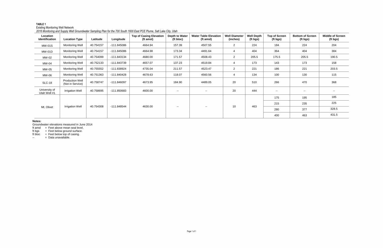
intake is placed within the screened interval (Table 1).
Once pumping has commenced, the pump rate will be maintained at less than or equal to 500
milliliters/minute. If water level drops, the pumping rate will be decreased until the water level stabilizes.
Effluent will be diverted to a flow-through cell attached to a water quality meter (Horiba, YSI, or
equivalent) to measure pH, specific conductance, oxygen-reduction potential, turbidity, dissolved oxygen,
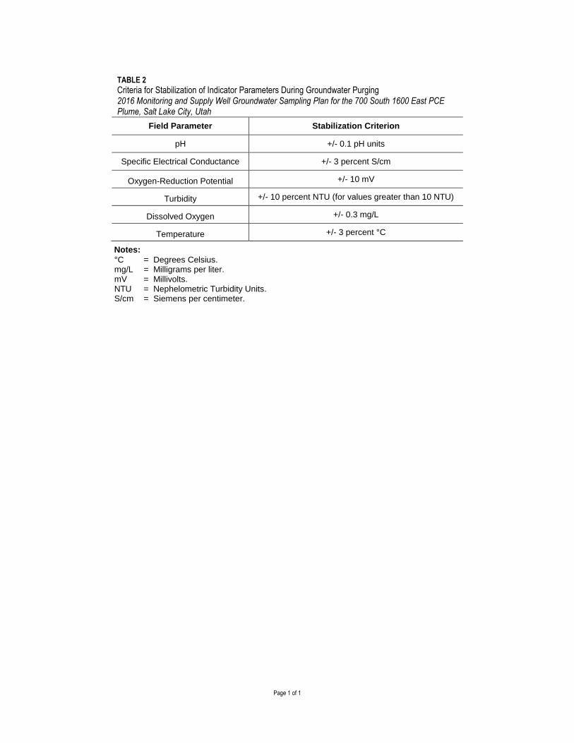
and temperature. Purging shall continue until field measurements have stabilized for at least three
consecutive readings as defined on Table 2. Since water quality parameter stabilization is the primary
criterion for sample collection by this method, if parameter stabilization is not occurring, the field team
leader may elect to collect the sample in consultation with VA.
Water quality field measurements will be collected and recorded on the sampling form at the start of
purging and at regular intervals during purging. Water-level measurements to determine the extent of
drawdown during purging will also be collected and recorded at regular intervals on the sampling form.
Pumping rate and total amount purged will also be recorded at the same frequency as water quality
measurements. The final water quality measurements shall be taken just prior to sampling and will serve
as the data for reporting purposes.
If supply wells (i.e. SLC-18, University of Utah Well #1, and the Mount Olivet Cemetery irrigation well)
are inactive or have no pumps, purging and sampling as described above will be attempted if there are no
impediments to deploying the pump into the well. If a pump is required for sampling the supply wells, a
rinsate blank will be collected prior to using the pump in the supply wells. The supply wells will also be
sampled in order from lowest to highest concentration (i.e. University of Utah Well #1, SLC-18, Mount
Olivet Cemetery irrigation well).
3.4 Sampling of Active Supply Wells
If supply wells have been pumping, this will suffice as purging. These wells will be sampled by
collecting the required volume of water from an access point located on the well discharge line as close as
possible to the wellhead. Should any supply well be inactive at the time of sampling and have a well head
2363 N. Hill Field Road, Suite 104 Layton, Utah 84041 Telephone: 385-393-4982 Fax: 801-779-0294
www.eaest.com
EN1204151012CVO 4
EA Engineering, Science, and Technology, Inc., PBC
that facilitates access by a bailer or small pump, samples will be collected to the extent possible,
regardless of the ability to complete a proper purge, so that data is obtained for the well. 3.5 Sample Collection Upon completion of purging at each well (except for the irrigation wells), groundwater samples shall be
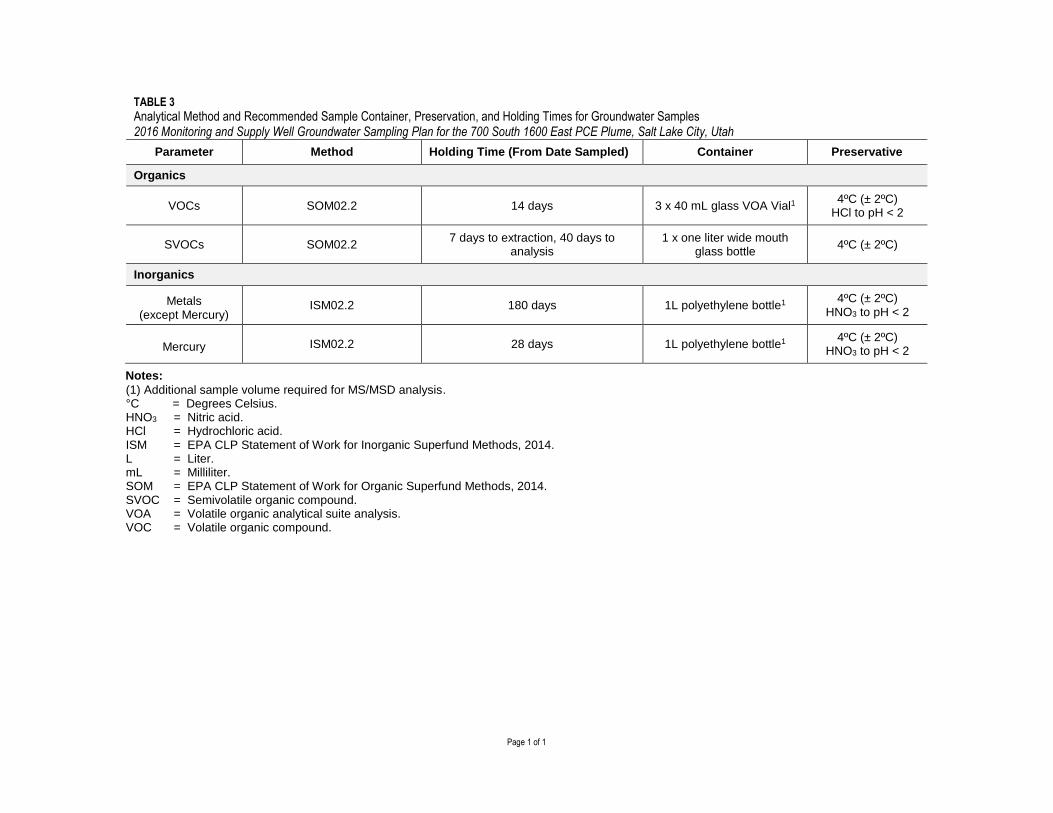
collected by detaching the effluent line from the flow through cell and filling the appropriate laboratory-
supplied bottles (Table 3) in a manner to minimize aeration of the sample. Samples for volatile organic
compounds (VOCs) will be collected first and samples for total and dissolved metals analyses will be
collected last. Any samples to be split between the consultant team and EPA or UDEQ will be collected
by alternately filling sample bottles for each party until all bottles for all analytes are filled. Sample
bottles shall be labeled with the well number, date, time of collection, and the required analyses. Upon
completion of sample collection, the bottles shall be packaged securely with plastic bags and bubble
wrap, placed on ice in a cooler, documented on a chain of custody, and shipped via overnight courier to
the laboratory.
3.5.1 Field and Laboratory Quality Control Samples Field quality control (QC) samples are collected to assess the field sampling procedures and include field
blanks (laboratory grade de-ionized water transferred from its original container to sample containers in
the field), equipment rinsate blanks (laboratory grade de-ionized water poured on or through sampling
equipment after decontamination), blind duplicate sample pairs (a second sample labeled to be
unidentifiable at the lab from a sampling point), and trip blanks (VOCs only – a set of filled sample
bottles supplied by the lab with the bottleware and remaining with the bottles and other samples during
the entire sampling event). Field blanks and equipment rinsate blanks will be collected at a minimum
frequency of one per 20 samples. Blind duplicate pairs will be collected at a minimum frequency of one
per 10 samples. Each cooler sent to the laboratory for analysis of VOCs will contain one trip blank.
Matrix spikes are designed to determine the precision and accuracy of the analysis. A minimum of one
matrix spike/matrix spike duplicate shall be designated for every 20 field samples, for applicable
methods. Samples identified for matrix spike/matrix spike duplicates will have triple the volume
collected (i.e. full sample volume for the normal sample, the matrix spike and the matrix spike duplicate).
3.6 Equipment Decontamination Equipment cleaning and decontamination is required for all re-usable equipment to be inserted into a well or that will come in contact with the groundwater, including: water-level indicators, water quality meters, and submersible pumps. The following procedures and cleaning protocol are to be followed in the field. Electronic water-level indicator probes/steel tape will be wiped with phosphate-free detergent and then thoroughly rinsed with distilled water. Due to the sensitivity of their probes, water quality meters and their associated flow-through cells will only be rinsed with distilled water between sampling locations. Upon completion of the groundwater sample collection, the submersible pump must be properly decontaminated between monitoring wells. Decontamination will be performed in accordance with the final Sampling and Analysis Plan for the 700 South and 1600 East PCE Plume (FE 2014c). Specifically decontamination procedure will consist of the following steps for the exterior surface and accessible interior surfaces of the pump: nonionic detergent wash; potable water rinse; distilled/deionized water rinse; air drying.
2363 N. Hill Field Road, Suite 104 Layton, Utah 84041 Telephone: 385-393-4982 Fax: 801-779-0294
www.eaest.com
EN1204151012CVO 5
EA Engineering, Science, and Technology, Inc., PBC
3.7 Analytical Program
Groundwater and quality assurance (QA)/QC samples will be submitted to a Contract Laboratory
Program (CLP) laboratory, to be selected by the EPA Region 8 Sample Coordinator prior to initiation of
well sampling. The EPA Superfund Analytical Services/CLP summary data packages will be required for
analyses performed at a CLP lab. They will contain sample results in accordance with instructions
provided in Section II, Exhibit B in the CLP statement of work (SOW) for inorganic analysis (EPA
2014a), and Section II, Exhibit B in the CLP SOW for organic analyses (EPA 2014b). All groundwater
and QA/QC samples, excluding trip blanks, will be analyzed for VOCs, semivolatile organic compounds,
and metals using the methods listed in Table 3. Trip blanks will be analyzed for VOCs only. Analytical
results will be reported to the lowest achievable method detection limits and reliable quantification levels.
Once results are received from the CLP laboratory, data will be validated in accordance with the Quality
Assurance Project Plan for East Side Springs (EA 2015) and provided to VAMC in electronic database
deliverable format.
4. Investigation Derived Wastes Groundwater purged from the monitoring wells and decontamination solutions shall be containerized at
the well locations in small transportable plastic containers, carried in field vehicles to a designated storage
location on the VAMC, and transferred into drums. The drums and transportable plastic containers will
be labeled as to the contents and waste type until sample analytical results indicate the appropriate
disposal option.
5. Site Control Only personnel assigned to the specific work tasks (or supervision of) will be permitted to enter the work
zones. As applicable, the Site Safety and Health Officer may delineate work zones by means of caution
tape, stakes, or traffic cones. Persons entering the work zone will be required to wear the appropriate
personal protective equipment and will only include those individuals employed with EA, VA or VA
designated contractors.
6. Documentation and Reporting The contractor will prepare a report summarizing the sampling event and the analytical results for submittal to the EPA Region 8 Remedial Project Manager. The report will include a summary of the field activities and analytical results.
7. Schedule Groundwater sampling from the existing monitoring wells will be performed following RI sampling
activities at AOU-1. The sampling is expected to commence in April 2016. Sampling of supply wells
may be postponed until later in April after the irrigation wells begin pumping for the season.
8. References EA Engineering, Science, and Technology, Inc., PBC. 2015. Quality Assurance Project Plan, 700 South
2363 N. Hill Field Road, Suite 104 Layton, Utah 84041 Telephone: 385-393-4982 Fax: 801-779-0294
www.eaest.com
EN1204151012CVO 6
EA Engineering, Science, and Technology, Inc., PBC
U.S. Environmental Protection Agency (EPA). 1996. Low-Flow (Minimal Drawdown) Ground-Water
Sampling Procedures. Office of Solid Waste and Emergency Response, EPA 540-S-95-504. April. EPA. 2002.Ground-Water Sampling Guidelines for Superfund and RCRA Project Managers. Office of
Solid Waste and Emergency Response, EPA 542-S-02-001. May. EPA. 2014a. SOW for Inorganic Superfund Methods, Multi-Media, Multi-Concentration. Document
Number ISM02.2. September. EPA. 2014b. SOW for Organic Superfund Methods, Multi-Media, Multi-Concentration. Document
Number SOM02.2. September. First Environment (FE). 2014a. Scope of Work – Ground Water Sampling and Water Level Transducer
Installation. May. FE. 2014b. Results of Initial Groundwater Sampling Event June 2014. September. FE. 2014 c. Sampling and Analysis Plan, 700 South and 1600 East PCE Plume, AOU-1: East Side
Springs, Salt Lake City, Utah. October.
2363 N. Hill Field Road, Suite 104 Layton, Utah 84041 Telephone: 385-393-4982 Fax: 801-779-0294
www.eaest.com
EN1204151012CVO 7
EA Engineering, Science, and Technology, Inc., PBC
Tables
1 Existing Monitoring Well Network
2 Criteria for Stabilization of Indicator Parameters During Groundwater Purging
3 Analytical Method and Recommended Sample Container, Preservation, and Holding Times for
Groundwater Samples
Figure
1 Site Map

Tables

THIS PAGE INTENTIONALLY LEFT BLANK
Page 1 of 1
TABLE 1
Existing Monitoring Well Network 2016 Monitoring and Supply Well Groundwater Sampling Plan for the 700 South 1600 East PCE Plume, Salt Lake City, Utah
Location Identification Location Type Latitude Longitude
Top of Casing Elevation (ft amsl)
Depth to Water (ft btoc)
Water Table Elevation (ft amsl)
Well Diameter (inches)
Well Depth (ft bgs)
Top of Screen (ft bgs)
Bottom of Screen (ft bgs)
Middle of Screen (ft bgs)
MW-01S Monitoring Well 40.754157 -111.845086 4664.94 157.39 4507.55 2 224 184 224 204
MW-01D Monitoring Well 40.754157 -111.845086 4664.98 173.34 4491.64 4 404 364 404 384
MW-02 Monitoring Well 40.754099 -111.843134 4680.00 171.57 4508.43 2 205.5 175.5 205.5 190.5
MW-04 Monitoring Well 40.752133 -111.843739 4657.07 137.23 4519.84 4 173 143 173 158
MW-05 Monitoring Well 40.755552 -111.838924 4735.04 211.57 4523.47 2 221 186 221 203.5
MW-06 Monitoring Well 40.751363 -111.840428 4678.63 118.07 4560.56 4 134 100 130 115
SLC-18 Production Well (Not in Service)
40.758747 -111.846097 4673.95 184.90 4489.05 20 510 266 470 368
University of Utah Well #1
Irrigation Well 40.758695 -111.850683 4600.00 -- -- 20 444 -- -- --
Mt. Olivet Irrigation Well 40.754308 -111.848544 4630.00 -- -- 10 463
175 195 185
215 235 225
280 377 328.5
400 463 431.5
Notes:
Groundwater elevations measured in June 2014 ft amsl = Feet above mean seal level. ft bgs = Feet below ground surface. ft btoc = Feet below top of casing. -- = Data unavailable.

THIS PAGE INTENTIONALLY LEFT BLANK
Page 1 of 1
TABLE 2
Criteria for Stabilization of Indicator Parameters During Groundwater Purging 2016 Monitoring and Supply Well Groundwater Sampling Plan for the 700 South 1600 East PCE Plume, Salt Lake City, Utah
Field Parameter Stabilization Criterion
pH +/- 0.1 pH units
Specific Electrical Conductance +/- 3 percent S/cm
Oxygen-Reduction Potential +/- 10 mV
Turbidity +/- 10 percent NTU (for values greater than 10 NTU)
Dissolved Oxygen +/- 0.3 mg/L
Temperature +/- 3 percent °C
Notes:
°C = Degrees Celsius. mg/L = Milligrams per liter. mV = Millivolts. NTU = Nephelometric Turbidity Units. S/cm = Siemens per centimeter.

THIS PAGE INTENTIONALLY LEFT BLANK
Page 1 of 1
TABLE 3
Analytical Method and Recommended Sample Container, Preservation, and Holding Times for Groundwater Samples 2016 Monitoring and Supply Well Groundwater Sampling Plan for the 700 South 1600 East PCE Plume, Salt Lake City, Utah
Parameter Method Holding Time (From Date Sampled) Container Preservative
Organics
VOCs SOM02.2 14 days 3 x 40 mL glass VOA Vial1 4ºC (± 2ºC)
HCl to pH < 2
SVOCs SOM02.2 7 days to extraction, 40 days to
analysis 1 x one liter wide mouth
glass bottle 4ºC (± 2ºC)
Inorganics
Metals (except Mercury)
ISM02.2 180 days 1L polyethylene bottle1 4ºC (± 2ºC)
HNO3 to pH < 2
Mercury ISM02.2 28 days 1L polyethylene bottle1 4ºC (± 2ºC)
HNO3 to pH < 2
Notes:
(1) Additional sample volume required for MS/MSD analysis. °C = Degrees Celsius. HNO3 = Nitric acid. HCl = Hydrochloric acid. ISM = EPA CLP Statement of Work for Inorganic Superfund Methods, 2014. L = Liter. mL = Milliliter. SOM = EPA CLP Statement of Work for Organic Superfund Methods, 2014. SVOC = Semivolatile organic compound. VOA = Volatile organic analytical suite analysis. VOC = Volatile organic compound.

THIS PAGE INTENTIONALLY LEFT BLANK

Figure

THIS PAGE INTENTIONALLY LEFT BLANK
@A
@A@A
@A
@A
@A @A
@A
@A
@A
@A @A
@A
@A
@A
@A
@A@A
@A
@A
!A
Gard
sman
Way
Sunnyside Avenue
Foothill Drive
Kisters
Street
Valdez Drive
Wahlen Way
4485.0 4490.0
@A
(ABD)
U OF U#1U OF U#2
EPA-MW-01D
SLC-18Fountain of Ute
EPA-MW-06
EPA-MW-05
EPA-MW-04
EPA-MW-03
EPA-MW-02
EPA-MW-01S
4560.56
4523.47
4519.84
4508.43
4507.55
4489.054483.51
4491.64
Source: Esri, DigitalGlobe, GeoEye, i-cubed, USDA, USGS, AEX, Getmapping, Aerogrid, IGN, IGP, swisstopo, and the GIS User Community
Legend!A (ABD)-Abandoned Monitoring Well
@A Monitoring Well (Shallow)
@A Monitoring Well (Deep)
Groundwater Contour (Shallow)
Groundwater Contour (Deep)
AOU-1 Area of Known Groundwater/Spring PCE Concentration
AOU-1 Area Where PCE in Groundwater may be within 50' of Surface
AOU-1 100' Buffer Area
VA Medical Center ©0 300 600150 Feet
5/27/14
Figure adapated from Results of Initial Groundwater Sampling Event June 2014 (First Environment 2014b)
DEPARTMENT OF VETERANS AFFAIRSMEDICAL CENTERSalt Lake City, Utah
FIGURE 1SITE MAP
CJM
Designed Drawn Checked Approved Date
NMT EJR
VA Building No. 7
Water level measurements were collected in June 2014 and are expressed in feet above mean sea level

THIS PAGE INTENTIONALLY LEFT BLANK