1. introduction to connections - nptel · 1. introduction to connections 1.1 overview: this lecture...
TRANSCRIPT

Course on Design of Steel StructuresProfessor Damodar Maity
Department of Civil EngineeringIndian Institute of Technology Kharagpur
Lecture 04Module 1
1. Introduction to Connections
1.1 Overview:
This lecture focused on the connections, which are essential to assemble the steel
sections/members to build a complete structure. Various connections are available for joining
members in case of RCC structure. Generally, we used to connect RCC members by casting
them in-situ. But in case of steel members different type of steel roll sections are available in
the market. The steel roll sections are need to join together and that can be done by applying
various types of connections, like rivet connections, bolt connections, weld connections and
combination of those two or three.
(Refer Slide Time: 1:07)
Generally, connection between two members are required at the following joints: beam and
column, main beam and secondary beam, column and column, column and brackets, column
and caps, Purlins and rafters, wind braces and columns, rail and columns. In case of truss
structure, truss members are connected through gussets that means when different members
are connected at a particular point then that can be connected through gussets member. So
when more than two members are joining at a point we need connections.
(Refer Slide Time: 2:15)

Further stiffeners in plate girders, diaphragms in plate girders, flange and web connections in
plate girders, stiffener plates in column joints are also used for connecting different type of
members. Methods of fabrication are basically three types: rivet joints, bolt joints and weld
joints. Also we can make combine of two or three of the above means in a particular joint we
can make use of rivet and bolt, bolt or weld, or bolt and rivet connection. So requirement
wise we have to choose an appropriate connection.
(Refer Slide Time: 2:58)
Now let us come to the requirement of good connection. What is good connection? Basically
good connection mean it should be such that it can easily be installed, inspected and
maintained, it should be such that there is the least possible weakening of the parts to be

joined and it should be rigid enough to avoid fluctuating stresses which may cause fatigue
failure.
1.2 Rivet connection:
(Refer Slide Time: 3:26)
Fig. 1 Rivet Connection
Now coming to rivet connections we know rivets are inserted in the plates to join together.
With different plates and by adding heat we can insert the. A typical rivet joint is shown in
Fig. 1, where different members are connected to plate by riveting and in the parts of rivet,
the upper part is called head and the lower cylindrical part is called shank. Shank has
particular length depending on the thickness of the plates, so it can vary accordingly.
Different type of heads is available and according to that different name of the defects are
given. Now this rivet head has a particular diameter which is called rivet head diameter and
the diameter of shank is called nominal diameter or rivet diameter or shank diameter.
Depending on the size of nominal diameter the strength of rivet can be calculated on the basis
of the type of material used and accordingly we can calculate the rivet strength.
(Refer Slide Time: 4:49)
Advantages of Riveted connections:
i. Ease of riveting process.
ii. Rivet connection is permanent in nature
iii. Cheaper fabrication cost.
iv. Low maintenance cost.
v. Dissimilar metals can also be joined; even non-metallic joints are possible withriveted joints.
vi. Rivet connection is possible without electricity in remote area
In case of welded connection, we need electricity otherwise it will be difficult to join the
members but in case of rivet connections, only through application of heat we can joined.
(Refer Slide Time: 5:59)
Disadvantages of Rivet Connection:
i. Necessity of pre-heating the rivets prior to driving
ii. Create high level of noise at the site of construction
iii. Skilled work necessary for inspection of connection
iv. Cost involved in careful inspection and removal of poorly installed rivets
v. High labor cost
So because of certain disadvantages nowadays riveting connections are becoming absolute,
mainly because of noise and because of generation of heat and difficulty to change the
improper insertion of the rivet.
(Refer Slide Time: 7:29)
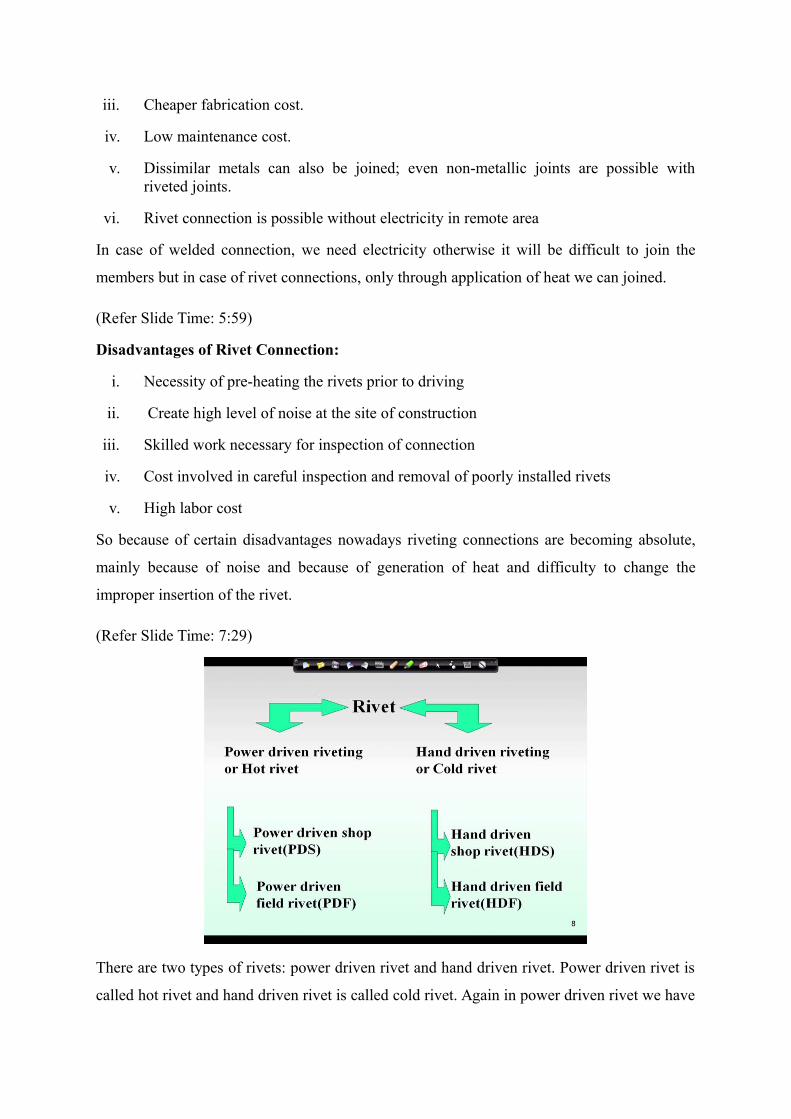
There are two types of rivets: power driven rivet and hand driven rivet. Power driven rivet is
called hot rivet and hand driven rivet is called cold rivet. Again in power driven rivet we have

two types, one is called power driven shop rivet and another is called power driven field rivet.
Similarly, for hand driven rivets, there are two types, hand driven shop rivet and hand driven
field rivets.
(Refer Slide Time: 8:02)
Now commonly used rivets are like snap head where the head dimensions are represented by
the shank diameter. If diameter of shank is d then we can consider that the diameter of rivet
head is 1.6d and the height of the rivet head is 0.7d. So with different height and diameter
different types of rivet heads are available. Two types of rivet are generally used as shown in
fig. 2.
Fig. 2 Commonly used rivet head
In case of flat head, the head diameter is 2d and head height is 0.25d and where d is the
nominal diameter of the rivet. The length of the shank is called rivet length. In this case we
should remember that there is two type of diameter, one is rivet diameter (nominal diameter)
another is hole diameter (gross diameter). Gross diameter is little higher than the rivet
diameter, and it is sometimes 1.5 or 2 mm more than the nominal diameter.
(Refer Slide Time: 9:33)
Now while designing the rivet joints we have certain assumptions we have to make, which
are as follows:
i. Friction between the plates is neglected.

ii. The shear stress is uniform on the cross section of the rivet.
iii. The distribution of direct stress on the portion of the plates between the rivet holes is
uniform.
iv. Rivets in group subjected to direct loads share the load equally.
v. Bending stress in the rivet is neglected.
vi. Rivets fill completely the holes in which they are driven
vii. Bearing stress distribution is uniform and contact area is d × t, where d is the nonal
diameter and t is the thickness of the plate.
As rivet connection is becoming absolute nowadays therefore in new code in IS:800-2007
details of rivet design is not given in Limit State Method however in case of bolt and weld
connection it has been described explicitly.
(Refer Slide Time: 11:51)
1.3 Bolt connection:
The design of bolt connection is generally done followed by IS 800-2007, where different
types of failure of bolt connections is consider and design accordingly. In clause 2.4 of IS:
800-2007 it says that bolts, nuts and washers shall conform as appropriate to the following
codes: IS 1363-1967, IS 1364-1967, IS 1367-1967, IS 3640-1967, IS 3757-1972, IS 6623-
1972 and IS 6639-1972. In those codes the bolt properties like their dimension, different
types, strength are given.

(a) (b) Fig. 3 A typical bolt connection and bolt
In fig 3a it is shown that different members are connected at a particular point using bolt
connection. Now If we come to the parts of bolts we can see bolt has a head, shank, runout,
thread and nut as shown in fig 3b. Nuts are generally tightened over the plate to connect
different plates at a particular point. The thread length, grip length, nominal length of the bolt
is also illustrated in fig. 3b.
So bolt has different parts like head, nut, shank, thread, thread length, grip length and
nominal length which will be required for our design. When we will be going for design of
different type of bolts we will see these parameters are required, these different dimension
like what is the nominal diameter of bolt, what is the gross diameter or hole diameter of bolt,
what is the type of head whether it is hexagonal or square, like this we will come across.
(Refer Slide Time: 14:34)

Now before going to use bolts we should know the advantages and disadvantages of bolts. As
I discussed earlier, there are three types of joints: bolt joint, rivet joint and weld joint, where
every joint has certain advantages and disadvantages. So we have to look what are the
advantages and disadvantages for a particular case where we are going to joining certain
member. Based on the type of connection design and the advantages and disadvantages, we
choose an appropriate connection.
Advantages of bolt connection:
i. Less manpower unlike rivet connection
ii. High strength bolts are much stronger than rivet. Hence, bolted connections need less
fasteners than rivet joints mean less holes in the plate resulting stronger connection.
iii. Bolting operation is much faster
iv. Bolting operation is very silent in contrast to hammering noise in riveting
v. Bolting is a cold process; no risk of fire
vi. Bolt can be removed, replaced or retightened easily in the event of faulty bolting or
damaged bolts due to accidents/hazards
(Refer Slide Time: 17:50)

Disadvantages of bolt connection:
i. Bolted connections have lesser strength in axial tension as the net area at the root of
the threads is less
ii. Under vibratory loads, the strength is reduced if the connections get loosened
iii. Unfinished bolts have lesser strength because of non-uniform diameter
iv. Architectural look
(Refer Slide Time: 19:41)
There are different types of bolts are available and these types are classified in different way.
According to material and strength we can classify this as ordinary structural bolt and high
strength steel bolt. But according to type of shank we can make three types of bolt:
unfinished or black bolt, turned bolt and high strength friction grip bolt (HSFG). This is very
important that high strength friction grip bolt is generally use in case of high load and if we
need less number of hole, less number of bolt then we have to go for HSFG bolt. According
to pitch and fit of thread three types of bolt can be categorized: standard pitch bolt, fine pitch
bolt and coarse pitch bolt. Then according to shape of head and nut we can make as square
bolt or hexagonal bolt. Square bolt means if the head of the bolt is square and hexagonal bolt
means if the head is hexagonal.
(Refer Slide Time: 21:11)

This is a typical example of hexagonal bolt. If we see here we will see that it has six number
of sides in this case.
(Refer Slide Time: 21:51)
Now we need to know some certain terminology before going to use design procedure of bolt
connections, like in case of rivet and bolt some terms are used like pitch distance, gauge
distance, edge distance, end distance, bolt hole, gross diameter, nominal diameter.
Two plates can be connected either by bolt or rivet connection. Now according to bolt
position there are various types of bolt connection, like regular bolting, zigzag bolting or
plane bolting or chain bolting, diamond bolting etc.

Fig 4. A typical bolt connection with regular bolting
The overlapping portion of the two plates as shown in the fig. 4, is called lap distance. Now
as you can see in fig. 4 that pitch is the center to center distance of adjacent bolt measure in
the direction of stress means the force direction. Similarly, the perpendicular to the direction
of stress, the center to center distance of adjacent bolt is called gauge distance. Parallel to the
direction of stress, the distance from the center of outermost bolt to the edge of the plate is
called end distance and perpendicular to the stress, the distance if we consider is called edge
distance.
Now the details of pitch distance and edge distance is discussed in clause 10.2.2 of IS 800-
2007 for particular connections. According to the code the minimum pitch distance is 2.5d or
2.5 times nominal diameter of the rivet or bolt. Why this minimum pitch is required because
we need sufficient space between this rivet or bolt to tightened so that it does not overlap. So
minimum pitch is required to tighten the bolts properly and to prevent the bearing failure
between two bolts if it is very closer than a bearing failure may occur, so to prevent this
bearing failure we need to specify a minimum pitch and code has specified this 2.5d.
Let us come to maximum pitch, what is maximum pitch and why that is necessary. Maximum
pitch is desirable to place bolt sufficiently close to reduce the length of connection and if we
have different members connecting at a point, we have more pitch distance than the gusset
plate will be require more. So the amount of material for gusset will be more that we do not
want, that is why we will try to make pitch distance as less as possible but not less than

minimum pitch. So this maximum pitch is defined in code which is written that the pitch
should be 16t or 200 mm in tension and it should be less than 12t or 200 mm in compression.
(Refer Slide Time: 28:32)
So while designing a member, say in case of a lap joint we need to provide bolts in such a
way that it follows the codal provision that means the limit of maximum pitch and minimum
pitch has to be maintained.
So minimum edge distance for rivet that is given 1.5d, where d is the nominal diameter of the
rivet, right and gross diameter as I told rivet has nominal diameter is termed as small d and
gross diameter which is the hole diameter actually in case of rivet that is termed as D and this
D will be d +1.5 for d is less than 25 mm and it will be d + 2 mm for d is greater than or equal
to 25 mm, which is given in IS 800: 1984 in the earlier code, in clause 3.6.1.1. When earlier
codes were available that means 1984 which was based on Working Stress Method at that
time the code has provided the gross diameter as nominal diameter plus 1.5 for nominal
diameter less than 25 and if it is more than 25 mm than it is d + 2, that means clearance has
been taken as 2 mm.
(Refer Slide Time: 32:25)

Now for bolt, in case of bolt the minimum and maximum edge distance and end distance are
given in clause 10.2.4.2 and 10.2.4.3. It is stated that the minimum edge or end distance that
should be greater than 1.7 times the hole diameter (dh) in case of sheared or hand-flame cut
edges and it should be greater than 1.5 times the hole diameter in case of rolled, machine-
flame cut, sawn and planed edges.
So for different cases the minimum edge distance is defined either 1.7 times the dh or 1.5
times dh and maximum edge distance, but it should be less than 12tε, where ε = (250/f y)1/2 and
t is thickness of the thinner part and maximum edge distance should not exceed this 12tε and
ε can be calculated from the steel property.
(Refer Slide Time: 34:39)

Now another term which we have already used that will come into discussion that is bolt
hole, which is required to fascinate the insertion of bolts to make the connection between
steel members and this bolt holes’ details are given in clause 10.2.1, table 19. The bolt holes
given in code depends on the diameter of the shank that means bolt diameter or nominal
diameter. If nominal diameter is 12 to 14 then standard clearance means hole will be 1 mm,
that means bolt hole is bolt diameter plus clearance of holes. You can refer to the code where
very meticulously this table has been described. Now for different cases this hole clearance
will be different, like for standard clearance it is 1 mm, for over size it is 3 mm, for short slot
it is (3 mm) 4 mm and for long slot it is 2.5 times d, where d is the diameter of the bolt.
Similarly, in case of bolt diameter from 16 to 22 this standard clearance is 2 mm, over size is
4 mm, short slot in case of that it is 6 mm and for all the cases it is 2.5d for long slot. Then
for 24 mm diameter of bolt the standard clearance is considered 2, over size is 6 and for short
slot it is 8 and for long slot 2.5d. If the diameter is greater than 24 mm then the standard
clearance is considered as 3 that means the whole diameter for standard is will be 24 + 3 that
is 27. Similarly, for over size it will be 8, for short slot it will be 10 and for long slot it will be
2.5d. So this is how the bolt hole will be calculated.