1 maintaining the design intent in the synthesis of 3d and...
TRANSCRIPT
1
Maintaining the Design Intent in the Synthesis of 3Dand 1D System Models using Constraints
Arquimedes Canedo1 Zhi Zhang2 Ahmad Albaqsami3 Student Member, IEEE, Jiang Wan4 Student Member, IEEE,and Mohammad Abdullah Al Faruque5 Member, IEEE,
Abstract—Systems design consists of both geometry-basedthree-dimensional (3D) and energy-based one-dimensional (1D)models. Automatically synthesizing 1D and 3D models from thesame specification is useful because it saves time and eliminateserrors. State-of-the-art synthesis algorithms use a one-to-onemapping of 3D to 1D artifacts and therefore only cover thegeometric aspects of the design. In this paper, we propose anapproach where constraints are abstracted to the functionallevel and integrated with the functional models thus providingfor efficient 3D to 1D mapping and allowing for 1D to 3Dmapping. Additionally, we present our work in the context ofProduct Lifecycle Management (PLM) systems and demonstratethe novel capabilities of our software using a real-world satelliteand excavator design examples.
I. INTRODUCTION
A single ship, airplane, or car design consists of thou-sands of high-fidelity models created using domain-specificmechanical engineering Computer-Aided Design (CAD) toolsthat contain precise information for manufacturing. Many ofthese geometric models are 3D in nature. Similarly, there areelectrical, software, control, and other models created withdomain-specific tools. Unfortunately, the high-level of special-ization and domain-dependency makes information exchangeamong these tools difficult. Currently, a technology growingin popularity is the so called 1D simulation. 1D simulationtools such as Modelica [1] and LMS Amesim [2] combinemultiple disciplines in a system-level model. This is possiblebecause the disciplines are integrated via energy conservationprinciples [3]. Using the 1D tools, an entire system can beanalyzed holistically using energy transformation and conser-vation principles.
An important problem is the automatic mapping between 3Dmodels and the equivalent 1D models. Although the manualcreation of one kind of model from another is possible, it istime consuming, error prone, and tedious. Several approacheshave been proposed to automatically generate 1D models from3D CAD information [4], [5], [6], [7] in a process referred to
1Arquimedes Canedo is with the Siemens Corporation, Corporate Technol-ogy, Princeton, NJ, USA.
2Zhi Zhang is with the Department of Computing and Information Sciences,Kansas State University, Manhattan, KS, 66502, USA.
3Ahmad Albaqsami is with the Department of Electrical Engineering andComputer Science, University of California, Irvine, CA, 92617, USA.
4Jiang Wan is with the Department of Electrical Engineering and ComputerScience, University of California, Irvine, CA, 92617, USA.
5Mohammad Abdullah Al Faruque is with the Department of ElectricalEngineering and Computer Science, University of California, Irvine, CA,92617, USA.
as “3D-to-1D” synthesis. These implementations exploit theredundancies in multibody systems to directly map bodies,joints, drivers, and parameters (e.g., mass, length, center ofinertia, forces) in 3D models to equivalent components andsome of their parameters in the 1D world. While obtainingthe equivalent mechanical structure automatically is a goodstarting point, the rest of the disciplines must be modeledmanually. A related problem is the creation of 3D models from1D models. This inverse process is much more complex thancreating 1D models from 3D models because there is less andoften orthogonal information in 1D models. Therefore, it isnecessary to include semantics in the process. To the best ofour knowledge, we are the first to demonstrate the automaticsynthesis of 3D models from 1D models in a process referredto as “1D-to-3D” synthesis.
In this paper, we introduce a constraint-based functionalmodeling approach to harmonize high-fidelity 3D and 1Dmodels. The key observation of our approach is that 3D and 1Dmodels created during the detail design phase have a commonorigin in functional models created earlier during the conceptdesign phase that capture the design intent explicitly. Besides,the universal constraint laws on the functional properties or pa-rameters apply to all models implementing the same functions.All these make it possible for us to express model constraintsand build model relationships at the functional level, whichcan be further enforced for automatic model generations. Forthe first time, we demonstrate that 3D-to-1D automatic modelgeneration can be extended beyond mechanical aspects and canbe contextualized to include other aspects such as electrical,thermal, and control. Functional information can be used toenhance 3D-to-1D model generation, and to synchronize high-fidelity models and maintain a consistent set of product infor-mation across tools and engineering disciplines. At the sametime, we demonstrate that the model constraint informationbuilt within functional models enables the automatic 1D-to-3D model generation. The novel contributions of this paperare as follows:• A new algorithm that significantly improves the capa-
bilities of automatic synthesis of 3D-to-1D models. Thekey innovation is the use of functional models duringsynthesis to infer the use of non-mechanical componentsinteracting with mechanical components.
• An extension to the functional models with a fully as-sociative constraint language for maintaining propertiesconsistent across models during their lifecycle.
• An implementation of the constraint solver that tracksthe changes to the instances of constraint variables, inter-

2
prets the constraints under new state, and finally updatesthe related models according to the new constraints state.
• An implementation of a workflow in PLM’s 3D and 1Dtools for users to create mappings of functions to 3Dartifacts, and the integration of this workflow with oursynthesis algorithm.
• The validation of our approach in a software prototypeand the synthesis of two real-world mechatronic exam-ples.
This paper is organized as follows. Section II provides thetechnical background and presents our contribution relative tothe related work. Section III presents our algorithm for 3D-to-1D synthesis and synchronization through the functionalmodels. Section IV defines our fully associative constraintlanguage and the constraint solver that is used for 1D-to-3D model synthesis and synchronization. Section V evaluatesour system in two real-world examples: a satellite, and anexcavator. Section VI provides our final remarks, and sets thedirection for future work.
II. BACKGROUND AND RELATED WORK
The tight integration of computation with multiple physicalelements in a system requires components to be designedand tested as part of a larger system (and not in isolation).Although system-level design tools such as Amesim [2],Matlab/Simulink [8], LabVIEW [9], and Modelica [1] arebeing integrated to PLM systems and adopted by industry,there are technical challenges that need to be addressed. Overthe years, many companies have accumulated knowledge andintellectual property in the form of high-fidelity 3D CADmodels that contain precise instructions for fabrication. Un-fortunately, 3D CAD models are not readily compatible withsystem-level design tools. This forces engineers to manuallyanalyze, abstract, and create new system-level models. This notonly increases the number of models to be maintained by thedomain experts but also presents the challenge of maintainingconsistency across models. Given that a single car, airplane,or ship consists of tens of thousands of 3D CAD models, itis critical to automate the process of mapping 3D to systemmodels, and vice versa, in order to help companies to leveragetheir accumulated corporate know-how.
The problem of 3D-to-1D synthesis has been the focus ofprior research. Several researchers have proposed tools thattranslate 3D CAD models to system-level models includingan Autodesk Mechanical Desktop to Modelica translator [4],a CATIA to Modelica translator [5], and generic 3D CADmodels to Matlab/Simulink/Simscape [10]. However, due tothe geometric nature of 3D CAD models, all these translatorsfocus exclusively on the extraction of geometric/mechanicaldata (e.g., dimensions, mass, center of inertia, orientation),kinematic data (e.g., rigid bodies and joints), and visualizationdata (e.g., geometry for rendering in STL file format [4]).Except for [5], all these translators are unidirectional becausethey allow 3D CAD to system-level generation but not theother way around – from system-level models to 3D CAD.In [5], bidirectional translation and model synchronization isrealized by associating system-level models with 3D CAD
models using a graphical user interface. An important aspectconsidered by the authors is the need to maintain a high designprocess efficiency in the presence of multiple engineers anddesigners in a PLM system. Compared to these tools, ourapproach is more flexible because it uses the design intentfor harmonization – rather than a GUI or brittle mapping rules– and it extends the synthesis beyond mechanical aspects.
We illustrate the limitations of the state-of-the-art tools withthe example of a satellite shown in Figure 1. The rules specifyhow 3D components map to 1D components; see how ¬, , ®,and ¯ in the 3D satellite model map to 1D Amesim model. Theremaining 1D components are sources and sinks that can alsobe specified as rules. Note that the synthesized 1D model is anequivalent mechanical representation of the 3D model. Furtherextending the model to other disciplines requires manual effort.
Fig. 1. Example of a direct 3D (left) to 1D (right) mapping without the useof a functional approach. The Satellite components are two solar panels (¬and ®), and joints ( and ¯).
The inverse process, i.e., 1D-to-3D, has not been exploredin the literature. One reason may be that 1D models, althoughmulti-disciplinary, provide less detail than 3D models. There-fore, this may be seen as a useless capability. However, ourwork shows that function-structure relationships can be en-coded in constraints and exploited by a PLM system to enable1D-to-3D synthesis of models while maintaining parameterconsistency.
Researchers in [11] have proposed the use of SysML to de-fine both models of possible components and possible systemarchitectures. Furthermore, they combine SysML/UML model-ing techniques with Open Modelica [12] simulation tool for aunified CPS modeling environment. The same researchers havedefined the SysML4Modelica model, which is an extensionof SysML, to model the system level requirements, behaviorsand constraints. They demonstrated that 1D Modelica modelscan be generated from the SysML4Modelica models [13]. Thelanguage ModelicaML [14] has very similar goals and hasdemonstrated similar capabilities.
The authors in [15] propose a design flow for CPS. It startswith using the SysML as a modeling language for specifyingsystem requirements and constraints by the developers. Then,a tool supports the automatic translation from SysML toAADL models for analysis. In [16], the authors investigatethe design of energy efficient buildings using SysML models.Design constraints are formally defined as design rules, whichuse the same syntax as modeling system functions in the

3
SysML models during the design time. Another relevant tool,the OpenMETA tool chain, integrates models and tools frommultiple domains into a single model integration languageCyPhyML. As a result, cross-domain design requirements andconstraints are formulated and can be evaluated and verifiedtogether [17]. While we are not the first to use constraintsto synchronize models, we are the first to use constraints incombination with functional models to harmonize 3D and 1Dtools.
A. Key Improvements Relative to Prior Art
Figure 2 summarizes the key improvements of our methodrelative to prior art. It also shows the newly introduced steps,both manual and automatic, and provides qualitative measuresof how the different design workflows are improved relativeto time (hours, minutes, seconds). Figure 2(a) shows threemodeling workflows that are possible with existing methods.The most common workflow starts by creating a 3D model(hours), mapping the 3D structures to 1D structures withhard coded rules, and automatically generating the 1D modelusing methods similar to [4], [5], [10]. The problem with thisapproach is the rigidity imposed by the hard-coded rules. Theother two workflows are less common but relevant to thispaper. One starts with an update to the automatically generated1D model (minutes), the propagation of changes to the 3Dmodel by an expert (minutes), and the update of the 3D model(minutes). The second workflow starts with an update to the3D model (minutes), the propagation of changes to the 1Dmodel by an expert (minutes), and the update of the 1D model(minutes). Note that these two workflows are entirely manualbecause it needs an expert who understands both the semanticsof the 1D and the 3D models. At best, these workflows takeseveral minutes every time there is a change.
Our method, as shown in Figure 2(b), introduces a fewmanual steps related to the creation of the functional model,and the mapping of functions to 3D structures. However, wedemonstrate that these new manual steps can be streamlinedvia a tool-specific implementation and in practice only take afew minutes to a few seconds to realize. Our first workflowrequires the manual creation of a functional model (see Sec-tion III) and constraints(See Section IV). After the 3D modelis created (hours), it also requires the manual association offunctions to 3D structures (see Section III.B) that typicallytakes a few minutes. The rest is automatic: constraints aresolved (seconds), and an equivalent 1D model is generatedby searching a database of compatible 1D components (seesynthesis algorithm in Section III.A). The major difference ofour method against existing methods is that functionality drivesthe synthesis process instead of having hard-coded rules.
Our second workflow shows the benefits of our functionalmodeling approach. A manual update on the 3D model can beautomatically propagated and updates the 1D model using theconstraint solving in just a few seconds. Our third workflowshows a novel capability where a manual update on the 1Dmodel is automatically propagated and updates the 3D modelusing the constraint solving in just a few seconds. These twoworkflows are experimentally demonstrated in Section V. Our
fourth workflow is expected to be less common, but changesto the constraints, rather than on either of the models areautomatically propagated via the constraint solving to the twomodels in just a few seconds.
In summary, our work introduces a few new manual steps,but is able to automate many of the processes required formodel harmonization. More importantly, it provides a moreintuitive approach for modeling based on functions, rather thanon tool-specific and domain-specific structures.
Fig. 2. Qualitative comparison of our approach versus the prior art.
III. FUNCTIONAL APPROACH OF 3D-TO-1D SYNTHESISAND SYNCHRONIZATION
Functional models describe the design intent – what thesystem does – in a multi-disciplinary yet implementation-independent manner [18], [19], [20], [21]. Functional modelsare a formal representation of requirements that engineersfrom different disciplines use to communicate effectively.This section presents how our approach leverages functionalmodels to improve the capabilities of 3D-to-1D synthesis, andits integration to a PLM workflow where different domainengineers can synchronize their designs using functions.
A functional model is a labeled directed graph F =(V,E, s, t, Lv, Le), where nodes vi, vj ∈ V , are connected byedges e(i,j) ∈ E. Each node vi is a function and each edgee(i,j) is a flow from function vi to function vj . s : E → Vand t : E → V are source and target mappings. l(v) ∈ Lv
and l(e) ∈ Le are unique labels, per v ∈ V and e ∈ E.
4
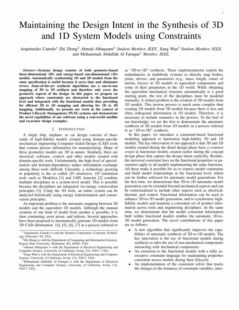
Figure 3 shows a satellite’s functional model consisting of19 labeled functions such as Store EE, Regulate RME,etc. In this paper, we use functional models stored as Visiodiagrams. This format allows users to rapidly generate dia-grams, functions, connections between functions, and to labelthe functional models. For elementary functions (e.g., Store,Convert) we use the Functional Basis language [21], and forhigher-level functions we use user-defined labels (e.g., AlignTelescope to the Sun). These functional models arethen parsed by C# code that extracts the topology and proper-ties needed as inputs to our algorithm. In this paper, we encodefunctional requirements R as constraints (see Section IV).Although it is out of the scope of this paper, an alternativeimplementation of functional models F and functional require-ments R could be implemented in SysML [22], [23], [24].
Fig. 3. Functional model of the satellite.
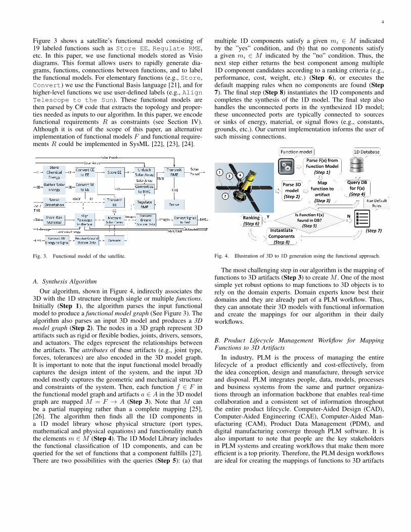
A. Synthesis AlgorithmOur algorithm, shown in Figure 4, indirectly associates the
3D with the 1D structure through single or multiple functions.Initially (Step 1), the algorithm parses the input functionalmodel to produce a functional model graph (See Figure 3). Thealgorithm also parses an input 3D model and produces a 3Dmodel graph (Step 2). The nodes in a 3D graph represent 3Dartifacts such as rigid or flexible bodies, joints, drivers, sensors,and actuators. The edges represent the relationships betweenthe artifacts. The attributes of these artifacts (e.g., joint type,forces, tolerances) are also encoded in the 3D model graph.It is important to note that the input functional model broadlycaptures the design intent of the system, and the input 3Dmodel mostly captures the geometric and mechanical structureand constraints of the system. Then, each function f ∈ F inthe functional model graph and artifacts a ∈ A in the 3D modelgraph are mapped M = F → A (Step 3). Note that M canbe a partial mapping rather than a complete mapping [25],[26]. The algorithm then finds all the 1D components ina 1D model library whose physical structure (port types,mathematical and physical equations) and functionality matchthe elements m ∈M (Step 4). The 1D Model Library includesthe functional classification of 1D components, and can bequeried for the set of functions that a component fulfills [27].There are two possibilities with the queries (Step 5): (a) that
multiple 1D components satisfy a given mi ∈ M indicatedby the ”yes” condition, and (b) that no components satisfya given mi ∈ M indicated by the ”no” condition. Thus, thenext step either returns the best component among multiple1D component candidates according to a ranking criteria (e.g.,performance, cost, weight, etc.) (Step 6), or executes thedefault mapping rules when no components are found (Step7). The final step (Step 8) instantiates the 1D components andcompletes the synthesis of the 1D model. The final step alsohandles the unconnected ports in the synthesized 1D model;these unconnected ports are typically connected to sourcesor sinks of energy, material, or signal flows (e.g., constants,grounds, etc.). Our current implementation informs the user ofsuch missing connections.
Fig. 4. Illustration of 3D to 1D generation using the functional approach.
The most challenging step in our algorithm is the mapping offunctions to 3D artifacts (Step 3) to create M . One of the mostsimple yet robust options to map functions to 3D objects is torely on the domain experts. Domain experts know best theirdomains and they are already part of a PLM workflow. Thus,they can annotate their 3D models with functional informationand create the mappings for our algorithm in their dailyworkflows.
B. Product Lifecycle Management Workflow for MappingFunctions to 3D Artifacts
In industry, PLM is the process of managing the entirelifecycle of a product efficiently and cost-effectively, fromthe idea conception, design and manufacture, through serviceand disposal. PLM integrates people, data, models, processesand business systems from the same and partner organiza-tions through an information backbone that enables real-timecollaboration and a consistent set of information throughoutthe entire product lifecycle. Computer-Aided Design (CAD),Computer-Aided Engineering (CAE), Computer-Aided Man-ufacturing (CAM), Product Data Management (PDM), anddigital manufacturing converge through PLM software. It isalso important to note that people are the key stakeholdersin PLM systems and creating workflows that make them moreefficient is a top priority. Therefore, the PLM design workflowsare ideal for creating the mappings of functions to 3D artifacts
5
that would be otherwise very difficult to create by algorithmicmeans.
In this paper we propose the use of functions as designcontracts between two or more PLM users that specify howtwo design elements relate to each other. In the PLM workflowcontext, functional models are formal requirements createdearly in the design; they capture the design intent of theentire system. Therefore, we leverage the system-level scopeof functions to propagate the design intent in 3D models.Establishing a design contract is a semi-automatic processbecause it requires two or more people first to agree, and thenthe PLM system automatically maintains this relationship.
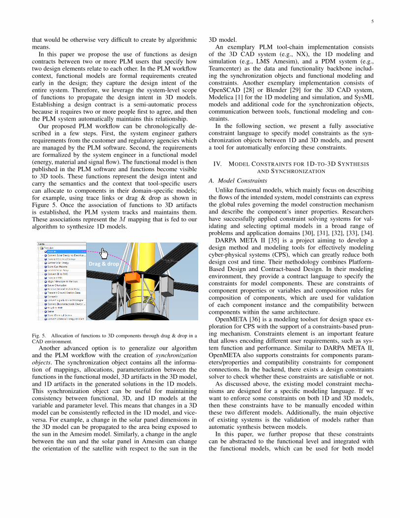
Our proposed PLM workflow can be chronologically de-scribed in a few steps. First, the system engineer gathersrequirements from the customer and regulatory agencies whichare managed by the PLM software. Second, the requirementsare formalized by the system engineer in a functional model(energy, material and signal flow). The functional model is thenpublished in the PLM software and functions become visibleto 3D tools. These functions represent the design intent andcarry the semantics and the context that tool-specific userscan allocate to components in their domain-specific models;for example, using trace links or drag & drop as shown inFigure 5. Once the association of functions to 3D artifactsis established, the PLM system tracks and maintains them.These associations represent the M mapping that is fed to ouralgorithm to synthesize 1D models.
Drag & drop
Fig. 5. Allocation of functions to 3D components through drag & drop in aCAD environment.
Another advanced option is to generalize our algorithmand the PLM workflow with the creation of synchronizationobjects. The synchronization object contains all the informa-tion of mappings, allocations, parameterization between thefunctions in the functional model, 3D artifacts in the 3D model,and 1D artifacts in the generated solutions in the 1D models.This synchronization object can be useful for maintainingconsistency between functional, 3D, and 1D models at thevariable and parameter level. This means that changes in a 3Dmodel can be consistently reflected in the 1D model, and vice-versa. For example, a change in the solar panel dimensions inthe 3D model can be propagated to the area being exposed tothe sun in the Amesim model. Similarly, a change in the anglebetween the sun and the solar panel in Amesim can changethe orientation of the satellite with respect to the sun in the
3D model.An exemplary PLM tool-chain implementation consists
of the 3D CAD system (e.g., NX), the 1D modeling andsimulation (e.g., LMS Amesim), and a PDM system (e.g.,Teamcenter) as the data and functionality backbone includ-ing the synchronization objects and functional modeling andconstraints. Another exemplary implementation consists ofOpenSCAD [28] or Blender [29] for the 3D CAD system,Modelica [1] for the 1D modeling and simulation, and SysMLmodels and additional code for the synchronization objects,communication between tools, functional modeling and con-straints.
In the following section, we present a fully associativeconstraint language to specify model constraints as the syn-chronization objects between 1D and 3D models, and presenta tool for automatically enforcing these constraints.
IV. MODEL CONSTRAINTS FOR 1D-TO-3D SYNTHESISAND SYNCHRONIZATION
A. Model ConstraintsUnlike functional models, which mainly focus on describing
the flows of the intended system, model constraints can expressthe global rules governing the model construction mechanismand describe the component’s inner properties. Researchershave successfully applied constraint solving systems for val-idating and selecting optimal models in a broad range ofproblems and application domains [30], [31], [32], [33], [34].
DARPA META II [35] is a project aiming to develop adesign method and modeling tools for effectively modelingcyber-physical systems (CPS), which can greatly reduce bothdesign cost and time. Their methodology combines Platform-Based Design and Contract-based Design. In their modelingenvironment, they provide a contract language to specify theconstraints for model components. These are constraints ofcomponent properties or variables and composition rules forcomposition of components, which are used for validationof each component instance and the compatibility betweencomponents within the same architecture.
OpenMETA [36] is a modeling toolset for design space ex-ploration for CPS with the support of a constraints-based prun-ing mechanism. Constraints element is an important featurethat allows encoding different user requirements, such as sys-tem function and performance. Similar to DARPA META II,OpenMETA also supports constraints for components param-eters/properties and compatibility constraints for componentconnections. In the backend, there exists a design constraintssolver to check whether these constraints are satisfiable or not.
As discussed above, the existing model constraint mecha-nisms are designed for a specific modeling language. If wewant to enforce some constraints on both 1D and 3D models,then these constraints have to be manually encoded withinthese two different models. Additionally, the main objectiveof existing systems is the validation of models rather thanautomatic synthesis between models.
In this paper, we further propose that these constraintscan be abstracted to the functional level and integrated withthe functional models, which can be used for both model
6
consistency checking and model synthesis. This is possible,because different models originate from the same functionintent, thus also obey the same constraints in general. Our ap-proach is to design a constraint language to not only specify themodel properties, but also constrain the dependencies betweenparameters of different models, which enables automatic modelreflection from one model to another once the association offunctions to structures is manually created (see Figure 2).
B. Overview
A functional model is a high-level system graph describingthe interactions between different function components. Foreach function component, it can be implemented with eitherone or more concrete model components. It makes sense thatany constraints on model components can be abstracted andlifted to the function components. So it’s natural to extend thefunctional model with the constraint mechanism by providingan option for adding constraints for each function component.
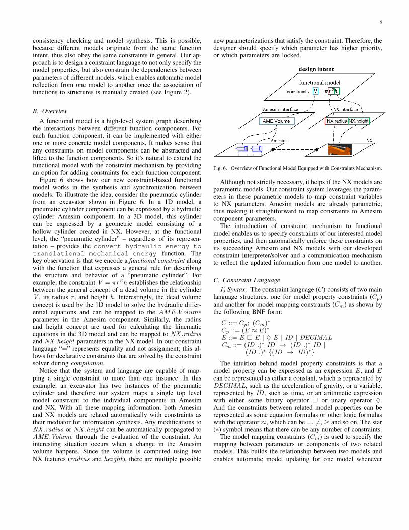
Figure 6 shows how our new constraint-based functionalmodel works in the synthesis and synchronization betweenmodels. To illustrate the idea, consider the pneumatic cylinderfrom an excavator shown in Figure 6. In a 1D model, apneumatic cylinder component can be expressed by a hydrauliccylinder Amesim component. In a 3D model, this cylindercan be expressed by a geometric model consisting of ahollow cylinder created in NX. However, at the functionallevel, the “pneumatic cylinder” – regardless of its represen-tation – provides the convert hydraulic energy totranslational mechanical energy function. Thekey observation is that we encode a functional constraint alongwith the function that expresses a general rule for describingthe structure and behavior of a “pneumatic cylinder”. Forexample, the constraint V = πr2h establishes the relationshipbetween the general concept of a dead volume in the cylinderV , its radius r , and height h . Interestingly, the dead volumeconcept is used by the 1D model to solve the hydraulic differ-ential equations and can be mapped to the AME.V olumeparameter in the Amesim component. Similarly, the radiusand height concept are used for calculating the kinematicequations in the 3D model and can be mapped to NX .radiusand NX .height parameters in the NX model. In our constraintlanguage “=” represents equality and not assignment; this al-lows for declarative constraints that are solved by the constraintsolver during compilation.
Notice that the system and language are capable of map-ping a single constraint to more than one instance. In thisexample, an excavator has two instances of the pneumaticcylinder and therefore our system maps a single top levelmodel constraint to the individual components in Amesimand NX. With all these mapping information, both Amesimand NX models are related automatically with constraints astheir mediator for information synthesis. Any modifications toNX .radius or NX .height can be automatically propagated toAME .Volume through the evaluation of the constraint. Aninteresting situation occurs when a change in the Amesimvolume happens. Since the volume is computed using twoNX features (radius and height), there are multiple possible
new parameterizations that satisfy the constraint. Therefore, thedesigner should specify which parameter has higher priority,or which parameters are locked.
Fig. 6. Overview of Functional Model Equipped with Constraints Mechanism.
Although not strictly necessary, it helps if the NX models areparametric models. Our constraint system leverages the param-eters in these parametric models to map constraint variablesto NX parameters. Amesim models are already parametric,thus making it straightforward to map constraints to Amesimcomponent parameters.
The introduction of constraint mechanism to functionalmodel enables us to specify constraints of our interested modelproperties, and then automatically enforce these constraints onits succeeding Amesim and NX models with our developedconstraint interpreter/solver and a communication mechanismto reflect the updated information from one model to another.
C. Constraint Language1) Syntax: The constraint language (C) consists of two main
language structures, one for model property constraints (Cp)and another for model mapping constraints (Cm) as shown bythe following BNF form:
C ::= Cp; (Cm)∗
Cp ::= (E ≈ E)∗
E ::= E � E | ♦ E | ID | DECIMALCm ::= (ID .)∗ ID → (ID .)∗ ID |
(ID .)∗ {(ID → ID)∗}The intuition behind model property constraints is that a
model property can be expressed as an expression E, and Ecan be represented as either a constant, which is represented byDECIMAL, such as the acceleration of gravity, or a variable,represented by ID , such as time, or an arithmetic expressionwith either some binary operator � or unary operator ♦.And the constraints between related model properties can berepresented as some equation formulas or other logic formulaswith the operator ≈, which can be =, 6=, ≥ and so on. The star(∗) symbol means that there can be any number of constraints.
The model mapping constraints (Cm) is used to specify themapping between parameters or components of two relatedmodels. This builds the relationship between two models andenables automatic model updating for one model whenever

7
changes happen to another. The variable ID is an identifierand can be quite flexible, it can denote model property, whichmeans mapping relationship between two different modelproperties, or it can denote model component, which meansmapping relationship between two different model compo-nents, or it can be extended to express tool-specific data.(ID .)∗ represents a prefix with dot . as separator and star∗ means it can repeat zero or more times.
The following section will present a concrete example thatshows how the constraint language looks like, and how it worksin constraining the model properties and building relationshipsbetween different models.
Fig. 7. Excavator Model in Amesim and NX.
2) Semantics: This section will give an informal semanticsfor constraint language through the excavator example shownin Figure 7, which shows its (a) Amesim model and (b) NXmodel.
Both Amesim and NX provide the parameter interface portsto expose internal parameters that are used in the internal repre-sentation of the abstract model components. In this example,the volume V , radius r, and height h are exposed throughparameter interfaces. These parameters can be connected toconstraint components, where each parameter becomes a vari-able to be used in a mathematical equation that describes aconstraint.
To make it simple, we take the component cylinder fromexcavator to illustrate the general ideas. The cyl2 on NXmodel corresponds to JACK02 in Amesim model and cyl3corresponds to JACK03 . For cylinder in NX, it has propertiesheight h and radius r, while in Amesim, JACK02 andJACK03 only have property volume V , but they are relatedwith the constraint: V = πr2h .
Figure 7 (c) shows the details of JACK and the cylinderthrough JACK02 and cly2 . JACK02 has two ports, port1and port2 , which have properties called dead1 and dead2 , thatcorrespond to the volume v in the constraint. Similarly, cly2also has two ports o1 and o2, but with two different properties{r1 , h1} and {r2 , h2}, corresponding to radius r and height
h in the constraint. Note that the port names port1 , port2 , o1and o2 can be any names as long as they are unique identifiersto distinguish different instances within the same component. Itis important for the constraint solver to have unique identifiers,because it avoids the ambiguity of the associated constraintsbetween two models.
( 1 ) V = πr2h;( 2 ) JACK02 .port1 .{V → dead1};
JACK02 .port2 .{V → dead2}( 3 ) cyl2 .o1 .{r → r1 , h → h1};
cyl2 .o2 .{r → r2 , h → h2}( 4 ) JACK02 .port1 → cyl2 .o1 ;
JACK02 .port2 → cyl2 .o2
The above statements specify constraints for JACK02and cly2 , where formula (1) specifies the model propertyconstraints, and mappings (2) (3) (4) give their mappingconstraints. Formula (1) is a global model constraint betweenconstraint variables, while mappings (2) and (3) are mappingconstraints between constraint variables and parameters ofcomponent instances in Amesim and NX. Mapping (2) speci-fies that JACK02 has subcomponents port1 and port2 , whichhave a volume property V . And V maps to dead1 and dead2 .Mapping (3) specifies that cyl2 has ports o1 and o2. o1 has aradius property r that maps to r1, and a height property h thatmaps to h1. Similar mappings are provided for o2. Mapping (4)provides the relationships between JACK02 and cyl2 , whereport1 is related to o1 and part2 is related to o2.
As we can see from this example, both Amesim model andNX model are regarded as two different instances of the samefunctional model, they share and comply with the constraintsdefined in the functional model, which makes it possible tokeep consistent between two different models by implementingappropriate constraint solver as discussed in the followingsection.
D. Constraint SolverThe user is in charge of writing the constraints. For example,
V = πr2h . During synthesis, these constraints are solved bya constraint solver and the values of the individual variablesare propagated to the components where they originate. Anadditional checking step may include validating whether thecomputed parameter from the constraint solving satisfies thelimits in the domain-specific representation of the component;for example, if the calculated volume does not exceed thebounds specified in the Amesim component.
To interpret the constraints automatically, we have imple-mented a constraint solver based on ANTLR parser genera-tor [37]. The constraint solver works in three steps:
1) parse the mapping constraints, build the mapping infor-mation for property constraints and the related designmodels, and stores the results in hash maps.
2) collect constraint-related properties information of boththe current working model and its associated models,which can be achieved by calling corresponding modelAPIs. For example, Amesim provides the Python Cir-cuit API to retrieve and update its model information,
8
and NX provides the C# NX Open API to performsimilar automation.
3) evaluate and solve the constraints by parsing the expres-sion Abstract Syntax Tree, fetching values accordingto the model properties, mapping the values to theconstraint equations, and solving the constraint system.For the current working model, a constraint is solvableiff all its constraint variables are computable. That is,the system of equations is fully determined. Cyclicdependencies are not allowed in the AST, and thereforethe complexity of evaluating the constraints is O(N),where N is the number of nodes in the AST.
An important use-case for the constraint solver is to com-municate constraint-related model information automaticallybetween Amesim and NX models. Figure 8 shows how thecommunication mechanism works among different modelsaccording to the specified constraints in the functional model.Ame-client is a client application built with the Circuit API,and it provides an interface for Amesim model to communicatewith the outside models. Similarly, NX-client is a client appli-cation built with NX Open API, and it provides an interfacefor NX model to communicate with the other models. Thecoordinator in the center will coordinate all communicationsbetween different model client applications and constraintsolver. If the user makes any changes to the properties of theNX model, the coordinator will call the NX-client to retrieveits updated information, and then pass this information tothe constraint solver to reevaluate the constraints. The newconstraint results are then pushed to the Ame-client, whichwill automatically enforce these new constraints accordingto the new updates in NX model. It is symmetric for theother direction (from Amesim to NX). This bidirectionalcommunication mechanism allows that any changes in onemodel are automatically reflected in another model. Usually,this is done manually by the user, and it becomes moredifficult if the Amesim model and NX model are developed bydifferent people. So this automatic communication mechanismcan greatly save human effort and make developers work moreefficiently.
Fig. 8. Constraint Solver for Model Information Synthesis.
V. EXPERIMENTAL RESULTS
The proposed system has been implemented in a C# proto-type. In this section we present the two key results for 3D-to-1D model generation, and for 1D-to-3D model generation. The3D-to-1D model generation can be qualitatively compared toexisting approaches. However, the 1D-to-3D model generationis a novel capability introduced by our work and thereforecannot be compared against other techniques.
A. 3D-to-1D Model Generation
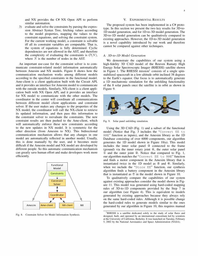
We demonstrate the capabilities of our system using ahigh-fidelity 3D CAD model of the Reuven Ramaty HighEnergy Solar Spectroscopic Imager (RHESSI) satellite shownin Figure 1. The RHESSI mission1 consists of a single spin-stabilized spacecraft in a low-altitude orbit inclined 38 degreesto the Earth’s equator. Our focus is to automatically generatea 1D mechatronic simulation for the unfolding functionalityof the 8 solar panels once the satellite is in orbit as shown inFigure 9.
Fig. 9. Solar panel unfolding simulation.
Using the 3D CAD (Fig. 1) and a subset of the functionalmodel (Notice that Fig. 3 includes the “Convert EE toRME” function as inputs), and the Amesim library as the 1DDatabase consisting of over 6000 components, our algorithmgenerates the 1D model shown in Figure 10(a). This modelincludes the inner solar panel ® connected to the frame(ground) via the inner rotary joint ¯, the outer solar panel¬ and the outer joint . Notice that compared to Fig. 1,our algorithm matches the “Convert EE to RME” functionand finds a motor component in the Amesim library that isinstantiated twice in the 1D model as ° and ±. Similarly,when we include the “Store EE” function, our synthesisalgorithm finds a battery component in the Amesim librarythat is instantiated as ² in the model shown in Figure 10.
To qualitatively compare the capabilities of our systemagainst existing approaches consider the model shown in Fig-ure 11. This model was generated using hard-coded mappingrules of 3D-to-1D components provided by the Step 7 inour algorithm (see Figure 4). This is equivalent to modelsgenerated by existing approaches because they always relyon the same hard-coded rules. Although it is possible changethe hard-coded rules to generate models similar to the onesgenerated by our algorithm in Figure 10, this requires manual
1RHESSI is a satellite dedicated solely to the study of solar flares anddesigned, built, and operated by an international consortium led by scientistsat the University of California, Berkeley. It was launched on Tuesday, February5, 2002 by the National Aeronautics and Space Administration (NASA).

9
Fig. 10. Example of a satellite’s functional model conversion of a) rotationalmechanical energy and b) stored electrical energy.
effort from experts and this can take several hours of error-prone labor. On the other hand, our algorithm can generatevarious models without changing any rules. This is becauseour algorithm relies on a search of equivalent components in3D and 1D databases using functions as queries. The mainbenefit of our approach to the end user is the ability toquickly generate models that include different design intents.Notice that the models in Figure 10 are complex in the sensethat multiple disciplines are combined and the design intentspecified by the user using functions is preserved.
Fig. 11. Model automatically generated using hard-coded rules.
B. 1D-to-3D Model GenerationTo verify the proposed method for model constraints, we
have implemented a prototype of the constraint solver basedon the solving procedure mentioned in Section IV. The goalis to illustrate a new capability of 1D-to-3D model generationon the excavator model shown in Figure 7.
Fig. 12. Example of an excavator’s 1D-to-3D Model Generation.
Figure 12 shows an example where changes in the excava-tor’s Amesim model (1D) are automatically synchronized inthe NX model (3D). The constraint expresses a synchronizationobject between Amesim’s “piston diameter” JACK02 .diampand NX’s piston diameter expressed by cyl2 .p0 . Initially, bothdiamp and p0 are 110mm and a new value of 210mm is set.After the change in Amesim, our system propagates the changeto the NX model and updates the model with the new diameter.Notice that the 3D model in Figure 12 shows a larger innerdiameter of the hydraulic piston.
VI. LIMITATIONS AND FUTURE WORK
In its present state, our prototype only works with 3D ge-ometric CAD models. 3D computer-aided engineering (CAE)models are not currently supported. However, it is importantto note that our approach is able to handle the CAE use-case because the constraint language can be easily adaptedto the constructs and variables in the CAE models. Similarly,our approach can be adapted to control models (e.g., Mat-lab/Simulink). We believe that a good direction of future workis the exploration of function-harmonized 3D CAE, 3D CAD,1D, and control models. This paper presents a step forwardtowards that vision.
Functional models are the enablers for our approach becausethey provide the unifying abstraction and semantics to harmo-nize 3D and 1D models. One limitation of existing design tools– not of our approach – is the lack or very limited supportfor functions. We believe it is necessary for the communityto better integrate functional modeling as part of the datamodels and interfaces of the system design tools. Withoutproper support of functional modeling in the system designtools, our approach would likely have a slow adoption.
10
Our current implementation still relies on the manual map-ping of functions to 3D structures. This manual step is alimitation that could be solved in the future. With access to alarge database of functional and 3D models, we envision thata machine learning algorithm could be trained to create thesefunction-to-3D mappings automatically. The biggest challengewill be obtaining a sufficiently large and representative dataset of functional and 3D models. The data sets are typicallysiloed in a company, and distributed across the organizationin different departments and teams. Collecting this data is agrand challenge.
VII. CONCLUSIONS
Automatic model generation and synchronization is signif-icant for both reducing manual effort and improving modeldesign procedures. In this paper, we explore a new wayto take it one step further in this direction by integratingconstraint-based functional model into the model generationprocedures. This paper shows that the quality (in terms of dis-ciplines and component variability) of automatically generated1D models from 3D models can be significantly improvedif functional information is considered. Our new synthesisalgorithm combines the information extracted from 3D modelsto design intent extracted from functional models, queriesfor 1D components fulfilling the desired functions in a 1Ddatabase, and instantiates the 1D components according to aranking function or default rules. Our results with a realisticmechatronic use-case show the feasibility of the idea anddemonstrate that design intent originally not available in the 3DCAD model can be carried over to the automatically generated1D models. On the other hand, the model constraints provide aconstruct for different models and enable the synchronizationof 3D models with respect to the updated 1D models. Theconsistency between 1D and 3D models can therefore beautomatically enforced once the association of functions tostructures is manually established.
REFERENCES
[1] “Modelica association, modelica standard library.” [Online]. Available:https://modelica.org/libraries/Modelica/
[2] “LMS Imagine.Lab AMESim.” [Online]. Available: http://www.plm.automation.siemens.com
[3] W. Borutzky, Bond graph methodology: development and analysis ofmultidisciplinary dynamic system models. Springer Science & BusinessMedia, 2009.
[4] P. Bunus, V. Engelson, and P. Fritzson, “Mechanical models translation,simulation and visualization in modelica,” in Visualization in Modelica.Proc. of Modelica 2000 Workshop, 2000, pp. 199–208.
[5] P. Bhattacharya, N. S. Welakwe, R. Makanaboyina, and A. Chi-malakonda, “Integration of catia with modelica,” in proceedings ofModelica conference, 2006.
[6] D. Baumgartner, A. Pfeiffer, J. Brembeck, A. Pfeiffer, M. Fleps-Dezasse, M. Otter, K. Wernersson, and H. Elmqvist, “Automatedmodelica package generation of parameterized multibody systems incatia.”
[7] C. C. Hilding Elmqvist, Sven Erik Mattsson, “Redundancies in Multi-body Systems and Automatic Coupling of CATIA and Modelica,” inProceedings of the7th Modelica Conference, 2009, pp. 551–560.
[8] “Simulink.” [Online]. Available: http://www.mathworks.com/products/simulink/
[9] “Labview system design software.” [Online]. Available: http://www.ni.com/labview/
[10] A. Mukherjee, V. Chudnovsky, J. Wendlandt, and N. E. Brewton,“Translating of geometric models into block diagram models,” Sep. 102013, uS Patent 8,532,966.
[11] A. A. Kerzhner and C. J. Paredis, “Using domain specific languagesto capture design synthesis knowledge for model-based systems engi-neering,” in ASME 2009 International Design Engineering TechnicalConferences and Computers and Information in Engineering Confer-ence, 2009, pp. 1399–1409.
[12] “Open Modelica.” [Online]. Available: https://www.openmodelica.org/
[13] A. Reichwein, C. J. Paredis, A. Canedo, P. Witschel, P. E. Stelzig,A. Votintseva, and R. Wasgint, “Maintaining consistency betweensystem architecture and dynamic system models with sysml4modelica,”in Proceedings of the 6th International Workshop on Multi-ParadigmModeling. ACM, 2012, pp. 43–48.
[14] W. Schamai, P. Fritzson, C. Paredis, and A. Pop, “Towards uni-fied system modeling and simulation with modelicaml: modeling ofexecutable behavior using graphical notations,” in Proceedings 7thModelica Conference, Como, Italy, 2009, pp. 612–621.
[15] D. Cofer, A. Gacek, S. Miller, M. W. Whalen, B. LaValley, and L. Sha,“Compositional verification of architectural models,” in NASA FormalMethods. Springer, 2012, pp. 126–140.
[16] T. Kurpick, C. Pinkernell, M. Look, and B. Rumpe, “Modeling cyber-physical systems: model-driven specification of energy efficient build-ings,” in Proceedings of the Modelling of the Physical World Workshop.ACM, 2012, p. 2.
[17] J. Sztipanovits, T. Bapty, S. Neema, L. Howard, and E. Jackson,“Openmeta: a model-and component-based design tool chain for cyber-physical systems,” in From Programs to Systems. The Systems perspec-tive in Computing. Springer, 2014, pp. 235–248.
[18] M. Erden, H. Komoto, T. van Beek, V. D’Amelio, E. Echavarria,and T. Tomiyama, “A review of function modeling: Approaches andapplications,” Artificial Intelligence for Engineering Design, Analysisand Manufacturing, vol. 22, pp. 147–169, 3 2008.
[19] A. Canedo, J. Wan, and M. Al Faruque, “Functional modeling com-piler for system-level design of automotive cyber-physical systems,”in Computer-Aided Design (ICCAD), 2014 IEEE/ACM InternationalConference on, 2014, pp. 39–46.
[20] A. Canedo, E. Schwarzenbach, and M. Al Faruque, “Context-sensitivesynthesis of executable functional models of cyber-physical systems,”in Cyber-Physical Systems (ICCPS), 2013 ACM/IEEE InternationalConference on, 2013, pp. 99–108.
[21] J. Hirtz, R. B. Stone, D. A. McAdams, S. Szykman, and K. L. Wood,“A functional basis for engineering design: reconciling and evolvingprevious efforts,” Research in engineering Design, vol. 13, no. 2, pp.65–82, 2002.
[22] “OMG Systems Modeling Language (SysML).” [Online]. Available:http://http://www.omgsysml.org/
[23] J. Lamm and T. Weilkiens, “Funktionale architekturen in sysml,” Tagdes Systems Engineering, pp. 109–118, 2010.
[24] B. Kruse, T. Gilz, K. Shea, and M. Eigner, “Systematic comparisonof functional models in sysml for design library evaluation,” Procedia{CIRP}, vol. 21, pp. 34 – 39, 2014, 24th {CIRP} Design Conference.
[25] J. Wan, A. Canedo, and M. Al Faruque, “Functional model-based designmethodology for automotive cyber-physical systems,” Systems Journal,IEEE, vol. PP, no. 99, pp. 1–12, 2015.
[26] J. Wan, A. Canedo, and M. Al Faruque, “Cyber-physical codesign at thefunctional level for multidomain automotive systems,” Systems Journal,IEEE, vol. PP, no. 99, pp. 1–11, 2015.
[27] A. Canedo and J. H. Richter, “Extraction of system functions from 1-dsimulation component libraries,” in Proceedings of the 6th International

11
Workshop on Equation-Based Object-Oriented Modeling Languagesand Tools, ser. EOOLT ’14. ACM, 2014, pp. 83–91.
[28] “OpenSCAD.” [Online]. Available: http://www.openscad.org/[29] “Blender.” [Online]. Available: https://www.blender.org/[30] I. P. Gent, C. Jefferson, and I. Miguel, “Minion: A fast scalable con-
straint solver,” in ECAI 2006, 17th European Conference on ArtificialIntelligence, 2006, pp. 98–102.
[31] S. Gulwani, S. Srivastava, and R. Venkatesan, “Program analysis asconstraint solving,” Microsoft Research, Tech. Rep. MSR-TR-2008-44,March 2008.
[32] D. Jackson and M. Vaziri, “Finding bugs with a constraint solver,” inISSTA, 2000, pp. 14–25.
[33] L. M. de Moura and N. Bjørner, “Z3: an efficient SMT solver,” inTools and Algorithms for the Construction and Analysis of Systems,14th International Conference, TACAS 2008, 2008, pp. 337–340.
[34] C. Barrett, C. L. Conway, M. Deters, L. Hadarean, D. Jovanovic,T. King, A. Reynolds, and C. Tinelli, “CVC4,” in Computer AidedVerification - 23rd International Conference, CAV 2011, Snowbird, UT,USA, July 14-20, 2011. Proceedings, 2011, pp. 171–177.
[35] B. T. Murray, A. Pinto, R. Skelding, O. de Weck, H. Zhu, S. Nair,N. Shougarian, K. Sinha, S. Bopardikar, and L. Zeidner, “Meta iicomplex systems design and analysis (coda),” 2011.
[36] J. Sztipanovits, T. Bapty, S. Neema, L. Howard, and E. K. Jackson,“Openmeta: A model- and component-based design tool chain forcyber-physical systems,” in From Programs to Systems. The Systemsperspective in Computing - ETAPS Workshop, FPS 2014, 2014, pp.235–248.
[37] “ANTLR - ANother Tool for Language Recognition.” [Online].Available: http://www.antlr.org/