1 moment area theorems: when a beam is subjected to external loading, it under goes deformation....
TRANSCRIPT
1
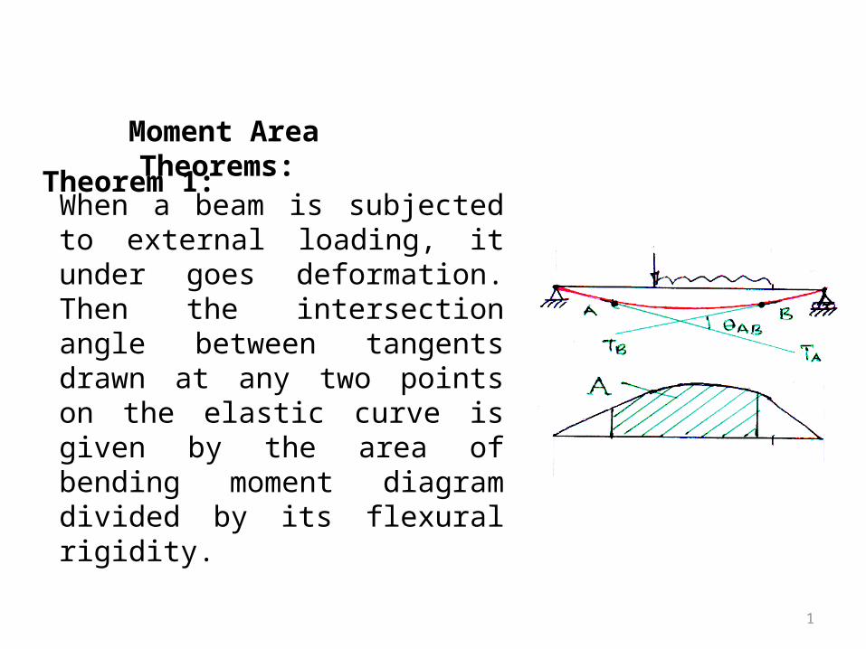
Moment Area Theorems:
When a beam is subjected to external loading, it under goes deformation. Then the intersection angle between tangents drawn at any two points on the elastic curve is given by the area of bending moment diagram divided by its flexural rigidity.
Theorem 1:
2
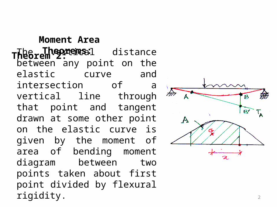
Moment Area Theorems:
The vertical distance between any point on the elastic curve and intersection of a vertical line through that point and tangent drawn at some other point on the elastic curve is given by the moment of area of bending moment diagram between two points taken about first point divided by flexural rigidity.
Theorem 2:
3
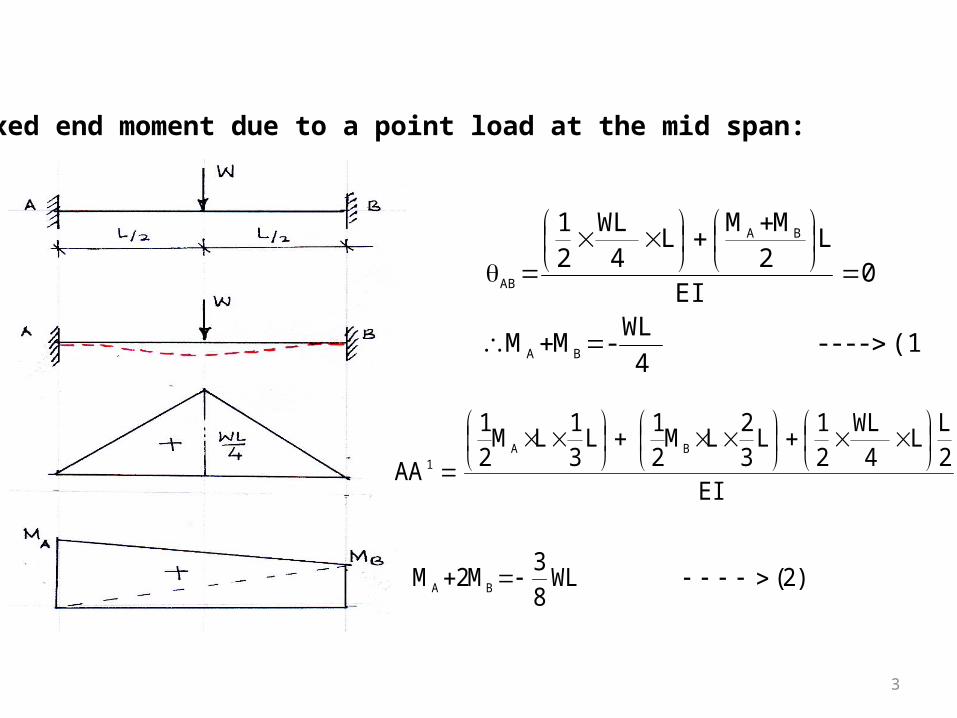
Fixed end moment due to a point load at the mid span:
(1) ----4
WL - MM
0EI
L2
MML
4WL
21
BA
BA
AB
)2(WL8
3M2M
EI
2L
L4
WL21
L32
LM21
L31
LM21
AA
BA
BA1

4
Both moments are negative and hence they produce hogging bending moment.
8
WL
8
WL
4
WLM
4
WLM
8
WL M
get we(2) and (1) From
BA
B

5
Stiffness coefficients
a) When far end is simply supported
EI
MomentBB
Babout B &A between BMD of area of '
EI3
ML
EI
L 32
L M 21
2
EI3
ML LBB
2
A I
A L
EI3 M
6
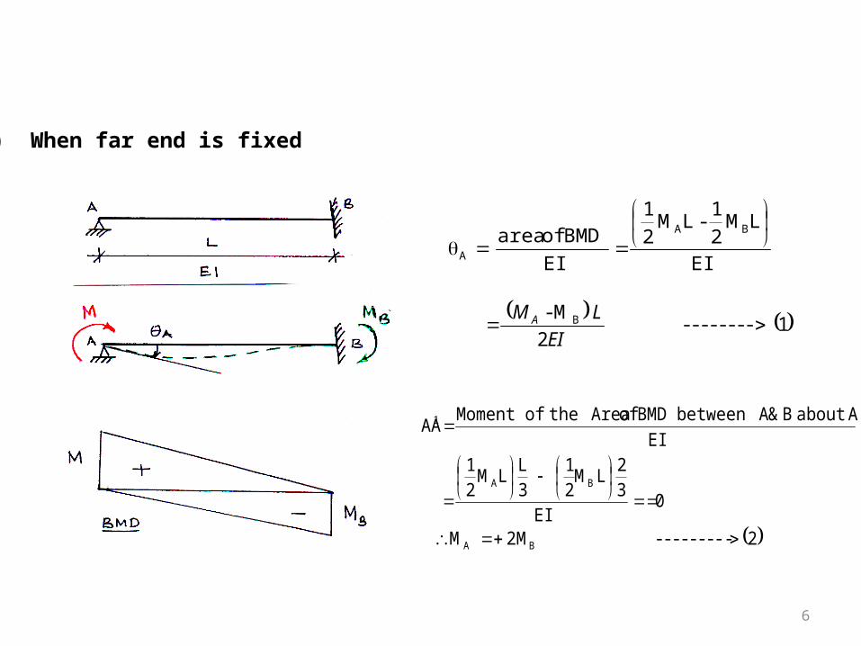
b) When far end is fixed
EI
LM2
1 - LM
2
1
EI
BMD of area
BA
A
1 -------- 2
M - B
EI
LM A
2--------- 2M M
0EI
32
LM21
3L
LM21
EI
Aabout B & A between BMD of Areathe of Moment AA
BA
BA
1

7
Substituting in (1)
AB
ABB
ABA
L
2EI M
EI2
LM - M2
EI2
LMM
ABA L
4EI M 2 M )2(From
8
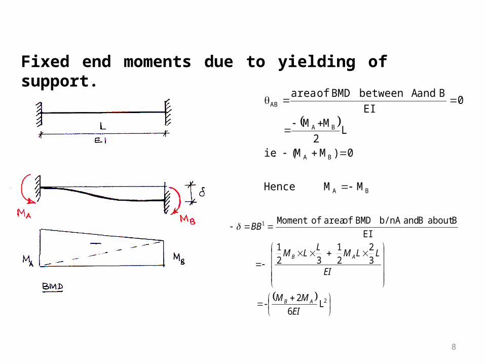
Fixed end moments due to yielding of support.
M M Hence
0)MM(.ie
L2
MM
0EI
B and A between BMD of area
BA
BA
BA
AB
2
1
L 6
2 -
3
2
2
1
32
1
EI
Babout B andA b/n BMD of area ofMoment
EI
MM
EI
LLML
LM
BB
AB
AB
9
26
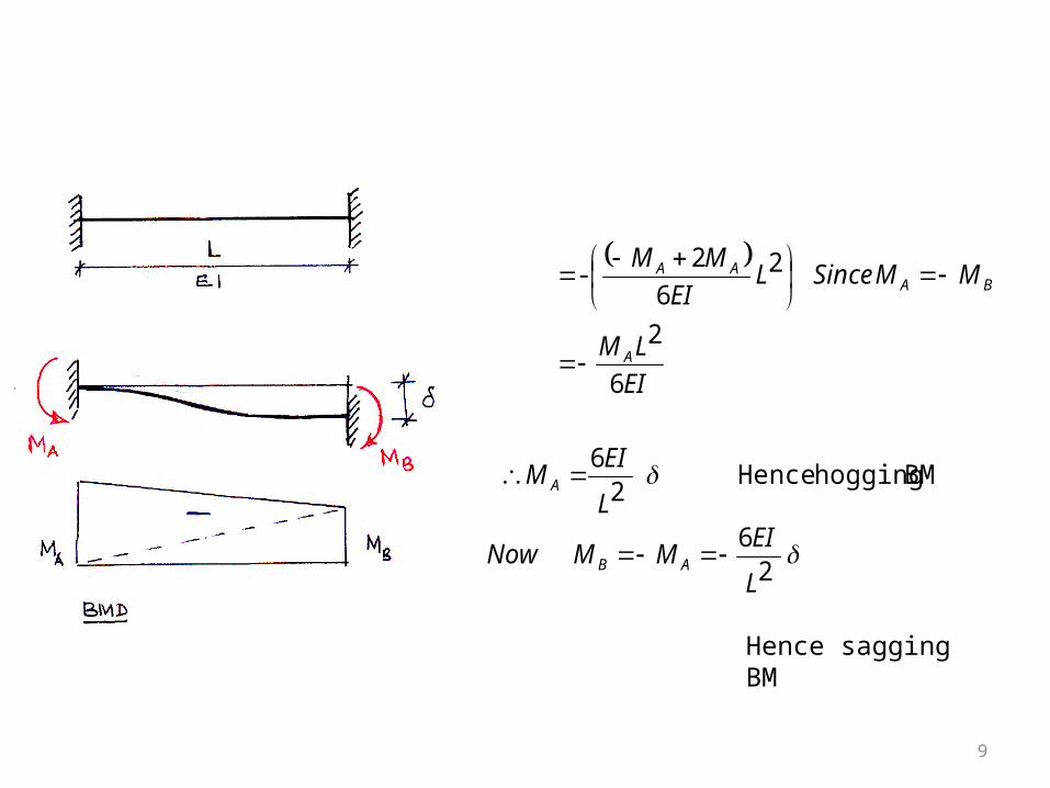
BM hogging Hence 2
6
6
2
26
2-
L
EIMMNow
L
EIM
EI
LM
MMSinceLEI
MM
AB
A
A
BAAA
Hence sagging BM
10
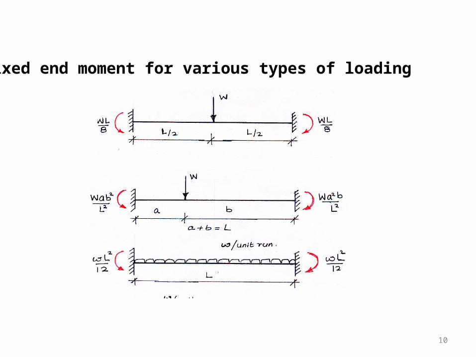
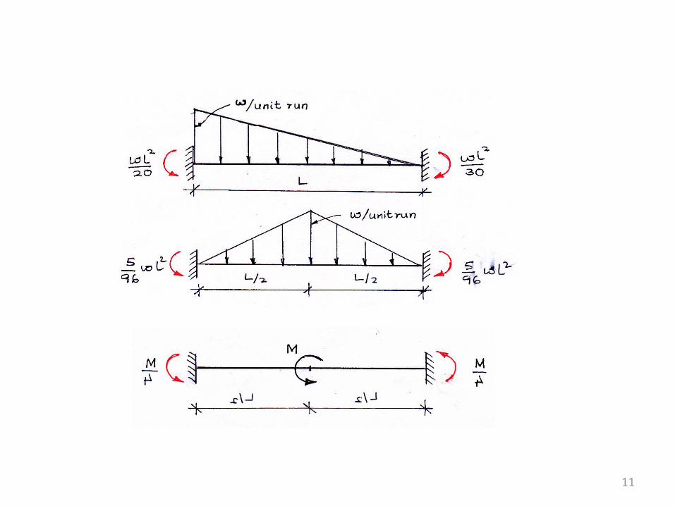
Fixed end moment for various types of loading
11
12
Assumptions made in slope deflection method:
1) All joints of the frame are rigid
2) Distortions due to axial loads, shear stresses being small are neglected.
3) When beams or frames are deflected the rigid joints are considered to rotate as a whole.
13
Sign conventions:
Moments: All the clockwise moments at the ends of members are taken as positive.
Rotations: Clockwise rotations of a tangent drawn on to an elastic curve at any joint is taken as positive.
Sinking of support: When right support sinks with respect to left support, the end moments will be anticlockwise and are taken as negative.
14
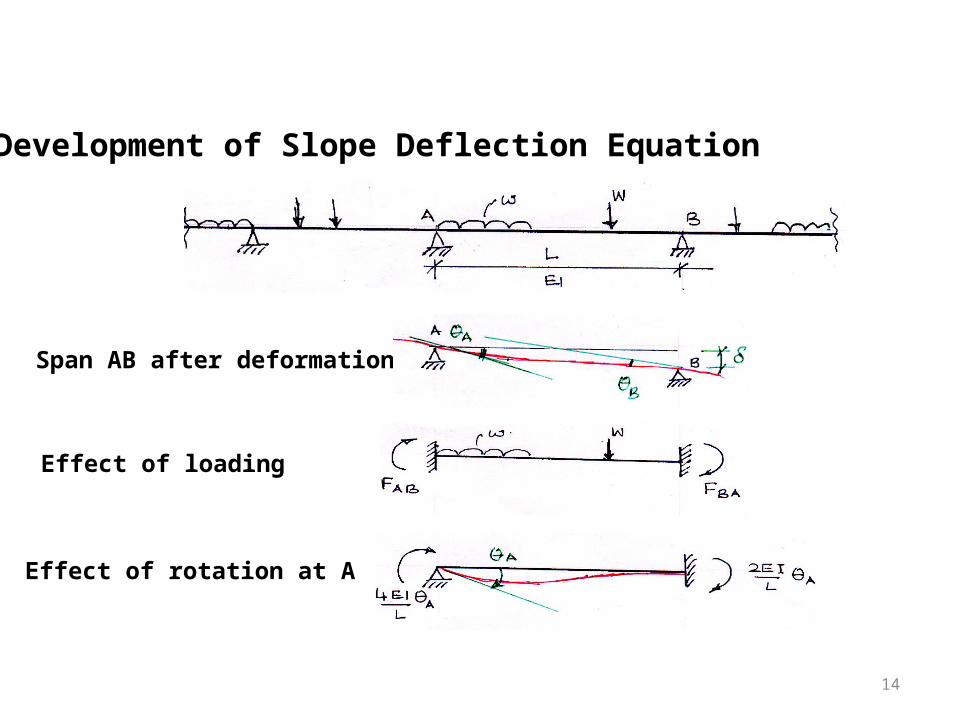
Development of Slope Deflection Equation
Span AB after deformation
Effect of loading
Effect of rotation at A
15
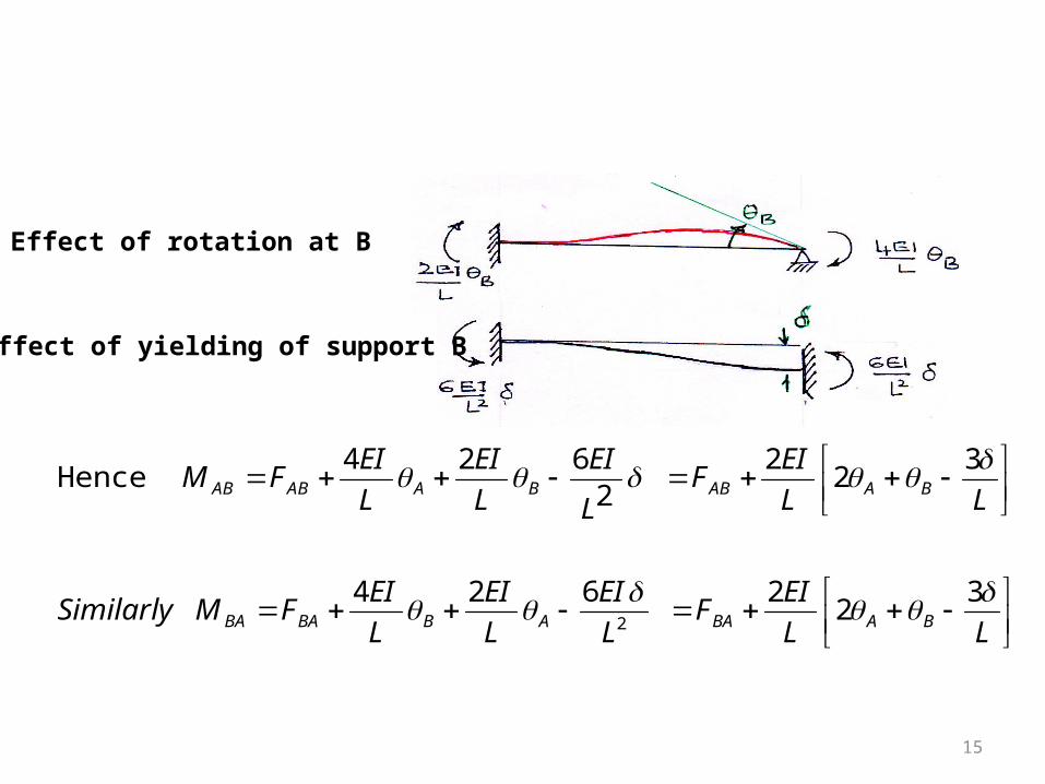
Effect of rotation at B
Effect of yielding of support B
LL
EIF
L
EI
L
EI
L
EIFMSimilarly
LL
EIF
L
EI
L
EI
L
EIFM
BABAABBABA
BAABBAABAB
32
2624
32
22
624Hence
2
16
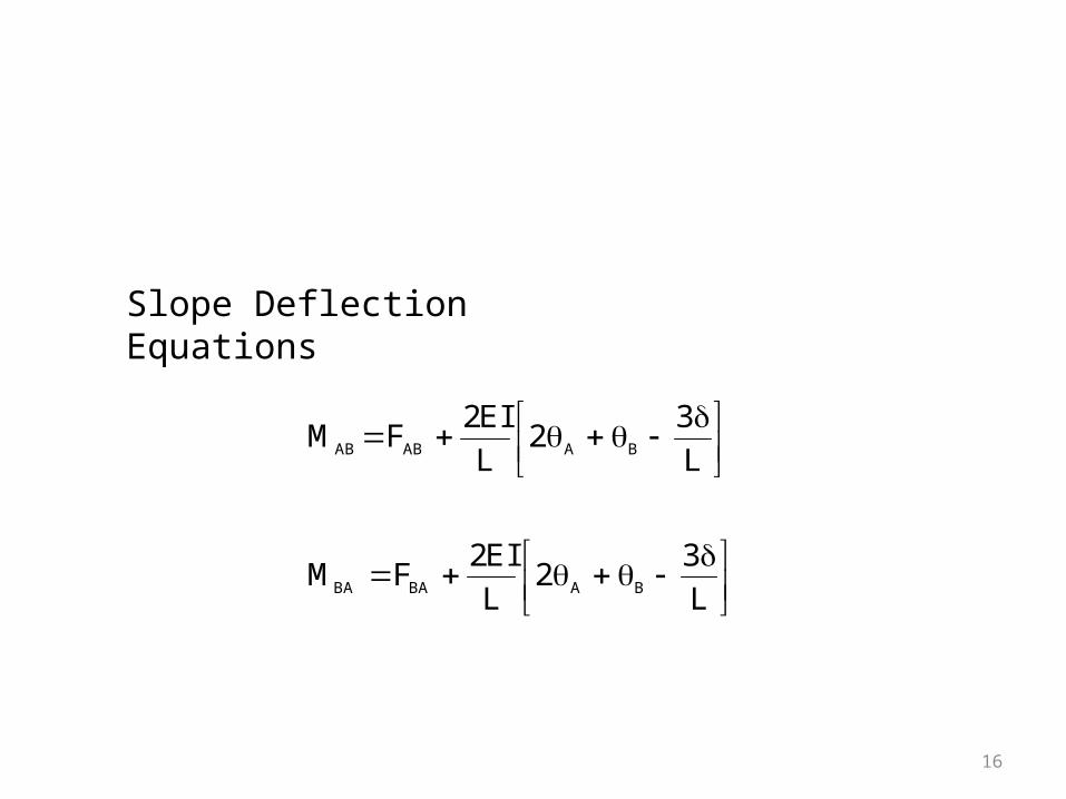
Slope Deflection Equations
L
32
L
EI2FM
L
32
L
EI2FM
BABABA
BAABAB

17
18
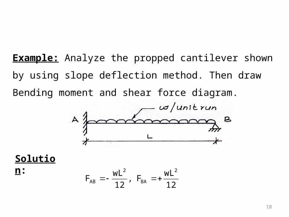
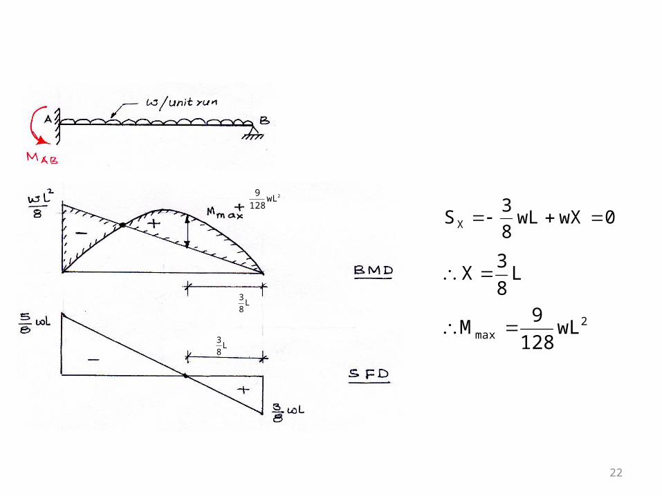
Example: Analyze the propped cantilever shown by using slope
deflection method. Then draw Bending moment and shear force
diagram.
Solution:
12
wLF,
12
wLF
2
BA
2
AB
19
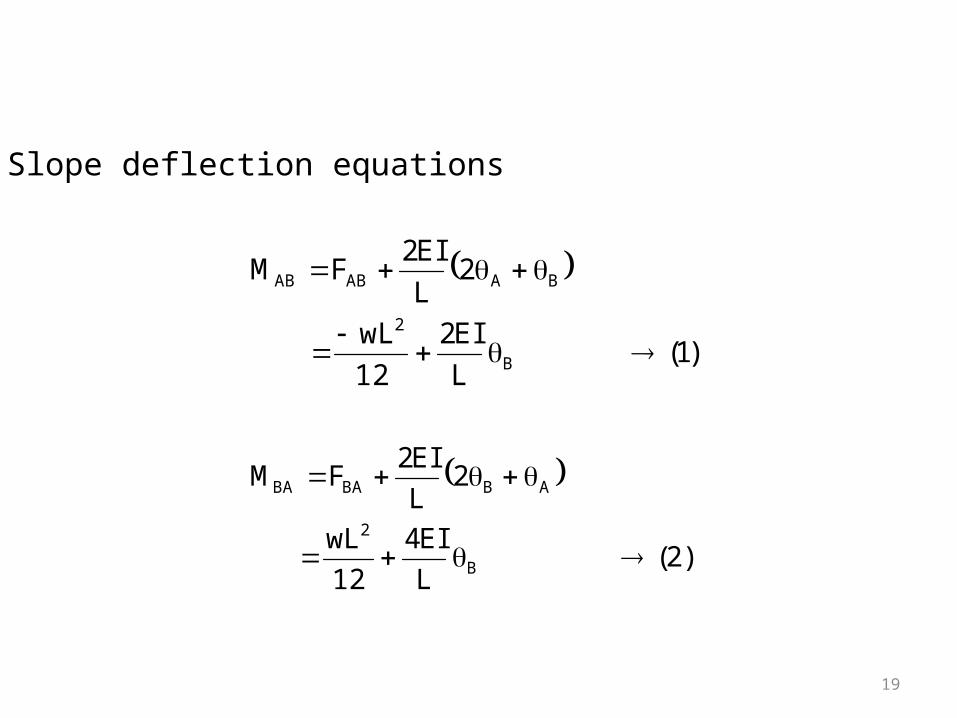
Slope deflection equations
)1(L
EI2
12
wL
2L
EI2FM
B
2
BAABAB
)2(L
EI4
12
wL
2L
EI2FM
B
2
ABBABA

20
Boundary condition at BMBA=0
0L
EI4
12
wLM B
2
BA 48
wLEI
3
B
Substituting in equations (1) and (2)
8
wL
48
wL
L
2
12
wLM
232
AB
048
wL
L
4
12
wLM
32
BA
21
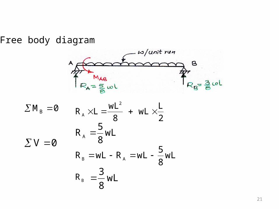
Free body diagram
wL8
5RA
0V wL
8
5wLRwLR AB
wL8
3
2
LwL
8
wLLR
2
A 0MB
BR
22
0wXwL8
3SX
L8
3X
2max wL
128
9M
L8
3
L8
3
2wL128
9
23
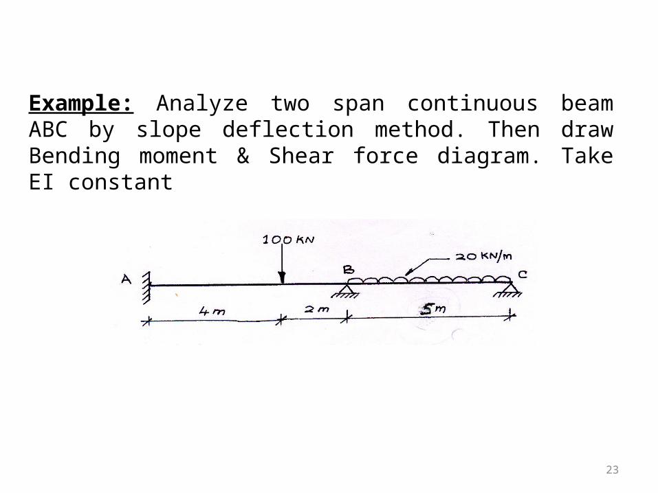
Example: Analyze two span continuous beam ABC by slope deflection method. Then draw Bending moment & Shear force diagram. Take EI constant
24
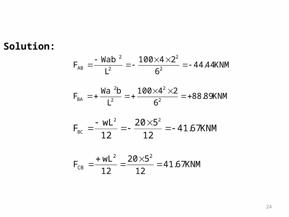
Solution:
KNM44.446
24100
L
WabF
2
2
2
2
AB
KNM89.886
24100
L
bWaF
2
2
2
2
BA
KNM67.4112
520
12
wLF
22
BC
KNM67.4112
520
12
wLF
22
CB
25
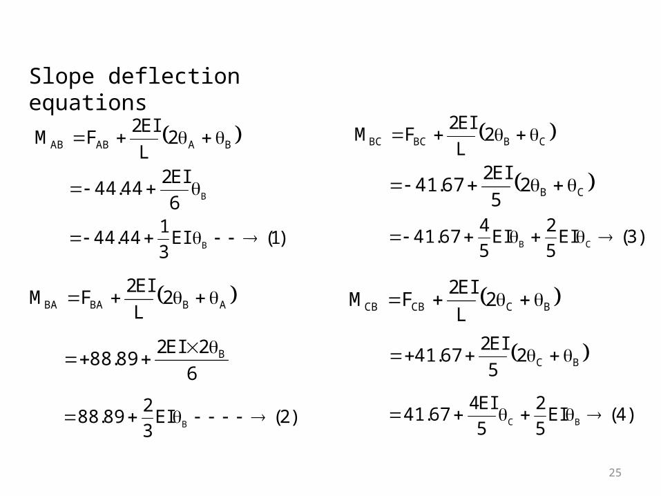
Slope deflection equations
BAABAB 2L
EI2FM
B6
EI244.44
)1(EI3
144.44 B
ABBABA 2L
EI2FM
6
2EI289.88 B
)2(EI3
289.88 B
CBBCBC 2L
EI2FM
CB25
EI267.41
)3(EI5
2EI
5
467.41 CB
BCCBCB 2L
EI2FM
BC25
EI267.41
)4(EI5
2
5
EI467.41 BC
26
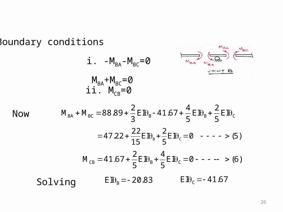
Boundary conditions
MBA+MBC=0
ii. MCB=0
CBBBCBA EI5
2EI
5
467.41EI
3
289.88MM
)5(0EI5
2EI
15
2222.47 CB
)6(0EI5
4EI
5
267.41M CBCB
83.20EI B 67.41EI C Solving
i. -MBA-MBC=0
Now
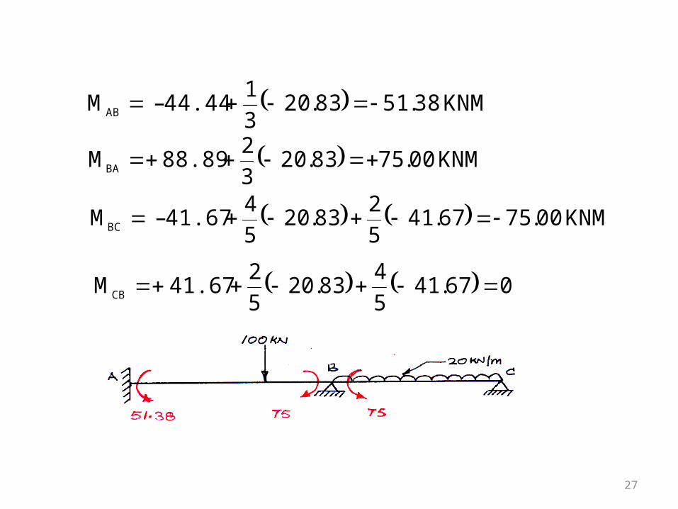
27
KNM38.5183.203
1 44.44 – MAB
KNM00.7583.203
2 88.89 MBA
KNM00.7567.415
283.20
5
441.67 – MBC
067.415
483.20
5
241.67 MCB
28
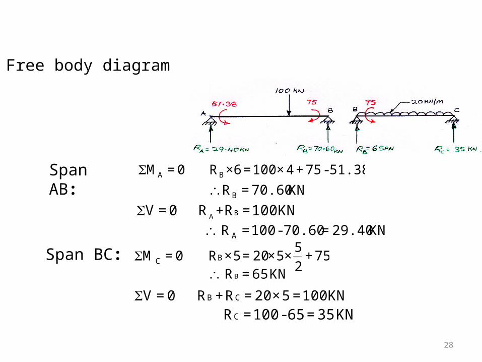
Free body diagram
Span BC:
Span AB:
75+ 2
5×5×20 = 5×R 0 = M BC
KN 65 = R B
100KN = 5×20 = R+R 0=V CBKN 35 = 65-100 = RC
51.38-75+4×100 = ×6R 0 = M BAKN 70.60 = RB
100KN = +RR0 =V BAKN 29.40=70.60-100 = R A
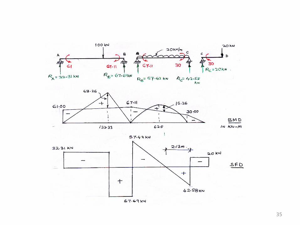
29
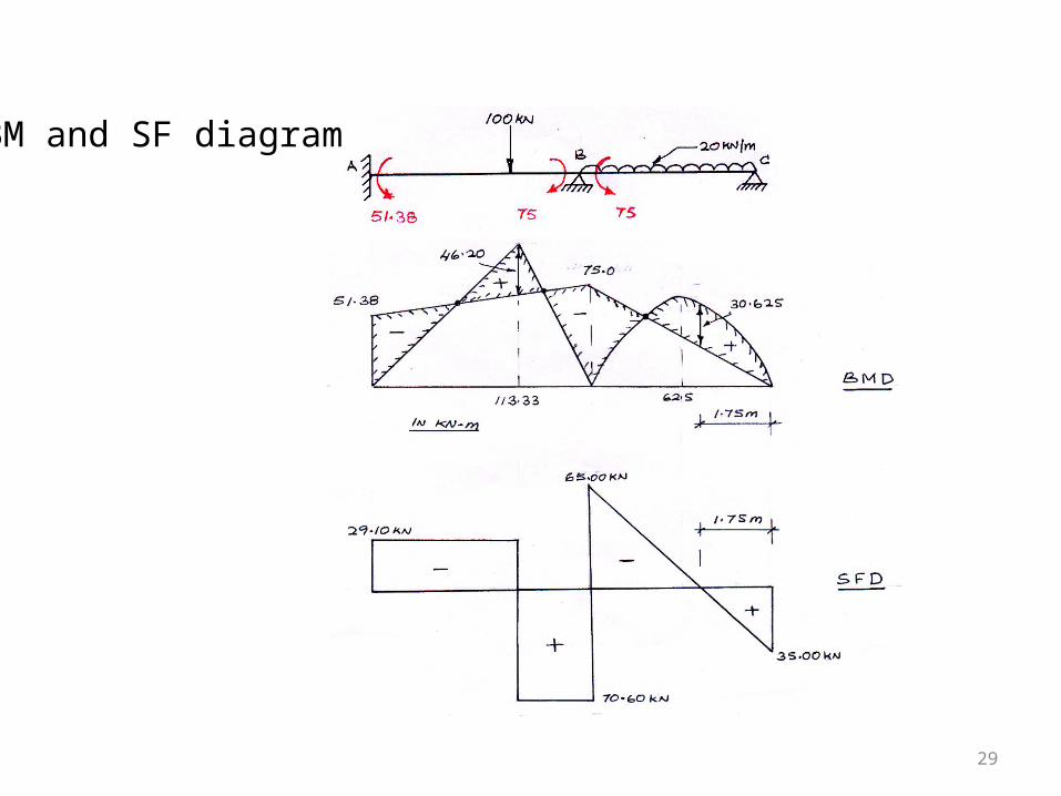
BM and SF diagram
30
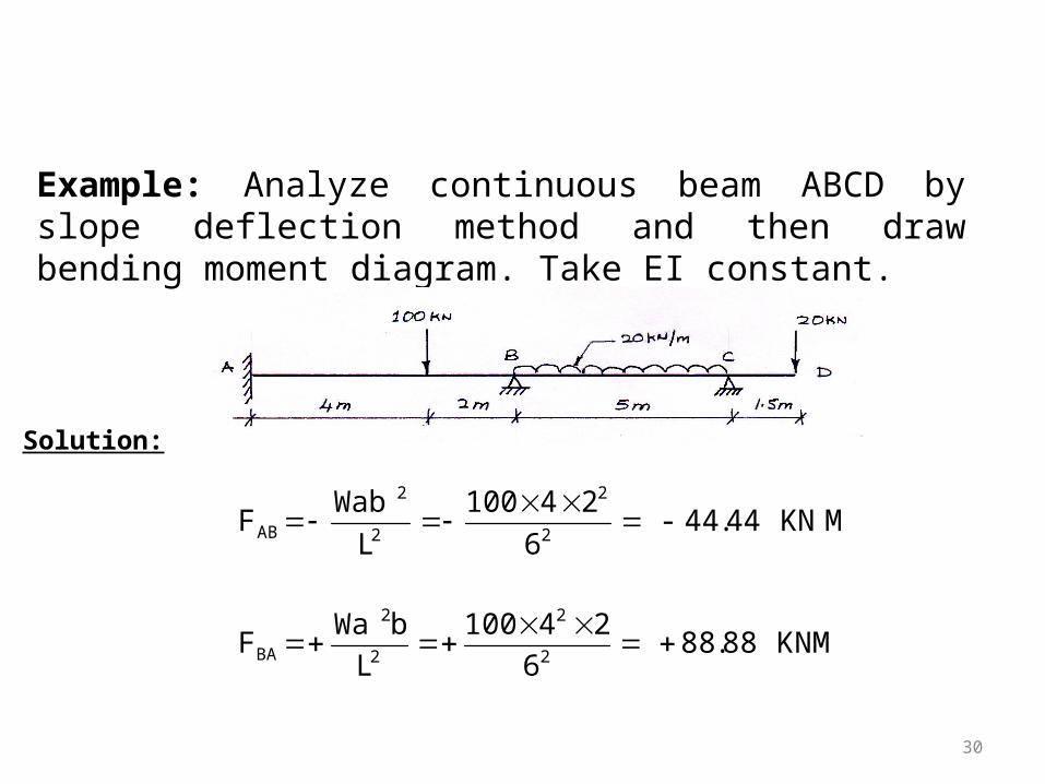
Example: Analyze continuous beam ABCD by slope deflection method and then draw bending moment diagram. Take EI constant.
Solution:
M KN 44.44 - 6
24100
L
Wab F
2
2
2
2
AB
KNM 88.88 6
24100
L
bWa F
2
2
2
2
BA
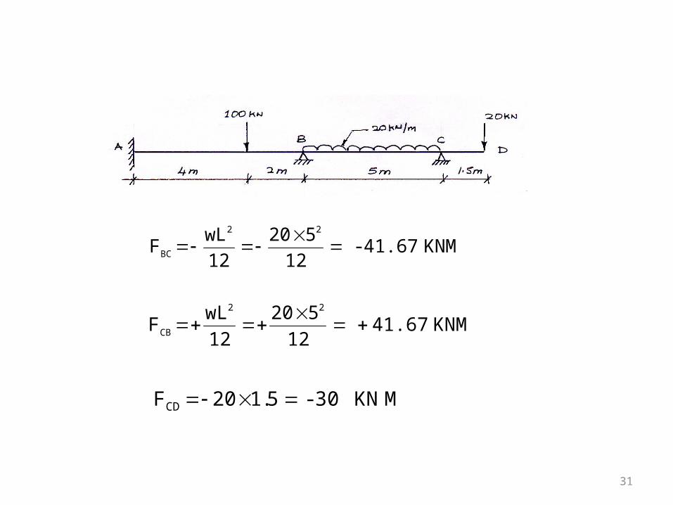
31
KNM 41.67- 12
520
12
wLF
22
BC
KNM 41.67 12
520
12
wLF
22
CB
M KN 30 - 5.120FCD
32
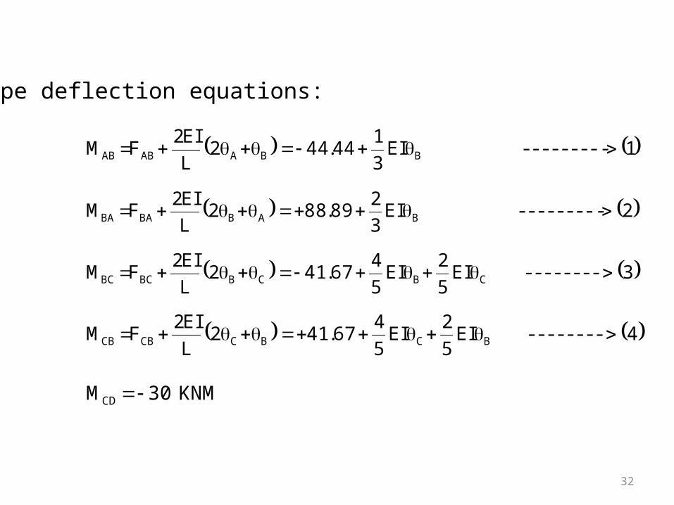
Slope deflection equations:
1--------- EI3
144.442
L
EI2FM BBAABAB
2--------- EI3
289.882
L
EI2FM BABBABA
3-------- EI5
2EI
5
467.412
L
EI2FM CBCBBCBC
4-------- EI5
2EI
5
467.412
L
EI2FM BCBCCBCB
KNM 30MCD
33
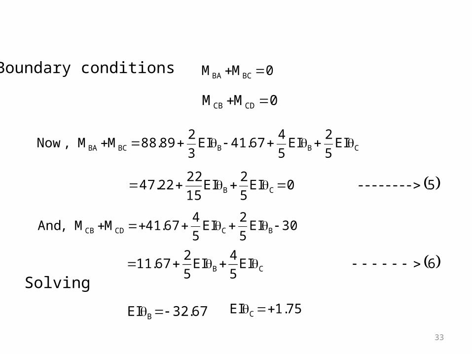
Boundary conditions 0MM BCBA
0MM CDCB
CBBBCBA EI5
2EI
5
467.41EI
3
289.88MM,Now
5-------- 0EI5
2EI
15
2222.47 CB
30EI5
2EI
5
467.41MM,And BCCDCB
6EI5
4EI
5
267.11 CB
Solving
67.32EI B 75.1EI C
34
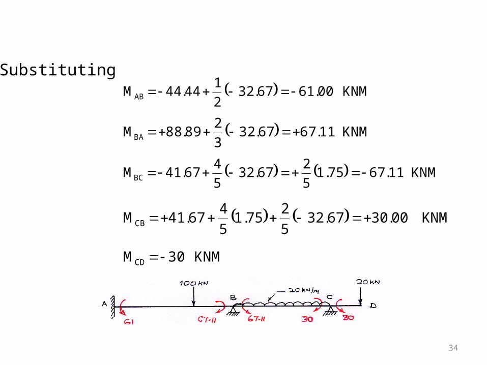
Substituting
KNM 00.6167.322
144.44MAB
KNM 11.6767.323
289.88MBA
KNM 11.6775.15
267.32
5
467.41MBC
KNM 00.3067.325
275.1
5
467.41MCB
KNM 30MCD
35
36
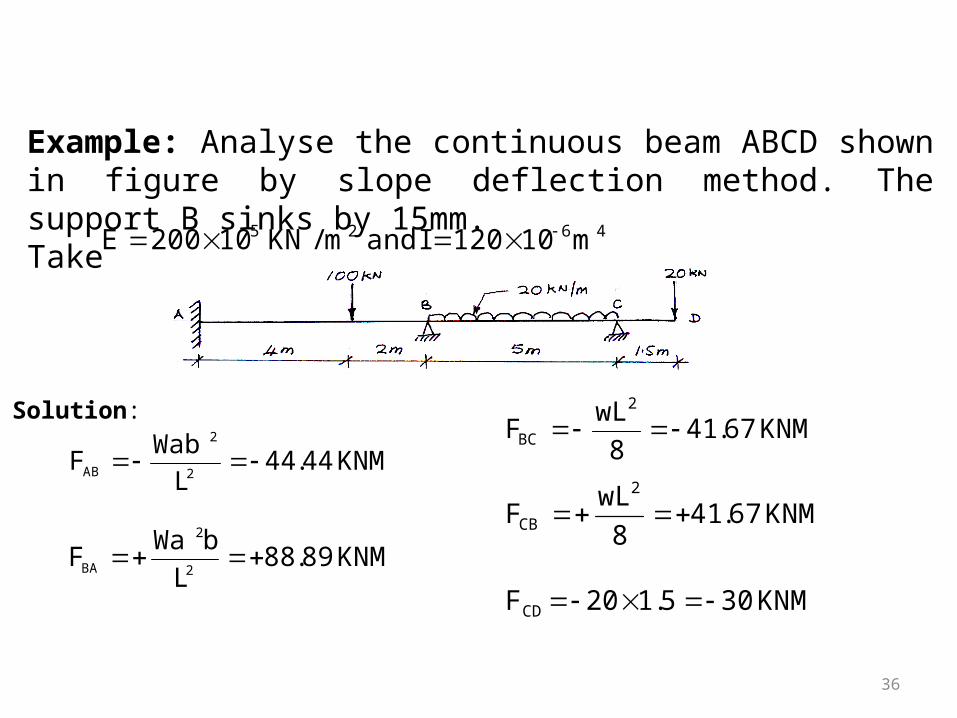
Example: Analyse the continuous beam ABCD shown in figure by slope deflection method. The support B sinks by 15mm.Take 4625 m10120Iandm/KN10200E
Solution:
KNM44.44L
WabF
2
2
AB
KNM89.88L
bWaF
2
2
BA
KNM67.418
wLF
2
BC
KNM67.418
wLF
2
CB
KNM305.120FCD
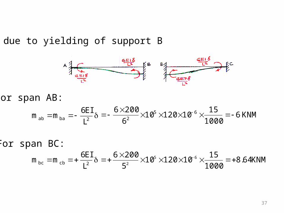
37
FEM due to yielding of support B
For span AB:
2baab L
EI6mm KNM6
1000
151012010
6
2006 652
2cbbc L
EI6mm KNM64.8
1000
151012010
5
2006 65
2
For span BC:

38
Slope deflection equation
1---------- EI3
144.50
6EI3
144.44-
L
EI62
L
EIFM
B
B2BAABAB
2------------ EI3
289.82
6EI3
288.89
L
EI6)2(
L
EI2FM
B
B2ABBABA
3--------- EI 5
2EI
5
403.33
64.82EI5
241.67-
L
EI6)2(
L
EI2FM
CB
CB2CBBCBC
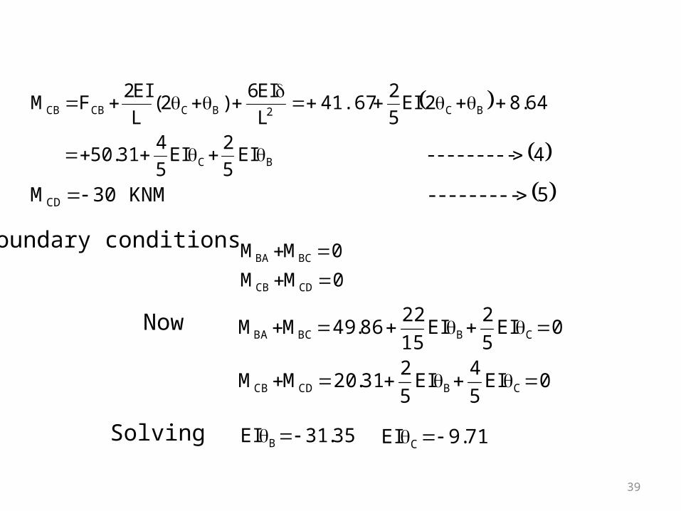
39
4--------- EI 5
2EI
5
431.50
64.82EI5
241.67
L
EI6)2(
L
EI2FM
BC
BC2BCCBCB
5--------- KNM 30MCD
Boundary conditions
0MM
0MM
CDCB
BCBA
0EI5
4EI
5
231.20MM
0EI5
2EI
15
2286.49MM
CBCDCB
CBBCBA
Now
Solving 35.31EI B 71.9EI C
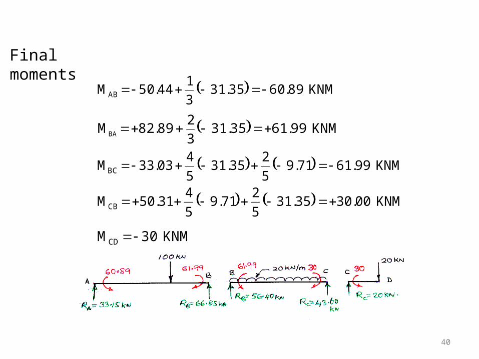
40
Final moments
KNM 89.6035.313
144.50MAB
KNM 99.6135.313
289.82MBA
KNM 99.6171.95
235.31
5
403.33MBC
KNM 00.3035.315
271.9
5
431.50MCB
KNM 30MCD
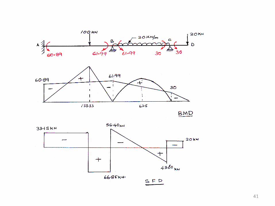
41