1 of 32© boardworks ltd 2009. 2 of 32© boardworks ltd 2009
TRANSCRIPT

1 of 32 © Boardworks Ltd 2009

2 of 32 © Boardworks Ltd 2009

3 of 32 © Boardworks Ltd 2009
Sensing devices

4 of 32 © Boardworks Ltd 2009
Light dependent resistors
A Light Dependent Resistor (LDR) is an input transducer, converting light energy to a change in electrical properties. Its resistance decreases as light intensity increases.
As photons of light hit a cadmium sulfide track, they give bound electrons enough energy to jump into the conduction band.
res
ista
nce
(Ω
)
light intensity (lux)
LDR symbol
cadmium sulfide track
The resistance can fall from 1 MΩ in darkness to 500 Ω in light.

5 of 32 © Boardworks Ltd 2009
Thermistors
Negative temperature coefficient (NTC) thermistors are input transducers that have a decreasing resistance as temperature is increased.
As the surrounding temperature increases, the electrons in the metal oxide of the thermistor gain energy. This increases the number of charge carriers, decreasing resistance.
res
ista
nce
(Ω
)
temperature (°C)
thermistor symbol

6 of 32 © Boardworks Ltd 2009
Sensors summary

7 of 32 © Boardworks Ltd 2009

8 of 32 © Boardworks Ltd 2009
Sharing voltage

9 of 32 © Boardworks Ltd 2009
Potential dividers
Potential dividers reduce voltage. Varying the ratio of a pair of resistors changes the output voltage of a circuit.
0 V
VIN
R1
R2
VOUT
VOUT will be a fraction of VIN. The magnitude of VOUT is dependent upon the ratio of the two resistors R1 and R2.
VOUT
0 V
=R2
VINR1 + R2
×

10 of 32 © Boardworks Ltd 2009
Using the potential divider equation

11 of 32 © Boardworks Ltd 2009
Sensors and potential dividers

12 of 32 © Boardworks Ltd 2009
Potential divider questions

13 of 32 © Boardworks Ltd 2009
Potential dividers summary

14 of 32 © Boardworks Ltd 2009

15 of 32 © Boardworks Ltd 2009
Electrical power
power (W) = voltage (V) × current (A)
The power, or rate of energy transfer, of a device is a product of the voltage and current passing through the component.
What is the power of a bulb which uses a 230 V mains supply and has a current of 0.44 A passing through it?
What is the voltage across a microchip if it has a normal operating power of 0.5 W and draws a current of 0.1 A?
V = P ÷ I
P = V × I = 230 × 0.44 = 101.2 W
= 0.5 ÷ 0.1 = 5 V

16 of 32 © Boardworks Ltd 2009
Different forms of the power equation
Electrical power can also be calculated using resistance.
P = V × I
P = I2 × R P = V2 ÷ R
and… V = I × R
P = V × I
Therefore, using substitution:
P = I × R × I
and… I = V ÷ R
P = V × V ÷ R
Therefore, using substitution:
The equations linking power to resistance are found by substituting the equation V = I × R into the power equation:

17 of 32 © Boardworks Ltd 2009
Energy in circuits

18 of 32 © Boardworks Ltd 2009
A light bulb converts electrical energy to useful light and wasted heat.
Efficiency
Efficiency is a measure of how well a device transforms energy into useful forms.
light
What is the efficiency of the bulb if it converts 50 J of electrical energy into 45 J of heat energy?
efficiency =
=
electricalheat
× 100useful energy out
total energy in
× 100 = 10 %5
50

19 of 32 © Boardworks Ltd 2009
Efficiency of a motor
What is the efficiency of this system, if the motor takes 5 seconds to lift the weight?
(take gravity to be 9.81 N/kg)
1.4 kg
1.5
m
6 V 2 A
motor
pulley
=efficiency =useful energy out
total energy in× 100
energy into system: electrical energy = I × t × V = 2 × 5 × 6 = 60.0 J
energy used:gravitational potential energy = m × g × h
= 1.4 × 9.81 × 1.5 = 20.6 J
60.0= 34.3 %
20.6× 100

20 of 32 © Boardworks Ltd 2009
Electricity in the home

21 of 32 © Boardworks Ltd 2009
22 of 32 © Boardworks Ltd 2009
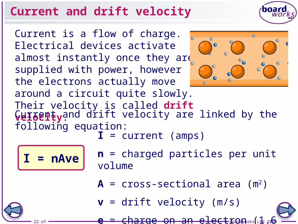
Current and drift velocity
Current is a flow of charge. Electrical devices activate almost instantly once they are supplied with power, however the electrons actually move around a circuit quite slowly. Their velocity is called drift velocity.
Current and drift velocity are linked by the following equation:
I = nAve
I = current (amps)
n = charged particles per unit volume
A = cross-sectional area (m2)
v = drift velocity (m/s)
e = charge on an electron (1.6 x 10⁻¹⁹ C)

23 of 32 © Boardworks Ltd 2009
Understanding I = nAve

24 of 32 © Boardworks Ltd 2009
Alternating current and direct current

25 of 32 © Boardworks Ltd 2009
RMS voltage
The voltage of AC can be viewed using an oscilloscope. There are three common voltage measures, namely peak, peak-to-peak and RMS (root mean squared) voltage.
RMS is a measure of the average magnitude of the voltage. VRMS =
VPEAK
√2
RMS voltage
zero volts
peak voltage
peak-to-peak voltage

26 of 32 © Boardworks Ltd 2009
RMS current and RMS power
To investigate voltage we use an oscilloscope connected across a resistor. As V I, the equation for calculating RMS current is similar to the equation for RMS voltage:
IRMS
The equation for RMS power is a little different:
PPEAK = IPEAK × VPEAK
PRMS = IRMS × VRMS =
PRMS =
=IPEAK
√2
×IPEAK
√2
VPEAK
√2PPEAK
2

27 of 32 © Boardworks Ltd 2009
AC calculations

28 of 32 © Boardworks Ltd 2009
AC/DC summary

29 of 32 © Boardworks Ltd 2009

30 of 32 © Boardworks Ltd 2009
Glossary

31 of 32 © Boardworks Ltd 2009
What’s the keyword?

32 of 32 © Boardworks Ltd 2009
Multiple-choice quiz