1. overview · scott-t & wye transformers: excessive voltage transients can occur when...
TRANSCRIPT

1© Control Concepts Inc., 2014www.ccipower.com 1-800-765-2799MicroFUSION Operator’s Manual Rev 2.33
1. OVERVIEW MicroFUSION is an ultra-compact high-performance microprocessor-based power controller, available in single, three phase, or three phase two leg models to control AC loads.
Resistive or transformer-connected loads can be controlled in either Phase Angle, Zero Cross, or Zero Cross Transformer (ZCT) Mode. Output is controlled linearly with respect to command signal and can be set to the average or RMS value of the voltage and current, as well as true instantaneous power or external feedback.
MicroFUSION Series power controllers are available in current ratings from 16, 32, 50, 80 amps AC. Auto-ranging voltage circuitry enables main supply voltage from 24-600 VAC, (45-65 Hz) eliminating the need for hardware jumpers or stocking multiple controllers for international voltages. A separate 24 Vdc power source supplies the control electronics and maintains critical communications to your control system when the mains are absent.
Status LEDs and an LED bar graph make operation and troubleshooting simple. A plug-n-play USB interface and free MicroFUSION Control Panel software for the PC further simplifies installing and configuring the controller to your application. For example, controller settings can be duplicated simply by loading a configuration file saved from a previous unit.
Setpoints can be controlled through the standard analog or optional digital fieldbus interface. The factory-configured analog setpoint signal ranges are 0 - 5 Vdc and 4 - 20 mA, both of which are field scalable from 0 - 10 Vdc or 0 - 20 mA.
External fieldbus interface options include DeviceNet™, EtherNet/IP, EtherCAT, PROFINET, Modbus RTU (RS-485), or Modbus TCP. These can be used to communicate with a PLC or factory control system. PROFINET, Modbus TCP, and EtherNet/IP are available as internal fieldbus options. Furthermore, a single external network module can control up to ten zones, reducing system installation costs.
The robust design of MicroFUSION allows for continuous full-frame current operation - without derating - at up to 50° C / 6000 ft altitude. Cooling is accomplished through either natural convection, forced air, optional external panel mount, or optional liquid-cooled chill plate.
1.1 Certifications / Markings
In addition to certification markings, the controllers will also be marked with: Model Number Serial Number Voltage Range (24 - 600 Vac) Current Size Control Concepts contact information Frequency (45 - 65 Hz) Torque information on Line / Load connections
Part 15 Subpart BClass A DeviceEN60947-4

© Control Concepts Inc., 2014 www.ccipower.com 1-800-765-27992 MicroFUSION Operator’s Manual Rev 2.33
H
F
1.2 Points of InterestA. CCI LINK™A proprietary deterministic digital bus that enables multiple Control Concepts devices to communicate with each other.
B. DIGITAL COMMUNICATIONS OPTIONPROFINET, Modbus TCP, and EtherNet/IP are available as internal fieldbus options.
C. RETRANSMITS & RELAY CONNECTIONS(P2) Retransmits and Relay
D. OPTIONAL REMOTE DISPLAYShows parameter name with information such as setpoints, limit settings, monitor features, alarms, and more. The display can be easily mounted outside an electrical panel for efficiency.
BCD
A
E
E. COMMAND CONNECTIONS(P1) Analog inputs, general purpose input, + 24 Vdc supply, run/stop
F. INDICATOR LEDsAssist with Diagnostics
G. CONTROLLER RESETMicroFUSION processor can be reset externally
H. USB PORTStreamlines controller setup with the use of the MicroFUSION control panel.
G
3© Control Concepts Inc., 2014www.ccipower.com 1-800-765-2799MicroFUSION Operator’s Manual Rev 2.33
1.3 Feature ComparisonMicroFUSION is available with one of two circuit boards. SX is a lower-cost alternative, whereas HX is a fully populated board that can be field-upgraded to include retransmits and other features.
= Included ¢ = Field Upgradable Option = Option Available at Manufacturing Time - = Not available
FEATURE LIST SX HX24-600 VAC Auto-Ranging Input
Phase Angle and Zero Cross Firing Modes
LED Bar Graph
Touchsafe Design
UL-Listed, CE, 100kA SCCR, and RoHS certifications
Micro USB Connection (USB Plug-N-Play)
Free Control Panel Software
DIN Rail Mountable
Panel Mount
RUN/STOP
Overcurrent Trip
Analog Input (0-10V, 0/4-20 mA or potentiometer)
CCI Link™ Connectivity
Fixed Current Limit - 105% of Frame -Adjustable Current Limit ¢
Alarm Relay ¢
Current Control ¢
Load Voltage Control -
Voltage Limit -
Monitor Current ¢ ¢
Analog Channel 2 Input ¢ ¢
General Purpose Input ¢ ¢
Pulse Width Modulation Input ¢ ¢
Accessory Option: Remote Display ¢ ¢
SYNC-GUARD™ Connectivity ¢ ¢
External Fieldbus Options: DeviceNet, Modbus TCP, Modubs RTU, EtherNet/IP, PROFINET, EtherCat ¢ ¢
Internal Fieldbus Options: PROFINET, Modbus TCP, and EtherNet/IP
External Panel Mount Heatsink
Water-Cooled Heatsink
Zero Cross Transformer Firing Mode - ¢
Retransmit (RTX): 2x High Resolution Analog Retransmits 0-10 VDC or 0/4-20 mA - ¢
Power Limit - ¢
True Power Control - ¢
Monitor True RMS Power - ¢
High Resolution Control Loop - ¢
© Control Concepts Inc., 2014 www.ccipower.com 1-800-765-27994 MicroFUSION Operator’s Manual Rev 2.33
1.4 Model Options & DescriptionSingle Phase ACThe single phase AC power controller is a phase angle or zero cross fired controller. It linearly controls, with respect to the setpoint, the AC voltage, current or true power applied to an electrical load. Control is achieved by means of a pair of inverse parallel SCR’s.
Three Phase - Two LegThe three phase two leg AC power controller is a zero cross fired controller. It linearly controls, with respect to the setpoint, the AC voltage, current, or true power applied to an electrical load. Control is achieved by two pairs of inverse parallel SCR’s.
Three Phase - Three LegThe three phase three leg AC power controller is a phase angle or zero cross fired controller. It linearly controls, with respect to the setpoint, the AC voltage, current or true power applied to an electrical load. Control is achieved by three pairs of inverse parallel SCR’s.
1.5 Load TypesLoads / Applications
TransformersScott-T & Wye transformers: Excessive voltage transients can occur when operating Scott-T transformers with an open or unloaded secondary. It is recommended that Scott-T transformer be limited to a maximum of 480 Volts.
1. Constant Resistive Loads (Nickel Chromium)2. Variable Resistive Loads a. Silicon Carbide b. Molybdenum Disilicide c. Graphite d. Tungsten Lamps
3. Transformer Coupled Loads4. Inductive (not intended for motor applications)5. Gas Discharge a. Ultra Violet6. Electron Beam 7. Crystal Growing and Processing
NOTE: It is recommended that a Delta to 4-Wye transformer be used to power a 4-wire Wye load. Delta to 3-wire Wye transformers are acceptable, but Wye to Wye transformers are not suited for use between the controller and load due to possible transient conditions.
5© Control Concepts Inc., 2014www.ccipower.com 1-800-765-2799MicroFUSION Operator’s Manual Rev 2.33
2. INSTALLATION2.1 Mounting Considerations
Mount controllers vertically.
The keep out area on the top and bottom is for air circulation. The top and bottom of the controller must have a minimum of 3.00 [76.2] free from obstructions as measured from the edge of the heatsink fins. Dimensions above are measured from the edge of the heatsink base.
Mounting hardware (Not included):Figures above show dimensions for din rail mounting. For mounting hardware when not using din rail, use the following: Single Phase #10 or M5 screws with star washers Three Phase #8 or M4 screws with star washers
Din rail and/or screws are not provided.
Keep Out Area
Air Flow
Dimensions:Inches
2.50
2.50
2.30
0.69
2.55
2.55
1.50
0.69

© Control Concepts Inc., 2014 www.ccipower.com 1-800-765-27996 MicroFUSION Operator’s Manual Rev 2.33
2.1.1 Single Phase (16 - 32 Amps)
Dimensions:Inches [mm]
Height6.00 [152.4]
Width2.00 [50.8]
Depth5.10 [129.54]
0.20
0.30
2.001.70
5.806.00
0.801.52
Pluggable terminal block Ring Terminal
7© Control Concepts Inc., 2014www.ccipower.com 1-800-765-2799MicroFUSION Operator’s Manual Rev 2.33
2.1.2 Single Phase (50 - 80 Amps)
Dimensions:Inches [mm]
Height6.00 [152.4]
Width3.25 [82.55]
Depth5.10 [129.54]
0.20
0.302.953.25
5.806.00
0.801.52
Pluggable terminal block Ring Terminal

© Control Concepts Inc., 2014 www.ccipower.com 1-800-765-27998 MicroFUSION Operator’s Manual Rev 2.33
2.1.3 Three Phase (16 - 80 Amps)
Dimensions:Inches [mm]
Height7.78 [197.61]
Width5.50 [139.7]
Depth6.40[162.56]
0.50
7.55
1.00
4.505.50
0.23
7.78
2.75
Three Phase Two Leg (16 - 80 Amps)

9© Control Concepts Inc., 2014www.ccipower.com 1-800-765-2799MicroFUSION Operator’s Manual Rev 2.33
Three Phase Two Leg (16 - 80 Amps)2.1.4 Three Phase External Mount Heatsink (16 - 50 Amps)
1.10 [27.9]
3.00 [76.2]
3.00 [76.2]
1.20 [30.5]
1.88 [47.6]
1.70 [43.2]
1.45 [36.8]
3.50 [88.9] 1.45 [36.8]
2.20 [55.9]
7.55 [191.8]
5.60 [142.2] 2.05 [52.1]
(10) 10-32 UNF-2B [M4x0.7 - 6H]
PANEL CUTOUT
9.75 [247.7]
12.00 [304.8]
2.41 [61.1]
3.02 [76.7]
5.47 [138.9]
1.10 [27.9]
3.00 [76.2]
3.00 [76.2]
1.20 [30.5]
1.88 [47.6]
1.70 [43.2]
1.45 [36.8]
3.50 [88.9] 1.45 [36.8]
2.20 [55.9]
7.55 [191.8]
5.60 [142.2] 2.05 [52.1]
(10) 10-32 UNF-2B [M4x0.7 - 6H]
PANEL CUTOUT
9.75 [247.7]
12.00 [304.8]
2.41 [61.1]
3.02 [76.7]
5.47 [138.9]
1.10 [27.9]
3.00 [76.2]
3.00 [76.2]
1.20 [30.5]
1.88 [47.6]
1.70 [43.2]
1.45 [36.8]
3.50 [88.9] 1.45 [36.8]
2.20 [55.9]
7.55 [191.8]
5.60 [142.2] 2.05 [52.1]
(10) 10-32 UNF-2B [M4x0.7 - 6H]
PANEL CUTOUT
9.75 [247.7]
12.00 [304.8]
2.41 [61.1]
3.02 [76.7]
5.47 [138.9]
Dimensions:Inches [mm]
Height12.00 [304.8]
Width9.75 [247.7]
Depth5.47 [138.9]
© Control Concepts Inc., 2014 www.ccipower.com 1-800-765-279910 MicroFUSION Operator’s Manual Rev 2.33
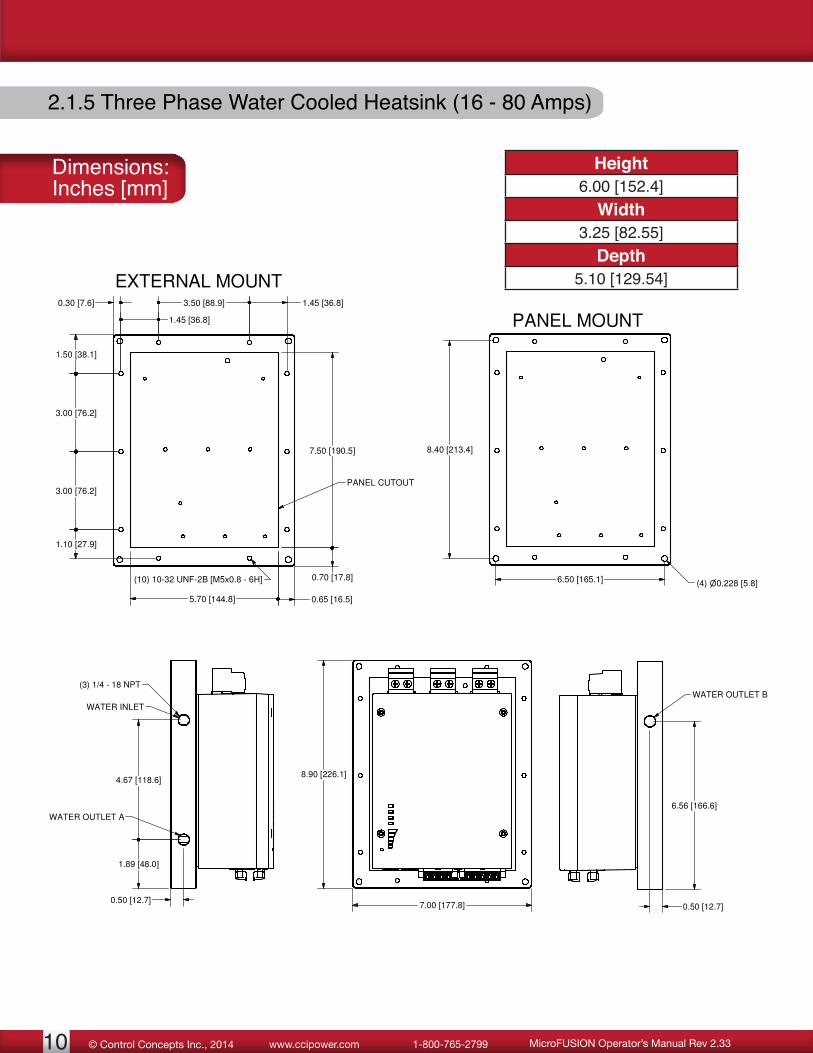
2.1.5 Three Phase Water Cooled Heatsink (16 - 80 Amps)
0.30 [7.6]
1.45 [36.8]
3.50 [88.9] 1.45 [36.8]
1.10 [27.9]
3.00 [76.2]
3.00 [76.2]
1.50 [38.1]
0.70 [17.8]
7.50 [190.5]
5.70 [144.8] 0.65 [16.5]
(10) 10-32 UNF-2B [M5x0.8 - 6H]
PANEL CUTOUT
8.40 [213.4]
6.50 [165.1] (4) 0.228 [5.8]
PANEL MOUNT
EXTERNAL MOUNT
8.90 [226.1]
7.00 [177.8]0.50 [12.7]
1.89 [48.0]
4.67 [118.6]
WATER INLET
WATER OUTLET A
(3) 1/4 - 18 NPT
0.50 [12.7]
6.56 [166.6]
WATER OUTLET B
Dimensions:Inches [mm]
Height6.00 [152.4]
Width3.25 [82.55]
Depth5.10 [129.54]
11© Control Concepts Inc., 2014www.ccipower.com 1-800-765-2799MicroFUSION Operator’s Manual Rev 2.33
3. WIRINGControl Concepts configures and tests each controller before shipping. Once received, the controller is ready to install. The following sections will describe how to properly wire the unit with the recommended fusing.
For line and load connections use copper conductors rated 75°C minimum. See torque tables for proper tightening.
A ground wire is recommended for proper operation. Use 10 AWG or larger wire.
Note: Wire controllers to conform with the National Electric Code (NEC) and/or other local wiring codes.
3.1 Torque Specifications
Recommended Tightening Torque For P1/P2 Connectors
Number of wires
Wire Size (AWG)
Torque
1 16 - 26 3.0 IN-LBS [0.34 Nm]2 20 3.0 IN-LBS [0.34 Nm]
Recommended Tightening Torque For Line/Load Connectors
Wire Size (AWG) Torque3 - 14 24 IN-LBS [2.70 Nm]

© Control Concepts Inc., 2014 www.ccipower.com 1-800-765-279912 MicroFUSION Operator’s Manual Rev 2.33
3.2 AC Line / Load Connections
3.2.1 Single Phase
A2B1
A1
A1B1PE GND
LOAD
FUSES
1 2
3 4
5 6
7 8
1 2
3 4
5 6
7 8
9 1
0
A2B1 A1
B1 uses #6 or M3.5 ring terminal.A1 and A2 use #10 or M5 ring terminal. See drawing above for wiring

13© Control Concepts Inc., 2014www.ccipower.com 1-800-765-2799MicroFUSION Operator’s Manual Rev 2.33
3.2.2 Three Phase, 2 Leg
L O A D
LOAD
LOAD
LO
AD
LO
AD
LO AD
A1A2B1B2C REF
FUSES
A1
B1
C1
PE GND

© Control Concepts Inc., 2014 www.ccipower.com 1-800-765-279914 MicroFUSION Operator’s Manual Rev 2.33
3.2.3 Three Phase, Delta or Wye
L O A D
LOAD
LOAD
LO
AD
LO
AD
LO AD
A1A2B1B2C1C2
FUSES
A1
B1
C1
PE GND
15© Control Concepts Inc., 2014www.ccipower.com 1-800-765-2799MicroFUSION Operator’s Manual Rev 2.33
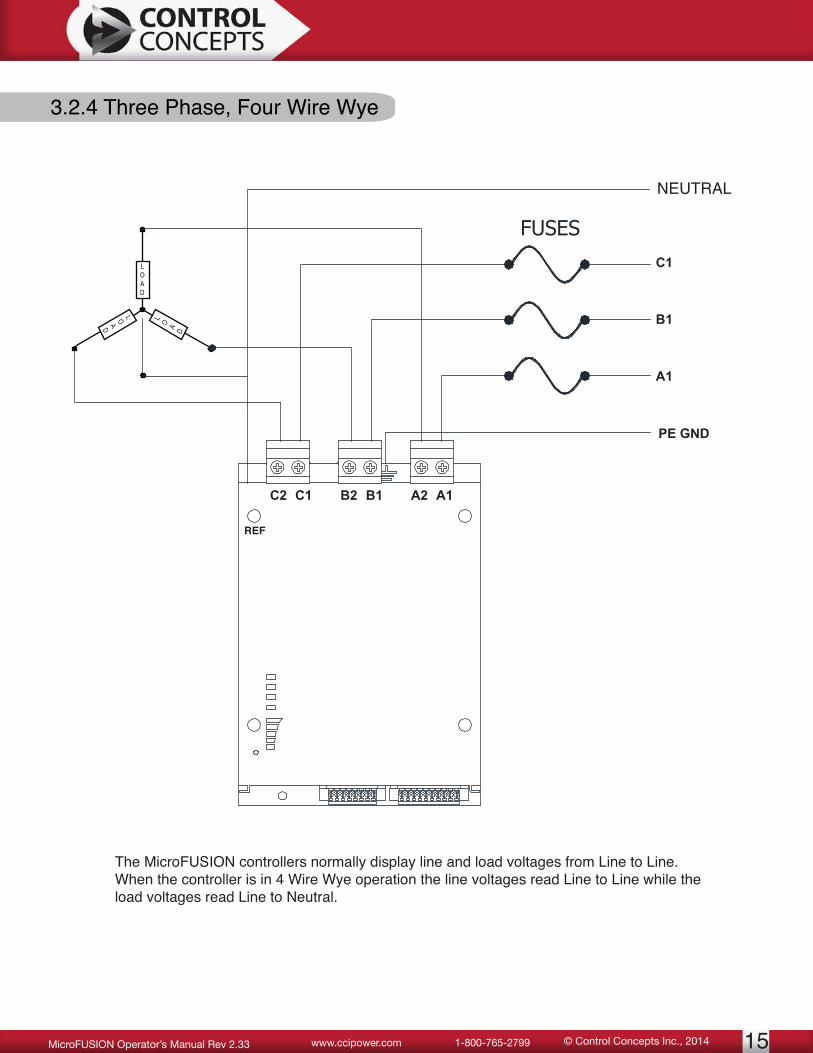
3.2.4 Three Phase, Four Wire Wye
The MicroFUSION controllers normally display line and load voltages from Line to Line. When the controller is in 4 Wire Wye operation the line voltages read Line to Line while the load voltages read Line to Neutral.
L O A D
LOAD
LOAD
A1A2B1B2C1C2
FUSES
A1
B1
C1
PE GND
NEUTRAL
REF
© Control Concepts Inc., 2014 www.ccipower.com 1-800-765-279916 MicroFUSION Operator’s Manual Rev 2.33
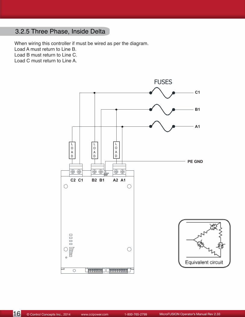
3.2.5 Three Phase, Inside Delta
LOAD
A1A2B1B2C1C2
FUSES
A1
B1
C1
PE GND
LOAD
LOAD
When wiring this controller if must be wired as per the diagram.Load A must return to Line B.Load B must return to Line C.Load C must return to Line A.

17© Control Concepts Inc., 2014www.ccipower.com 1-800-765-2799MicroFUSION Operator’s Manual Rev 2.33
+ - + - No Connect NO Relay (250 VAC Form C) C NC
3.3 Connectors
3.3.1 P1-10 Pin Command Connector
3.3.2 P2-8 Pin Command Connector
24 Vdc Input
Analog Input SP 1
Analog Input SP 2
- +5 Vdc (onboard supply up to 10 mA) + - + - Common Run/StopGeneral Purpose Input (Optional)
Retransmit 1
Retransmit 2

© Control Concepts Inc., 2014 www.ccipower.com 1-800-765-279918 MicroFUSION Operator’s Manual Rev 2.33
4. INDICATOR LEDsSee chart below for LED Colors and indicated Operation.
24VDCGreen +24 Vdc presentRed +24 Vdc wired backwards
LINE OKOff No AC Line VGreen Ok, LockedOrange Boot SegmentRed Phase Lock Loss
LIMITOff Ok, No LimitsOrange Voltage LimitRed Current LimitFlash between Red/Green
Power Limit
ALARMOff Ok, No Alarms, Not in
RUNGreen Ok, No Alarms, in RUNOrange Warning AlarmRed Inhibit Alarm
OUTPUTGreen LEDs turn green in pro-
portion to outputTop LED Red Indicates 100% on

19© Control Concepts Inc., 2014www.ccipower.com 1-800-765-2799MicroFUSION Operator’s Manual Rev 2.33
5. USB INTERFACE5.1 USB InterfaceA MicroUSB interface is standard on all controllers. Included with each controller is a software package titled ‘MicroFUSION Control Panel’. This allows the user to connect to the controller using a computer and MicroUSB cable.
Control Concepts stocks 15 foot USB cables for customers to purchase (P/N: 0058006-0000-15).
6. OPTION BOARD6.1 Internal Factory Industrial Communications
A fieldbus interface options can be used to communicate with a PLC or factory control system. PROFINET, Modbus TCP, and EtherNet/IP are available as internal fieldbus options.
Control Concepts highly recommends the use of shielded wiring and offers a variety of lengths to purchase.
6.2 External Factory Industrial CommunicationsDeviceNet™, EtherNet/IP, EtherCAT, PROFINET, Modbus RTU (RS-485), or Modbus TCP are available through an external module. Furthermore, a single external network module can control up to 10 zones, reducing system installation costs.
Control Concepts highly recommends the use of shielded wiring and offers a variety of lengths to purchase.
See Fieldbus module in the Accessories section of this manual for more details.
Note: Only one type of interface is available per unit. For example a controller with Modbus RTU cannot also have Modbus TCP.

© Control Concepts Inc., 2014 www.ccipower.com 1-800-765-279920 MicroFUSION Operator’s Manual Rev 2.33
7. PERFORMANCE7.1 Feedback [SP 1]
SX HXFF Voltage * Included * IncludedRMS Voltage N/A optionalAVG Voltage N/A optionalRMS Current N/A optionalAVG Current N/A optionalReal Power N/A optionalApparent Power N/A optional
The Feedback type determines how the control loop feedback works.
FF Voltage – Use RMS Voltage based on line voltage as the control loop feedback.RMS Voltage – Use RMS Voltage as the control loop feedback.AVG Voltage – Use average voltage as the control loop feedback.RMS Current – Use RMS current as the control loop feedback.AVG Current – Use average current as the control loop feedback.Power – Use real power as the control loop feedbackApparent Power – Use apparent power as the control loop feedback.
7.1.1 Feedback Type CalculationsHere are the calculations on how the feedback is measured:
Vpk = Peak Voltage Ipk = Peak CurrentVi = Instantaneous Voltage sample Ii = Instantaneous Current samplen = number of samples in 1 AC line cycle
* = defaultThe optional feedback types are only available if the Per-formance section of the model number contains a “P”.
PowerThe output is adjusted via the real Power.
Real Power = i = 1
n
n
Apparent Power = Vrms * Irms
Power Factor = Apparent Power
Real Power
RMS Voltage
Vrms = i = 1
n
n
2
= 0.707 Vpk
AVG Voltage
Vavg = 1.11 n
i = 1
n
= 0.707 Vpk
RMS Current
Irms = i = 1
n
n
2
= 0.707 Ipk
AVG Current
Iavg = 1.11 n
i = 1
n
= 0.707 Ipk
(Vi) (Ii)
| Ii ||Vi |
(Vi* Ii)

21© Control Concepts Inc., 2014www.ccipower.com 1-800-765-2799MicroFUSION Operator’s Manual Rev 2.33
7.1.2 External Feedback
External feedback uses an external analog signal to represent the output to the load. These types of signals often come from a transducer that measures voltage, current, temperature or power and scales it proportionally to a 0 – 5 Vdc or 4 – 20 mA signal. Connect the external feedback signal to an analog setpoint. Select the correct Feedback Source (SP19). Scale the external feedback by setting up the analog setpoint via the Analog I/O tab of the Control Panel software. 7.1.3 Feedback Source [SP19]
SX HXInternal * Included * IncludedAnalog SP1 Included IncludedAnalog SP2 Optional Optional
This selects the type of feedback used. For external feedback select Analog SP1 or SP2.
* = defaultThe Analog SP2 source is only available if the I/O section of the model number contains a “2” or “3”.

© Control Concepts Inc., 2014 www.ccipower.com 1-800-765-279922 MicroFUSION Operator’s Manual Rev 2.33
100% Load Power 50% Load Power 25% Load Power
100% Load Power 50% Load Power 25% Load Power
Single Phase Operation
Three Phase Operation
Note: For proper load operation, correct wiring is critical. See the “Wiring” section of the Installation & Maintenance Manual.
7.2 Firing Mode [SP 2]SX HX
Zero Cross Included * IncludedPhase Angle ** Included ** IncludedZero Cross Transformer N/A optional
Knowing the application and the type of load you are trying to control is critical for choosing the right mode of operation. The MicroFUSION Series power controllers are capable of Phase Angle, Zero Cross, and ZCT operations. The following sections will describe each type of operation and will show the expected output.
7.2.1 Phase Angle
In phase-angle control, each SCR of the back-to-back pair is turned on for a variable portion of the half-cycle that it conducts. Power is regulated by advancing or delaying the point at which the SCR is turned ON within each half cycle. Light dimmers are an example of phase-angle control.
Phase-angle control provides a very fine resolution of power and is used to control fast responding loads such as tungsten-filament lamps or loads in which the resistance changes as a function of temperature.
* = default for three phase 2 leg** = default for all other modelsThe Zero Cross Transformer mode is only available if the Zero Cross Transformer Mode section of the model number contains a “Z”.

23© Control Concepts Inc., 2014www.ccipower.com 1-800-765-2799MicroFUSION Operator’s Manual Rev 2.33
7.2.2 Zero Cross
In zero-cross control, load power is turned ON and OFF only when instantaneous value of the sinusoidal waveform is zero. Load power is controlled by switching the SCRs “ON” for a number of complete electrical half-cycles, and then “OFF” for a number of complete electrical half-cycles.
The wave form in the top left shows the 1 phase AC waveform into the controller. This would also be the representation of the output with the command at 100%. The rest of the waveforms show the “ON” and “OFF” cycles of the output at various setpoints.
The tabulation on the right shows the sequence of “ON” and “OFF” electrical half-cycles that are applied to the load to achieve the percentage of load power indicated. The percentage of load power is equal to; the ratio of the number of electrical half-cycles that power is applied, to the total number of electrical half-cycles.
From the tabulation, it can be seen that power is applied for 16 out of 32 electrical half-cycles to achieve 50% load power and that power is applied for 136 out of 160 electrical half-cycles to obtain 85% power. When operating with a 60 Hz supply, the sequence of ON and OFF cycles repeats 0.266 seconds on 50% and every 1.33 seconds at 85% power.
LOAD POWER TIMING10% 25% 50% 75% 85%5 ON 5 ON 9 ON 17 ON 23 ON
46 OFF 14 OFF 8 OFF 6 OFF 4 OFF5 ON 5 ON 7 ON 19 ON 23 ON
44 OFF 16 OFF 8 OFF 6 OFF 4 OFF23 ON4 OFF23 ON4 OFF23 ON4 OFF21 ON4 OFF
Note: Even though it takes 1.33 seconds to obtain precisely 85% power, the load power during the 23 ON and 4 OFF cycles is 23/27 or 85.185% power and that this cycle is repeated every 0.225 seconds.
© Control Concepts Inc., 2014 www.ccipower.com 1-800-765-279924 MicroFUSION Operator’s Manual Rev 2.33
7.2.3 Zero Cross Transformer Mode (ZCT)
This is a Control Concepts proprietary algorithm that uses hybrid control to avoid the excessive inrush currents that can occur when firing into inductive or variable resistive loads.
In this firing mode the (on-off) duty cycle is adjusted to obtain the desired amount of power to the load. The “ON” portion of the output begins with a set number of cycles that increase to full conduction, remain at full conduction for a number of cycles, and then turn off. This pattern restarts with each subsequent duty cycle.
When utilizing the “Zero Cross Transformer” (ZCT) firing mode, the Power Factor measured by the controller is typically 0.90 with a setpoint that is greater than or equal to 50%. When the setpoint is less than 50% the controller will maintain a measured Power Factor of approximately 0.70.
Current Limit is enabled during the “phase-up” section of each “ON” portion of the duty cycle. A Power Factor of 0.90 (Setpoint > 50%), or 0.70 (Setpoint < 50%), may not be able to be achieved if the controller was current limiting the output to the load during the phase-up time.
Set-upAfter connecting the MicroFUSION controller to the MicroFUSION Control Panel Software, click on the Zone 1 tab. Set the Firing_Mode_Zone_1 to ZeroCross_PhaseAngleStart. Set the Phase_ZC _Switch_Cycles_Zone_1 to the desired number of cycles the controller will use to ramp up to full conduction. This parameter is adjustable from 5 to 20 cycles (default is 6 cycles). If the controller is firing into a transformer, the value entered should be set high enough so that the transformer does not saturate during the start section of the “ON” portion of the duty-cycle.
Transformer SelectionA transformer of at least 1.3 Tesla (13000 Gauss) is preferred for best performance, up to 1.5 Tesla (15000 Gauss) is permissible.
7.3 Control Mode [SP 3]
* = default SX HXOpen Loop Included IncludedClosed Loop * Included * Included
Closed Loop adjusts the output so that the feedback equals the setpoint. When using Open Loop the output percentage is directly proportional to the setpoint. The feedback is not used.

25© Control Concepts Inc., 2014www.ccipower.com 1-800-765-2799MicroFUSION Operator’s Manual Rev 2.33
7.4 Full Scale Settings
7.4.1 Full Scale Voltage [SP 8]The Full Scale Voltage is the voltage that will be applied when the load is at full capacity. The closer the Full Scale Voltage is to the actual voltage, the more accurate the controller will be. Setting this slightly higher than the actual voltage is common. This should not be set to more than 2X the actual voltage. The factory default is set to 480 V.
7.4.2 Full Scale Current [SP 9]The Full Scale Current is the current that the load will draw when the load is at full capacity. The closer the Full Scale Current is to the actual current, the more accurate the controller will be. Setting this slightly higher than the actual current is common. This should not be set to more than 2X the actual current. The factory default is set to the frame rating of the controller.
7.4.3 Full Scale Power [SP 10]The Full Scale Power is the power consumed by the load when at full capacity. This should not be set to more than 2X of the actual power. The default value is calculated from the following:
1 Phase AC 3 Phase ACDelta, 3 & 4 Wire Wye Inside Delta
[Full Scale V] x [Full Scale I] [Full Scale V] x [Full Scale I] x [√3] [Full Scale V] x [Full Scale I] x [3]
Note: In the MicroFUSION Control Panel Software there is a “Calculate” button for these equations. This will automatically fill in the full scale power once pressed. It will also automatically set up the limit settings.
* = defaultThe Analog SP2 is only available if the I/O section of the model number contains a “2” or “3”.
7.5 SetpointsSX HX
Digital Fieldbus Included IncludedDigital Keypad Included IncludedAnalog SP1 * Included * IncludedAnalog SP2 optional optional
There are four possible setpoints: two digital and two analog. To designate which setpoint the controller uses, the Setpoint Source (SP102, SP103) and Control Setpoint Select (SP104) need to be setup within the System Tab of the Control Panel software.

© Control Concepts Inc., 2014 www.ccipower.com 1-800-765-279926 MicroFUSION Operator’s Manual Rev 2.33
7.5.1 Setpoint Source [SP102] & [SP103]
SX HXAnalog SP1 Included IncludedAnalog SP2 Optional OptionalDigital Fieldbus Included IncludedDigital Keypad Included IncludedPWM Input Optional Optional
There are two setpoints that can be configured. They can both be set to digital, or both to analog or a combination of either analog or digital. The controller will use the Control Setpoint Select (SP104) parameter to determine which setpoint to use. By default SP102 is set to Analog SP1 and SP103 is set to Analog SP2. For a PWM input the signal must be connected to Analog SP1.
7.5.2 Control Setpoint Select [SP104]
SX HXSetpoint 1 [SP102] Included IncludedSetpoint 2 [SP103] Included Included
The Control Setpoint Select determines which setpoint the controller will use. The setpoint source is configured using Setpoint Source (SP102 & SP103). By default this is set to Setpoint 1.
7.5.3 Digital Setpoints [SP100] & [SP101]
There are two digital setpoints (Fieldbus, Keypad). The setpoints can be sent via USB, a fieldbus interface, or from the remote display keypad.
When using digital setpoints the Digital Enable (SP129) must be used.
7.5.4 Digital Enable [SP129]When using a digital setpoint the digital enable must be enabled. It is common for this to be set to “enable” whenever a setpoint is assigned. The Digital Enable Always On (SP3401) parameter found on the System Tab may be used to always have the Digital Enable set to “enable.” This remains set even during a processor reset or power cycle.
The Analog SP2 and the Pulse Width Modulated (PWM) input are only available if the I/O section of the model number contains a “2” or “3”.

27© Control Concepts Inc., 2014www.ccipower.com 1-800-765-2799MicroFUSION Operator’s Manual Rev 2.33
7.5.5 Setpoint Resolution [SP115]
SX HX10000 counts * Included Included64000 counts N/A * Included
The Setpoint Resolution sets the setpoint entry valve that equates to 100% output The count value equates to: 0 counts = 0% output SP115 setting (10000 or 64000) = 100% output
7.5.6 Analog Setpoints
Default RangeAnalog SP1 (Vdc) 0 – 5 Vdc 0 – 10 VdcAnalog SP1 (mA) * 4 – 20 mA 0 – 20 mAAnalog SP2 (Vdc) * 0 – 5 Vdc 0 – 10 VdcAnalog SP2 (mA) 4 – 20 mA 0 – 20 mA
The inputs allow a wide array of input scaling for the user. The hardware capabilities are 0 – 10 Vdc for voltage and 0 – 20 mA for current. To make changes to the analog inputs, open the Control Panel software and check the Analog I/O Tab.
7.6 Run / StopThis refers to pins 8 & 9 of the P1 connector. Pin 9 is directly connected to the gates and monitored by the processor. When pin 9 is pulled low (connected to pin 8), the output of the controller is enabled (Run state). With no connection between these two pins the controller will remain in a Stop state.
Run state does not mean the controller is outputting. Run state means the controller is able to output as long as a command/setpoint is present (digital or analog) and there are no inhibit alarms.
* = defaultThe Analog SP2 is only available if the I/O section of the model number contains a “2” or “3”.
* = default

© Control Concepts Inc., 2014 www.ccipower.com 1-800-765-279928 MicroFUSION Operator’s Manual Rev 2.33
7.7 Limits and Trip ParametersSX HX
Voltage Limit N/A optionalCurrent Limit Included IncludedOver Current Trip Included IncludedPower Limit N/A optional
These are safety features designed to help protect from excessive voltage, current and/or power being applied to the Load.
7.7.1 Voltage Limit [SP 11]
SX HXAdjustable N/A optional
Limits the voltage applied to the load. The recommended setting is 105% of the full scale voltage. The default value is set to 630 Volts which is 105% of a 600 VAC frame voltage.
7.7.2 Current Limit [SP 12]
SX HXFixed Included N/AAdjustable optional Included
This limits the current applied to the Load. The recommended setting is 105% of the full scale current. The default value is set to 105% of the frame rating. The current can be limited by the RMS or AVG value. Use the Current Limit Type parameter [SP13] to change between RMS or AVG.
7.7.3 Over Current Trip [SP 14]
SX HXAdjustable Included Included
If the current exceeds the Over-Current Trip setting the controller will shut down. This responds faster than the Current Limit setting. When experiencing an Over-Current Trip the controller will disable the output and display the condition on the LED indicators and the remote display (if present). This feature is designed to protect the controller from experiencing surge currents that could damage the controller.Recommended settings:Phase Angle firing mode: 175% of frame rating.Zero Cross firing mode: 350% of frame rating.
The Limit and Trip parameters are only available if the Performance section of the model number contains an “L” or “P”.
To adjust the Current Limit value for SX models the Performance section of the model number must contain an “L”.

29© Control Concepts Inc., 2014www.ccipower.com 1-800-765-2799MicroFUSION Operator’s Manual Rev 2.33
7.7.4 Power Limit [SP 15]
SX HXAdjustable N/A optional
Limits the power applied to the load. The controller will continue to operate but will not exceed the power specified in this field. The recommended setting is 105% of the full scale power. The default value is set to 105% of the full scale power.
© Control Concepts Inc., 2014 www.ccipower.com 1-800-765-279930 MicroFUSION Operator’s Manual Rev 2.33
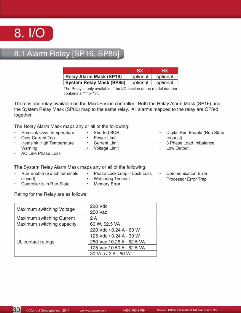
8. I/O8.1 Alarm Relay [SP16, SP85]
SX HXRelay Alarm Mask (SP16) optional optionalSystem Relay Mask (SP85) optional optional
There is one relay available on the MicroFusion controller. Both the Relay Alarm Mask (SP16) and the System Relay Mask (SP85) map to the same relay. All alarms mapped to the relay are OR’ed together.
The Relay Alarm Mask maps any or all of the following:
The Relay is only available if the I/O section of the model number contains a “1” or “3”.
• Heatsink Over Temperature• Over Current Trip• Heatsink High Temperature
Warning• AC Line Phase Loss
• Shorted SCR• Power Limit• Current Limit• Voltage Limit
• Digital Run Enable (Run State request)
• 3 Phase Load Imbalance• Low Output
The System Relay Alarm Mask maps any or all of the following:• Run Enable (Switch terminals
closed)• Controller is in Run State
• Phase Lock Loop – Lock Loss• Watchdog Timeout• Memory Error
• Communication Error• Processor Error Trap
Rating for the Relay are as follows:
Maximum switching Voltage 220 Vdc250 Vac
Maximum switching Current 2 AMaximum switching capacity 60 W, 62.5 VA
UL contact ratings
220 Vdc / 0.24 A - 60 W125 Vdc / 0.24 A - 30 W250 Vac / 0.25 A - 62.5 VA125 Vac / 0.50 A - 62.5 VA30 Vdc / 2 A - 60 W

31© Control Concepts Inc., 2014www.ccipower.com 1-800-765-2799MicroFUSION Operator’s Manual Rev 2.33
8.2 General Purpose InputSX HX
Pin 10 functionality of P1 connector optional optional
The General Purpose Input uses pins 8 and 10 of the P1 connector. When using this feature the General Purpose Input Function (SP133) must be defined. When pin 10 is pulled low (connected to pin 8) the controller will toggle the function defined in the General Purpose Input Function parameter.
8.3 General Purpose Input Function [SP133]Opening and closing the connection between pin 8 & pin 10 of the P1 connector toggles:
[SP133] Function Possible Settings See this parameter for reference
Control Setpoint Select Setpoint 1Setpoint 2 Control Setpoint Select (SP104)
Open/Closed Loop Open LoopClosed Loop Control Mode (SP3)
Other selections may be available. Contact factory for special requests.
8.4 Pulse Width Modulation InputA pulse width modulation signal may be used as a setpoint. The signal must be connected to Analog SP1 to function. The setpoint source [SP102] or [SP103] must also be set to PWM input.
Input Range:20 Hz ≤ Frequency ≤ 2 kHz0 - 5 Vdc maximum
8.5 RetransmitsSX HX
Retransmit 1 N/A optionalRetransmit 2 N/A optional
The Retransmits are configured similarly to the analog inputs. The two Retransmits can be configured independently as either a current source (0 – 20 mA) or as a voltage source (0 – 10 Vdc). The Retransmits may be mapped to Load Voltage, Current or Power. It can also be set to a direct out signal.
The General Purpose Input is only available if the I/O section of the model number contains a “2” or “3”.
The Retransmits are only available if the Retransmits section of the model number contains an “R”.

© Control Concepts Inc., 2014 www.ccipower.com 1-800-765-279932 MicroFUSION Operator’s Manual Rev 2.33
9. CCI LINK TM
This is a proprietary deterministic digital bus that enables multiple Control Concepts devices to communicate with each other.
9.1 Network LED Indicators The CCI Link™ connector has 4 LEDs, 2 yellow and 2 green. There is one LED in each corner of the connector. The Network LED indicators use the yellow and green LED located closest to the heatsink of the controller. The yellow LED opposite of the heatsink is not used. The green LED is used in the Auto Terminating Resistor Circuit.
Network State Green Yellow DescriptionNon-existent OFF OFF InitializingOn-Line Unallocated Flashing OFF No connectionsOn-Line Allocated ON OFF Connection established, OKWait-4-who’s there OFF Blink (5 sec intrvl) Not on the network, waitingIdentify X OFF-Flash-OFF Response to Identify requestTimeout ON ON Connection timed outComm Fault OFF ON Bus-OFF, DUP MAC failure
X = don’t care, or same state as before is maintained When the controller does not detect any other devices on the CCI Link™ network the green LED will be OFF and the yellow LED will flash every 5 seconds.
The yellow network LED is also used to identify a specific controller on the CCI Link™ network. When a controller is commanded to identify itself, the yellow network LED will flash 5 times.
9.2 Auto Terminating Resistor CircuitWhen connecting multiple devices on the CCI Link™ network, a terminating resistor must be pulled in at each end of the network tree. With the Auto Terminating Resistor Circuit the device automatically determines if the resistor needs to be pulled in based on if it is connected to one or two devices. When the resistor is pulled in the green LED on the CCI Link™ connector furthest away from the heatsink will be illuminated.

33© Control Concepts Inc., 2014www.ccipower.com 1-800-765-2799MicroFUSION Operator’s Manual Rev 2.33
9.3 SYNC-GUARDTM The SYNC-GUARD™ feature reduces the possibility of synchronous operation of two or more zero cross controllers. This feature does not alter the power applied to the load, but adjusts the time when power is applied in such a manner as to reduce the possibility of two or more controllers being ON and OFF in unison.
SYNC-GUARD™ is useful whenever there are two or more power controllers connected to the same power source with a zero-cross firing mode selected. The SYNC-GUARD™ feature can significantly reduce the peak current required from a source that is connected to multiple power controllers while all are zero cross firing.
Zero cross firing is an ON-OFF type of control where the desired voltage, current, or power is delivered to the load by varying the controller’s ON-OFF duty cycle. With zero cross firing, when the controller’s output is ON, full supply voltage and current are provided to the load.
Without SYNC-GUARD™, multiple zero cross firing controllers could potentially be ON and OFF all at the same time. This would require heavy current to be drawn from the source while the controllers are all ON and no current when they are all OFF. The SYNC-GUARD™ feature works to reduce the peak current draw required from the source over time by causing each controller to attempt to find a time to turn ON when fewer, or no other, controllers are firing.
LimitationsAs stated before: the SYNC-GUARD™ feature works to reduce the peak current draw required from the source for multiple controllers over time. However, each controller cannot predict when another controller is going to fire. Therefore the probability of multiple controllers firing at the same time exists even when using the SYNC-GUARD™ feature. The probability of this happening is highest when many controllers transition into the RUN state, and therefore turn ON at the same time. It is recommended that no more than 10 controllers be linked together with SYNC-GUARD™ over CCI Link™.
The figures below show the total current as a function of time for three controllers, with, and without SYNC-GUARD™ and various load powers. When using the SYNC-GUARD™ feature, the current command signals must be isolated from each other. To set up the SYNC-GUARD™ feature, see the Installation manual.
CONTROLLER#1 - ON
CONTROLLER#3 - ON
CONTROLLER#2 - ON
AM
PS
TIME
CONTROLLER#3 - ON
CONTROLLER#2 - ON
CONTROLLER#1 - ON
AM
PS
TIME
CONTROLLER#1 - ON
CONTROLLER#3 - ON
CONTROLLER#2 - ON
TIME
AM
PS
Three controllers providing 33.3% power each, operating synchronously without SYNC-GUARD™
Three controllers providing 33.3% power each, with SYNC-GUARD™
Three controllers with SYNC-GUARD™, two providing 33.3% power & one providing 66.6% power.
© Control Concepts Inc., 2014 www.ccipower.com 1-800-765-279934 MicroFUSION Operator’s Manual Rev 2.33
9.4 External Fieldbus ModuleThe external fieldbus module connects to other Control Concepts devices over the CCI Link™ bus.
See Fieldbus Module in the Accessories Section of this manual for more details.

35© Control Concepts Inc., 2014www.ccipower.com 1-800-765-2799MicroFUSION Operator’s Manual Rev 2.33
Figure 1
10. ACCESSORIES10.1 CCI Link™ CablesAvailable cable lengths: 6 inch cable – 0058003-0050-005 1 foot cable – 0058003-0050-01 5 foot cable – 0058003-0050-05 10 foot cable – 0058003-0050-10 15 foot cable – 0058003-0050-15
10.2 Fieldbus ModuleThe Fieldbus Module has any one of the following fieldbus interfaces: EtherCAT, EtherNet/IP, DeviceNet, Modbus RTU (RS-485), Modbus TCP, or PROFINET. Powered from the CCI Link™ bus, it can interface with up to 10 Control Concept devices. Each device must be given a unique MAC ID. All controllers can send or receive data over the CCI Link™ bus via one IP address. From the fieldbus interface, configurations may be saved and loaded. Performance and data logging are available with the use of a Real Time Clock and Calander (RTCC). The Fieldbus Module also takes advantage of the Auto Termination Resistor Circuit. Electrical Characteristics: 24 Vdc input power (via CCI Link™ bus) 100 mA maximum draw 3000 Vdc isolation
10.3 Remote DisplayEasily view and customize limits, setpoints, and alarm conditions 2-Line, 16-character text display (Figure 1)UL-type 1 & 12 ratings, IP65
See Appendix C for Remote Display setup and operation instructions
10.4 Din Rail Power Supplies Ratings: 85-264 Vac input, +24 Vdc output
24 Watt – 0091011-0024-160 Watt – 0091011-0060-196 Watt – 0091011-0096-1
10.5 USB Cable 15 foot, A to Micro B – 0058006-0000-15

© Control Concepts Inc., 2014 www.ccipower.com 1-800-765-279936 MicroFUSION Operator’s Manual Rev 2.33
APPENDIX A: SPECIFICATIONSPERFORMANCE
Standard High Performance OptionSetpoint Resolution 10,000 counts Selectable 10,000 or 64,000 countsInternal Control Loop Resolution 16,000 counts 64,000 countsOutput Resolution 12,000 counts @ 50Hz, 10,000 counts @
60Hz50,000 counts @ 50Hz, 42k,000 counts @ 60Hz
Accuracy (Full Conduction) Voltage 3% of span 0.5% of span Current 3% of span 0.5% of span Power 3% of span 1% of spanOutput Linearity 4% from 5 to 100% output range 1% from 5 to 100% output rangeAccuracy A +10% to -15% line voltage change will result
in a max output change of 0.5% from 5 to 100% output range
A +10% to -15% line voltage change will result in a max output change of 0.05% from 5 to 100% output range
Temperature Drift Output shall not change greater than 0.5% per degree C max over the operating temperature range from 5 to 100% output range
Output shall not change greater than 0.2% per degree C max over the operating temperature range from 5 to 100% output range
POWERLine Voltage (Auto Ranging) 24 - 600 Vac (Nominal) +10% / -15% (Contact factory for other options)Line Frequency (Auto Ranging) 45 - 65 HzFrame Current Ratings (Amps) I Continuous RMS (AC) 16 | 32 | 50 | 80
Current Rating- Peak Surge 20X frame ratingMinimum Hold/Latch Current 500 mASCR Rating (PIV) 1600 V peak forward & reverseFusing Optional external Class T, branch-rated, touch-safe fusingThermal Integrated heat sink thermal sensorCurrent Limit 20% – 105% of continuous rating of Frame Amp RatingCurrent Trip 50% - 450% of continuous ratingPower Dissipation 1.3 Watt per amp of load current per phaseControl Power / Operates Internal Control Electronics 24 Vdc +10 / -15%
ENVIRONMENTALSurrounding Air Operating Temperature 32°F [0°C] - 122°F [50°C] with no derating
32°F [0°C] - 140°F [60°C] with current derating 140°F [60°C] 16A Frame = 16A Max Output 140°F [60°C] 32A Frame = 25A Max Output 140°F [60°C] 50A Frame = 40A Max Output 140°F [60°C] 80A Frame = 60A Max Output
Humidity 20% to 90% RH Non-CondensingRated Operating Altitude Up to 6000 ft [1750m] at full rated currentContaminates ROHS Compliant, CE Pollution Degree 2Storage Temperature - 4 to 176°F [- 20 to 80°C]

37© Control Concepts Inc., 2014www.ccipower.com 1-800-765-2799MicroFUSION Operator’s Manual Rev 2.33
ISOLATIONSignal to Line/Load 3750 Vac minimumLine/Load to Ground 2500 Vac minimumSignal to Ground 1500 Vac minimumLine to Load 1400 Vac minimumNetwork 1500 Vac minimumUSB 2500 Vac minimumSignal to Processor 1500 Vac minimumRemote Display 2500 Vac minimum
DC POWER CONSUMPTION16 - 50 Amp Single Phase 9 Watts80 Amp Single Phase 11 Watts16 - 80 Amp Three Phase 24 Watts
ENCLOSURE PROTECTIVE RATINGInternational IP 20Remote Display IP 65, UL Type 1 & 12
RELIABILITY Mean Time Between Failure (MTBF) Designed for 50,000 Hours
SCCRFrame 1 Ø or 3 Ø Recommended Fusing SCCR Rating16 20 Fast Acting J or T 100 kA32 40 Fast Acting J or T 100 kA50 60 Fast Acting J or T 100 kA80 100 Fast Acting J or T 100 kA
COOLING1Ø - 16 -50 Amp Natural Convection1Ø - 80 Amp Forced Air with 1 fan PN 1608VL-05W-B603Ø - Din Rail Forced Air with 1 fan PN 3100KL-05W-B603Ø - Liquid Cooled Flow rate: 1 GPM [3.79 LPM]
Maximum inlet temperature: 122° F [30° C] Maximum pressure: 60 PSI [4.137 Bar]
3Ø - External Panel Mount Natural convection
All controllers have 100kA when using less than or equal to 100 Amp class J or T fuses. Installed in enclosure with two latches, 150% of controller size.
Control Concepts recommends sizing fuses approximately 125% frame rating.

© Control Concepts Inc., 2014 www.ccipower.com 1-800-765-279938 MicroFUSION Operator’s Manual Rev 2.33
APPENDIX B: DIGITAL FIELDBUS
TO BE DETERMINED
39© Control Concepts Inc., 2014www.ccipower.com 1-800-765-2799MicroFUSION Operator’s Manual Rev 2.33
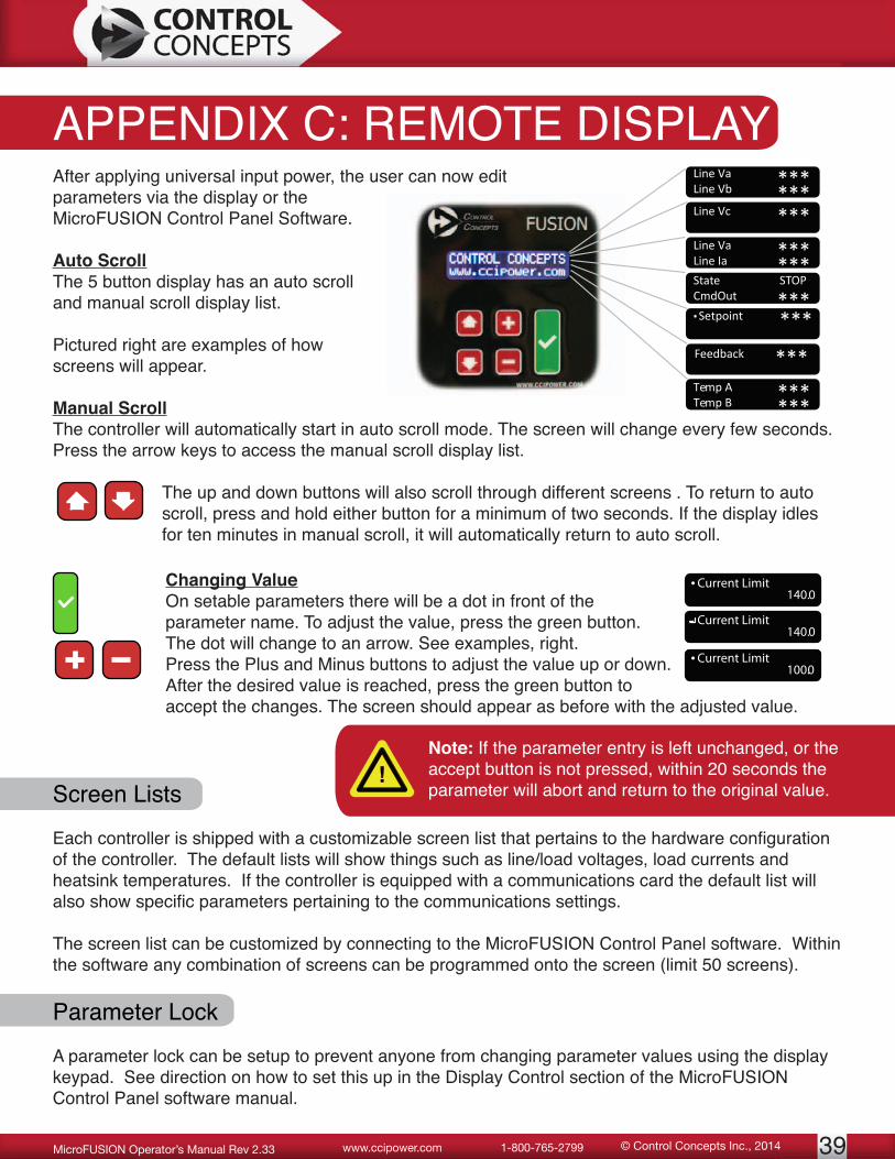
APPENDIX C: REMOTE DISPLAYAfter applying universal input power, the user can now edit parameters via the display or the MicroFUSION Control Panel Software.
Auto ScrollThe 5 button display has an auto scroll and manual scroll display list.
Pictured right are examples of how screens will appear.
Manual ScrollThe controller will automatically start in auto scroll mode. The screen will change every few seconds. Press the arrow keys to access the manual scroll display list.
The up and down buttons will also scroll through different screens . To return to auto scroll, press and hold either button for a minimum of two seconds. If the display idles for ten minutes in manual scroll, it will automatically return to auto scroll.
Te
Line Vc ***
Line VaLine Vb ***
***
Setpoint ***.
Feedback ***Temp ATemp B ***
***
Line VaLine Ia ***
***State STOPCmdOut ***
Current Limit.140.0
Current Limit140.0
Current Limit.100.0
Changing ValueOn setable parameters there will be a dot in front of the parameter name. To adjust the value, press the green button. The dot will change to an arrow. See examples, right.Press the Plus and Minus buttons to adjust the value up or down. After the desired value is reached, press the green button to accept the changes. The screen should appear as before with the adjusted value.
Screen Lists
Each controller is shipped with a customizable screen list that pertains to the hardware configuration of the controller. The default lists will show things such as line/load voltages, load currents and heatsink temperatures. If the controller is equipped with a communications card the default list will also show specific parameters pertaining to the communications settings.
The screen list can be customized by connecting to the MicroFUSION Control Panel software. Within the software any combination of screens can be programmed onto the screen (limit 50 screens).
Parameter Lock
A parameter lock can be setup to prevent anyone from changing parameter values using the display keypad. See direction on how to set this up in the Display Control section of the MicroFUSION Control Panel software manual.
Note: If the parameter entry is left unchanged, or the accept button is not pressed, within 20 seconds the parameter will abort and return to the original value.

© Control Concepts Inc., 2014 www.ccipower.com 1-800-765-279940 MicroFUSION Operator’s Manual Rev 2.33
APPENDIX D: FUSING OPTIONSAll touchsafe kits have 600 VAC, Branch-Rated, Class T Fusing
Single phase controllers require 2 Pole Fuseblocks, while Three Phase controllers require 3 Pole Fuseblocks.
Touchsafe Kits: Single Phase
MODEL NUMBER
CCI PART NUMBER AMP SIZE DESCRIPTION
F010 SFKTS62T10 10 2 Pole Assy - 2 x Fuse, 1 x Block, 2 x Cover
F015 SFKTS62T15 15 2 Pole Assy - 2 x Fuse, 1 x Block, 2 x CoverF020 SFKTS62T20 20 2 Pole Assy - 2 x Fuse, 1 x Block, 2 x Cover
F025 SFKTS62T25 25 2 Pole Assy - 2 x Fuse, 1 x Block, 2 x Cover
F030 SFKTS62T30 30 2 Pole Assy - 2 x Fuse, 1 x Block, 2 x CoverF035 SFKTS62T35 35 2 Pole Assy - 2 x Fuse, 1 x Block, 2 x CoverF040 SFKTS62T40 40 2 Pole Assy - 2 x Fuse, 1 x Block, 2 x CoverF045 SFKTS62T45 45 2 Pole Assy - 2 x Fuse, 1 x Block, 2 x CoverF050 SFKTS62T50 50 2 Pole Assy - 2 x Fuse, 1 x Block, 2 x CoverF060 SFKTS62T60 60 2 Pole Assy - 2 x Fuse, 1 x Block, 2 x CoverF070 SFKTS61T70 70 1 Pole Assy - 1 x Fuse, 1 x Block, 1 x Cover (2 required)F080 SFKTS61T80 80 1 Pole Assy - 1 x Fuse, 1 x Block, 1 x Cover (2 required)F090 SFKTS61T90 90 1 Pole Assy - 1 x Fuse, 1 x Block, 1 x Cover (2 required)F100 SFKTS61T100 100 1 Pole Assy - 1 x Fuse, 1 x Block, 1 x Cover (2 required)
Touchsafe Kits: Three Phase
MODEL NUMBER
CCI PART NUMBER AMP SIZE DESCRIPTION
F010 SFKTS63T10 10 3 Pole Assy - 3 x Fuse, 1 x Block, 3 x CoverF015 SFKTS63T15 15 3 Pole Assy - 3 x Fuse, 1 x Block, 3 x CoverF020 SFKTS63T20 20 3 Pole Assy - 3 x Fuse, 1 x Block, 3 x CoverF025 SFKTS63T25 25 3 Pole Assy - 3 x Fuse, 1 x Block, 3 x CoverF030 SFKTS63T30 30 3 Pole Assy - 3 x Fuse, 1 x Block, 3 x CoverF035 SFKTS63T35 35 3 Pole Assy - 3 x Fuse, 1 x Block, 3 x CoverF040 SFKTS63T40 40 3 Pole Assy - 3 x Fuse, 1 x Block, 3 x CoverF045 SFKTS63T45 45 3 Pole Assy - 3 x Fuse, 1 x Block, 3 x CoverF050 SFKTS63T50 50 3 Pole Assy - 3 x Fuse, 1 x Block, 3 x CoverF060 SFKTS63T60 60 3 Pole Assy - 3 x Fuse, 1 x Block, 3 x CoverF070 SFKTS63T70 70 3 Pole Assy - 3 x Fuse, 1 x Block, 3 x CoverF080 SFKTS63T80 80 3 Pole Assy - 3 x Fuse, 1 x Block, 3 x CoverF090 SFKTS63T90 90 3 Pole Assy - 3 x Fuse, 1 x Block, 3 x CoverF100 SFKTS63T100 100 3 Pole Assy - 3 x Fuse, 1 x Block, 3 x Cover

41© Control Concepts Inc., 2014www.ccipower.com 1-800-765-2799MicroFUSION Operator’s Manual Rev 2.33
APPENDIX E: 1Ø PART NUMBERSBoard Type SX = Standard HX = High performance Terminal T = Pluggable terminal block R = Ring terminal1Frame Style A = 16 - 32A (Panel Mount / DIN Rail) B = 50 - 80A (Panel Mount / DIN Rail)Option Board 0 = None E = Modbus TCP I = EtherNet/IP N = PROFINETAmp Size 16 = 16 Amps 50 = 50 Amps 32 = 32 Amps 80 = 80 AmpsPerformance Available with SX: S = Standard L = Adjustable Current Limit and current feedback Available with HX: L = Adjustable Current Limit, current feedback, load voltage feedback, & voltage limit P = High Performace (Includes Load Voltage Feedback, True RMS Power Control, Current Limit, Power Limit, High Resolution Control Loop) I/O 0 = None (Only applicable for SX; HX board is equipped with an alarm relay by default) 1 = Alarm Relay (1x Form C) 2 = General Purpose Input / Analog Input Channel 2 / Pulse Width Modulation Input 3 = Both Retransmits 0 = None R = Retransmits2 (Two 16-bit analog retransmits for voltage, current, or power)Sync 0 = None S = Digital SYNC-GUARD™Zero Cross Transformer Mode 0 = None Z = Zero Cross Transformer Mode2
Branch Rated Class T Fuse Options Blank = None F010 = 10A F035 = 35A F070 = 70A F015 = 15A F040 = 40A F080 = 80A F020 = 20A F045 = 45A F090 = 90A F025 = 25A F050 = 50A F100 =100A F030 = 30A F060 = 60A See “Fusing Options,” page 7, for more information.1 Contact factory for availability2 Only available with HX type board
uF1 - - -

© Control Concepts Inc., 2014 www.ccipower.com 1-800-765-279942 MicroFUSION Operator’s Manual Rev 2.33
APPENDIX E: 3Ø PART NUMBERSuF3 - - -
Board Type SX = Standard HX = Upgradable High PerformanceLoad Configuration 4DY = Three Phase 4 SCR (2 Leg) 6DY = Three Phase Delta/Wye, 6 SCR 64Y = Three Phase 4 Wire Wye, 6 SCR 6ID = Three Phase Inside Delta, 6 SCRFrame A = 16 - 32A (Panel Mount / Din Rail) B = 50 - 80A (Panel Mount / Din Rail) C = 16 - 32A (External Mount) 1
D = 50A (External Mount) 1
E = 16 - 32A (Liquid Cooled) 1
F = 50 - 80A (Liquid Cooled) 1
Option Board 0 = None E = Modbus TCP I = EtherNet/IP N = PROFINETAmp Size 16 = 16 Amps 50 = 50 Amps 32 = 32 Amps 80 = 80 Amps 2Performance Available with SX: S = Standard L = Adjustable Current Limit and current feedback Available with HX: L = Adjustable Current Limit, current feedback, load voltage feedback, & voltage limit P = High Performace (Includes Load Voltage Feedback, True RMS Power Control, Current Limit, Power Limit, High Resolution Control Loop) I/O 0 = None (Only applicable for SX; HX board is equipped with an alarm relay by default) 1 = Alarm Relay (1x Form C) 2 = General Purpose Input / Analog Input Channel 2 / Pulse Width Modulation Input 3 = Both Retransmits 0 = None R = Retransmits 3 (Two 16-bit analog retransmits for voltage, current, or power)Sync 0 = None S = Digital SYNC-GUARD™Zero Cross Transformer Mode Z = Zero Cross Transformer Mode 3
Branch Rated Class T Fuse Options Blank = None F010 = 10A F035 = 35A F070 = 70A F015 = 15A F040 = 40A F080 = 80A F020 = 20A F045 = 45A F090 = 90A F025 = 25A F050 = 50A F100 =100A F030 = 30A F060 = 60A See “Fusing Options,” page 7, for more information.1 UL pending2 80 Amps not available for external panel mount3 Only available with HX type board