1. project mission and target market design mission and requirements walk-around sizing code...
TRANSCRIPT
1
Conceptual Design Review
Dean Jones
Dustin Souza
Anthony Malito
Ricardo Mosqueda
Alex Fickes
Keyur Patel
Matt Dienhart
Danielle Woehrle
Nayanapriya Bohidar
N.E.R.D.New Environmentally Responsible Design

• Project Mission and Target Market
• Design Mission and Requirements
• Walk-around
• Sizing code Description
• Carpet Plots
• Aircraft Description
• Aerodynamic details
• Performance
• Propulsion
• Structures
• Weights and Balance
• Stability and Control
• Noise
• Cost
• Summary
Outline
2

• Mission Statement
– “To design an environmentally responsible aircraft for the twin aisle
commercial transport market with a capacity of 300+ passengers, NASA’s
N+2 capabilities, and an entry date of 2020-2025.”
– NASA’s N+2 technology requirements include:
1. Reducing cumulative noise by 42dB below Stage 4
2. Reducing take-off and landing NOx emissions to 75% below CAEP6 levels
3. Reducing fuel burn by 50% relative to “large twin-aisle performance” (777-200LR)
4. Reducing field length by 50% relative to the large twin-aisle
Project Mission
3

• Mission Statement
– A high-capacity, short- to
medium-haul aircraft
– Primarily servicing Asia-
South Pacific region
Target Market
4

Target Market
5
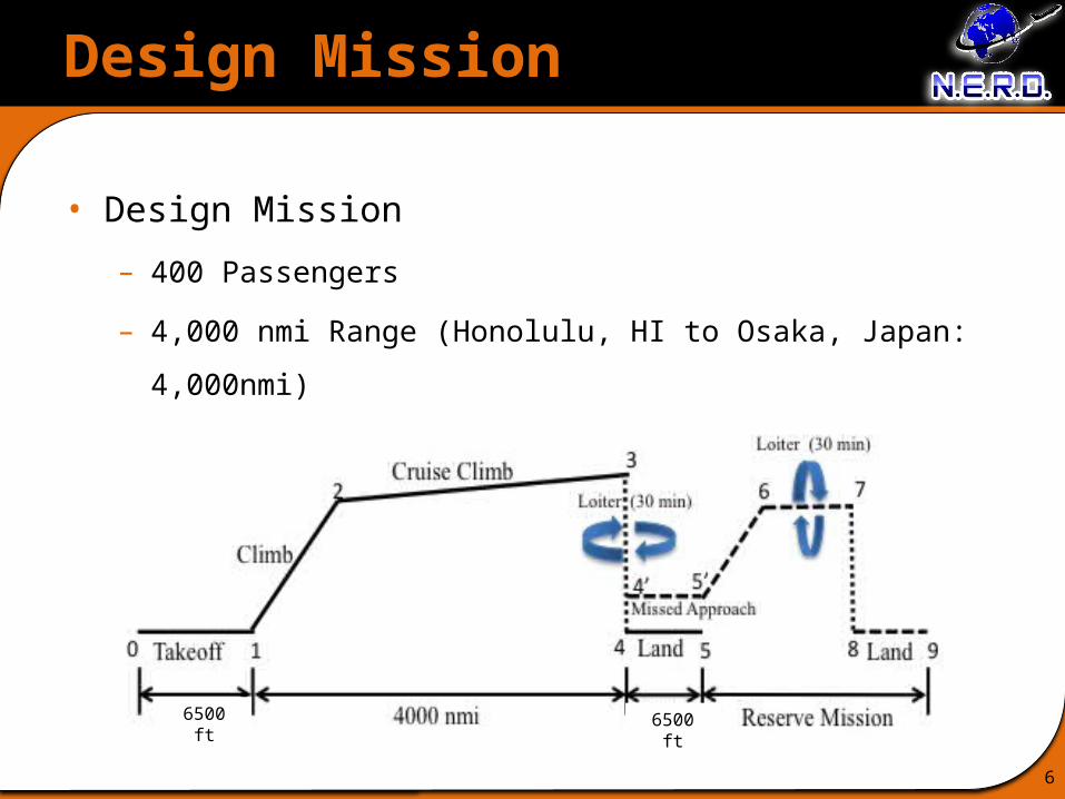
Design Mission
6
• Design Mission
– 400 Passengers
– 4,000 nmi Range (Honolulu, HI to Osaka, Japan: 4,000nmi)
6500 ft 6500 ft

Design Requirements
7
Requirements Threshold Target
Cruise Mach 0.75 0.80
Range 3,000 nmi 4,000 nmi
Field Length(at sea level, MTOW) 8,800 ft 5,800 ft
Field Length(@ 14K ft, +15°F) 18,000 ft 9,000 ft
Fuel Burn* 33% reduction 50% reduction**
NOx Emissions 50% below CAEP 6 75% below CAEP 6**
Noise Reduction 32 EPNdB cum. below Stage 4
42 EPNdB cum. below Stage 4**
Passenger Capacity 350 400
Direct Operating Cost* 10% Reduction 15% Reduction
*Relative to B777-200LR** NASA ERA goal
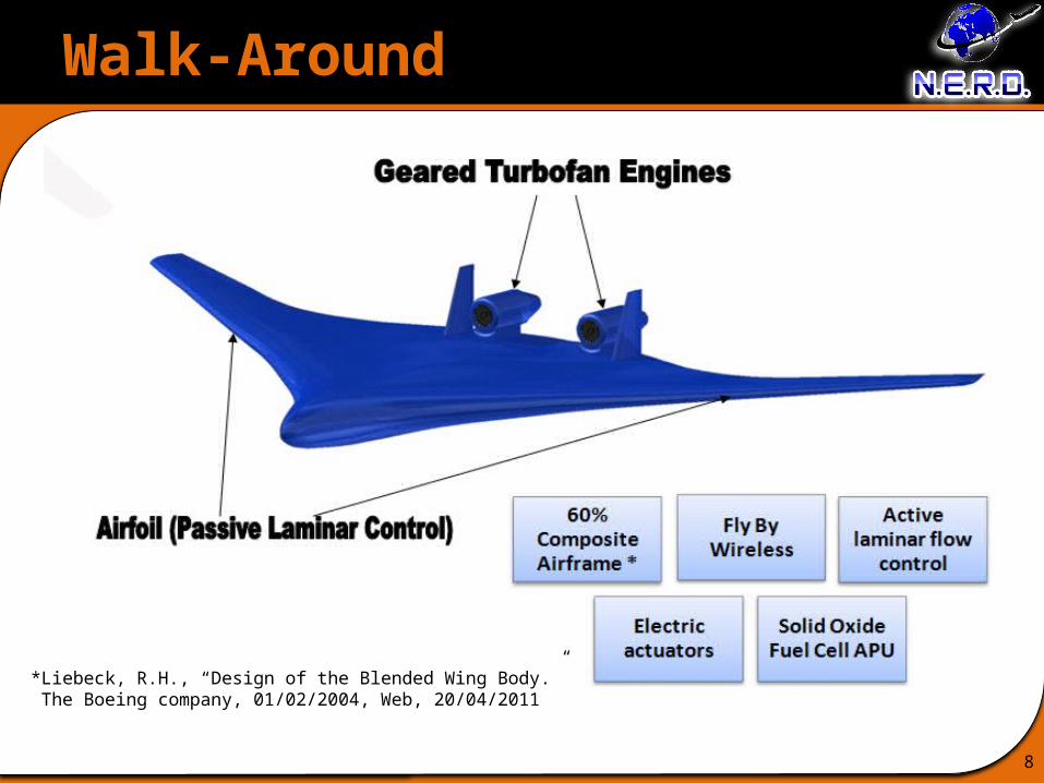
Walk-Around
8
*Liebeck, R.H., “Design of the Blended Wing Body.” The Boeing company, 01/02/2004, Web, 20/04/2011
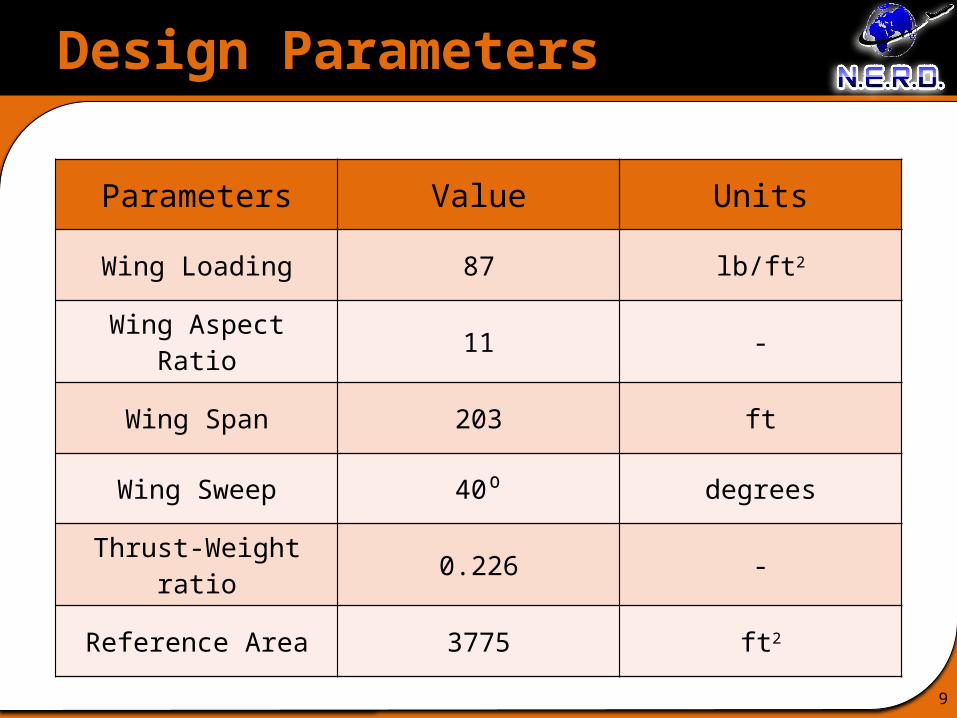
Design Parameters
9
Parameters Value Units
Wing Loading 87 lb/ft2
Wing Aspect Ratio 11 -
Wing Span 203 ft
Wing Sweep 40⁰ degrees
Thrust-Weight ratio 0.226 -
Reference Area 3775 ft2

Technologies
10
Requirements GTF Composites
WingtipTechnolo
gy
FlyBy
Wireless
TrailingEdge
Brushes
ElectricActuator
s
LaminarFlow
Control
Active Noise
Cancellation
Fuel Burn + + + + - + +
Exterior Noise + + + + +
NOX +
Field Length
Empty Weight - + - + - + - -
Cruise Speed
Manufacturing Cost - - - - - -
Maintenance Cost - - + - + - -
Pax/Crew Comfort + +
Layout Complexity - - - -
Stability & Maneuverability
Minimum Ground Time
Aesthetics + + - -
Sigma 1 1 0 2 -4 3 -2 -3
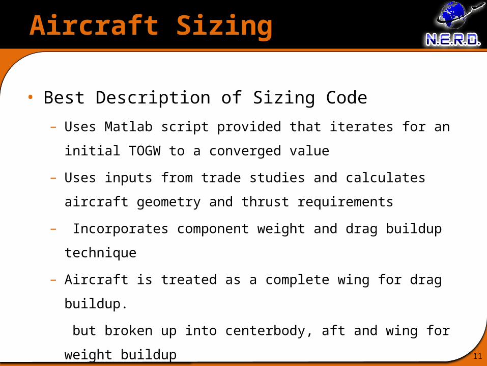
Aircraft Sizing
11
• Best Description of Sizing Code
– Uses Matlab script provided that iterates for an initial TOGW to a
converged value
– Uses inputs from trade studies and calculates aircraft geometry and thrust
requirements
– Incorporates component weight and drag buildup technique
– Aircraft is treated as a complete wing for drag buildup.
but broken up into centerbody, aft and wing for weight buildup

Aircraft Sizing
12
• Fixed Design Parameter Values
Parameter Value Units
1. Taper ratio 0.27 -
2. Sweep 40 degrees
3. CLmax 1.4 -
4. Vpr 85,500 ft3
5. Max Landing weight fraction 0.9 -
6. Passenger weight 88000 lbs
7. Crew weight 1400 lbs

Aircraft Sizing
13
• Modeling Approaches– Weight Equations: Raymer’s Transport equations + NASA Sizing
Methodology for the Conceptual Design of BWB, by Kevin R. Bradley
Wfuse = 5.698865*0.316422(TOGW)0.16652(Scabin)1.061158
Waft = (1 + 0.05*NEng)*0.53*Saft*(TOGW)0.2*(λaft + 0.5)
Component Weight lbs1. We 17,7210
2. Wfuel 61,800
3. Wengine 7,220
4. Wcenterbody 83,910
5. Wwing 88,000
6. WVT 1,400
7. Wavionics 1,840

Aircraft Sizing
14
• Modeling Approaches (contd.)– Drag prediction equations: Raymer’s component drag buildup method
using a transonic Re cutoff, flat plate skin friction coefficient and component form factors.
– Tail sizing: Raymer’s equations + cross-wind and one-engine out conditions
Component Parasite Drag1. Cdo,wing 0.0117
2. Cdo,VT 0.0003
3. Cdo,pylons 0.0001
4. Cdo,nacelles 0.0003
Component Parasite Drag ft2
1. Sref 163
Aircraft Sizing
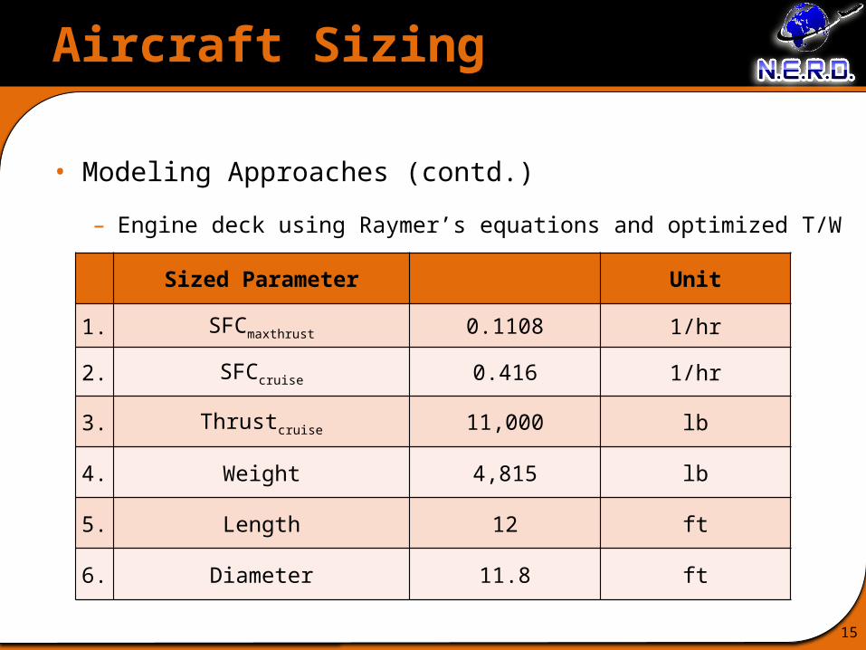
15
Sized Parameter Unit
1. SFCmaxthrust 0.1108 1/hr
2. SFCcruise 0.416 1/hr
3. Thrustcruise 11,000 lb
4. Weight 4,815 lb
5. Length 12 ft
6. Diameter 11.8 ft
• Modeling Approaches (contd.)
– Engine deck using Raymer’s equations and optimized T/W
Aircraft Sizing
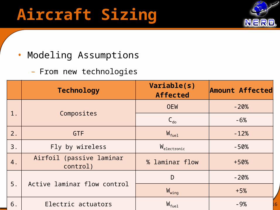
16
• Modeling Assumptions
– From new technologies
Technology Variable(s) Affected Amount Affected
1. CompositesOEW -20%
Cdo -6%
2. GTF Wfuel -12%
3. Fly by wireless Welectronic -50%
4. Airfoil (passive laminar control) % laminar flow +50%
5. Active laminar flow controlD -20%
Wwing +5%
6. Electric actuators Wfuel -9%
Aircraft Sizing
17
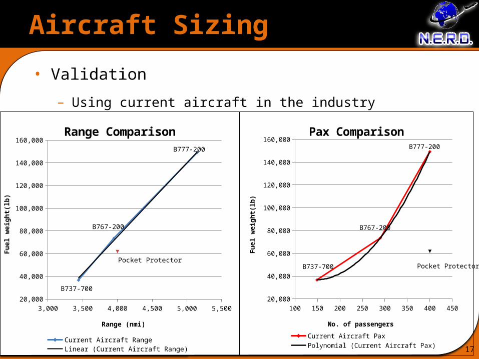
• Validation
– Using current aircraft in the industry
3,000 3,500 4,000 4,500 5,000 5,50020,000
40,000
60,000
80,000
100,000
120,000
140,000
160,000
Pocket Protector
B737-700
B767-200
B777-200
Range Comparison
Current Aircraft Range Linear (Current Aircraft Range)Pocket Protector Range
Range (nmi)
Fuel
wei
ght(
lb)
100 150 200 250 300 350 400 45020,000
40,000
60,000
80,000
100,000
120,000
140,000
160,000
Pocket ProtectorB737-700
B767-200
B777-200
Pax Comparison
Current Aircraft Pax Polynomial (Current Aircraft Pax)Pocket Protector Pax
No. of passengers
Fuel
wei
ght(
lb)
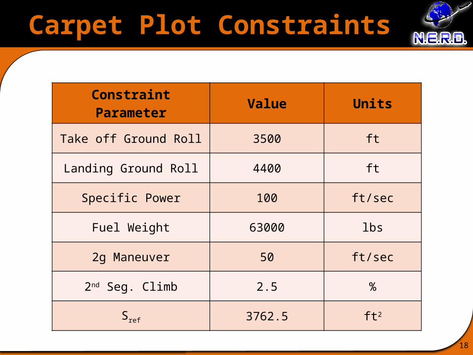
Carpet Plot Constraints
18
Constraint Parameter Value Units
Take off Ground Roll 3500 ft
Landing Ground Roll 4400 ft
Specific Power 100 ft/sec
Fuel Weight 63000 lbs
2g Maneuver 50 ft/sec
2nd Seg. Climb 2.5 %
Sref 3762.5 ft2
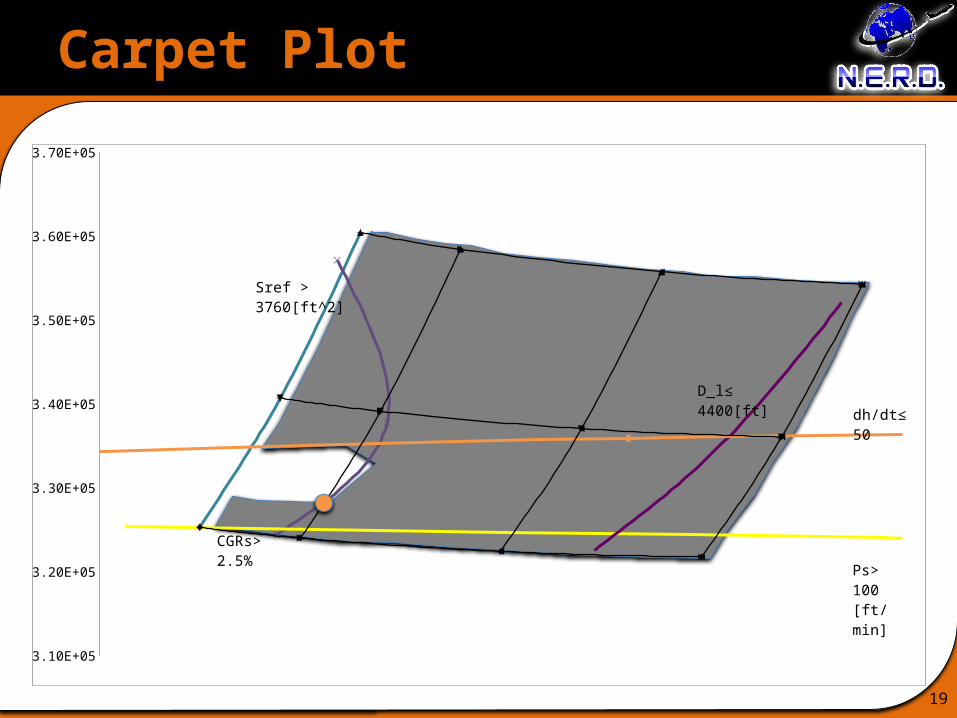
Carpet Plot
19
3.10E+05
3.20E+05
3.30E+05
3.40E+05
3.50E+05
3.60E+05
3.70E+05
D_l≤ 4400[ft]
dh/dt≤ 50
Ps> 100 [ft/min]
CGRs> 2.5%
Sref > 3760[ft^2]

Carpet Plot Results
20
Parameter VALUE Comparison NASA ERA Goals
TOGW 328410 lb -
We 177210 lb -
Wfuel 61799 lb 51% Decrease
AR 11 -
T/W 0.226 -
W/S 87 -
Cdo 0.0131 -
Sref 3775 ft2 -
Field Length 8,670 ft Does not meet NASA Field Length goals
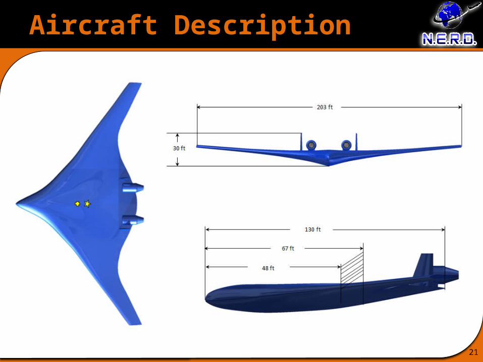
Aircraft Description
21
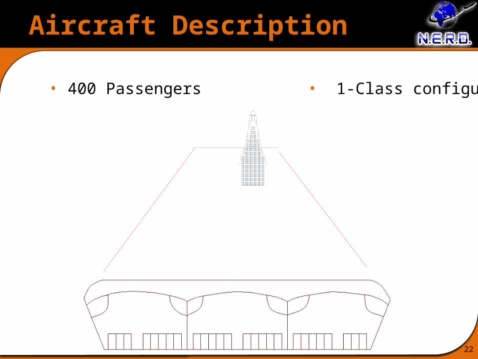
Aircraft Description
22
• 400 Passengers • 1-Class configuration

Aerodynamic Design Details
23
• Difficult to put flaps on a HWB design– must make due with leading edge high-lift devices
– Choose airfoils with high camber/high CLmax
• To reduce fuel burn, airfoil should offer minimum drag– Laminar flow airfoils (eg. NACA 6-series)
– Smooth fabrication to reduce skin friction
• Airfoil thickness chosen with respect to laminar flow properties
and structural considerations– HWB must fit entire cabin volume within the wing section
– t/c >14% desirable for good performance (gradual stall)
• Design lift coefficient is a function of wing loading 10.385L design
WC
q S
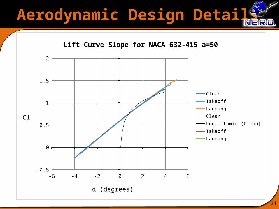
Aerodynamic Design Details
24
-6 -4 -2 0 2 4 6-0.5
0
0.5
1
1.5
2
Lift Curve Slope for NACA 632-415 a=50
CleanTakeoffLandingCleanLogarithmic (Clean)TakeoffLanding
α (degrees)
Cl
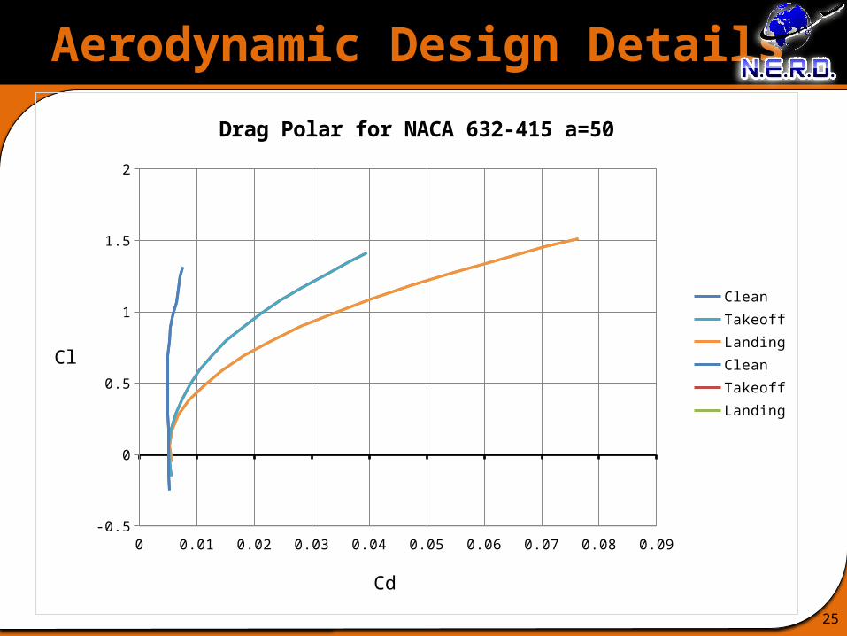
Aerodynamic Design Details
25
0 0.01 0.02 0.03 0.04 0.05 0.06 0.07 0.08 0.09-0.5
0
0.5
1
1.5
2
Drag Polar for NACA 632-415 a=50
CleanTakeoffLandingCleanTakeoffLanding
Cd
Cl

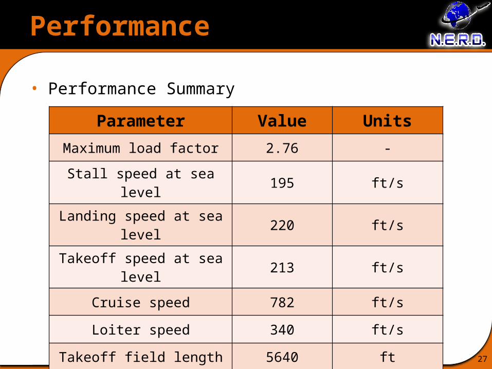
Performance
26
• V-n diagram with gust loading
Performance
27
• Performance Summary
Parameter Value Units
Maximum load factor 2.76 -
Stall speed at sea level 195 ft/s
Landing speed at sea level 220 ft/s
Takeoff speed at sea level 213 ft/s
Cruise speed 782 ft/s
Loiter speed 340 ft/s
Takeoff field length 5640 ft
Landing field length 8670 ft
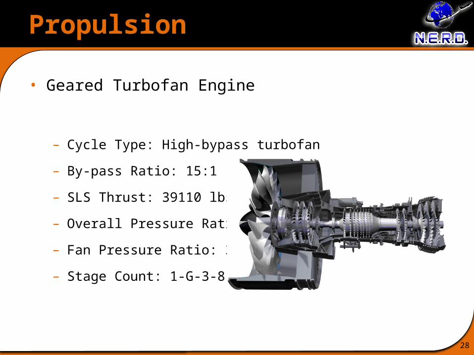
Propulsion
28
• Geared Turbofan Engine
– Cycle Type: High-bypass turbofan
– By-pass Ratio: 15:1
– SLS Thrust: 39110 lbs.
– Overall Pressure Ratio: 50:1
– Fan Pressure Ratio: 3:1
– Stage Count: 1-G-3-8-2-3
Propulsion
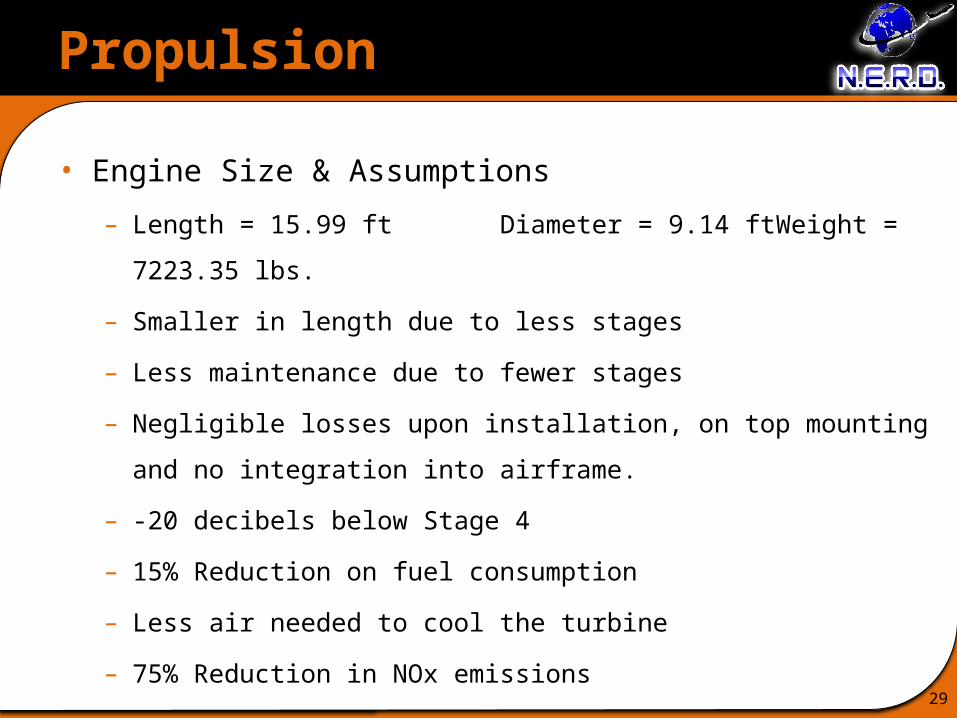
29
• Engine Size & Assumptions
– Length = 15.99 ft Diameter = 9.14 ft Weight = 7223.35 lbs.
– Smaller in length due to less stages
– Less maintenance due to fewer stages
– Negligible losses upon installation, on top mounting and no integration
into airframe.
– -20 decibels below Stage 4
– 15% Reduction on fuel consumption
– Less air needed to cool the turbine
– 75% Reduction in NOx emissions
Propulsion
30
• Engine Performance

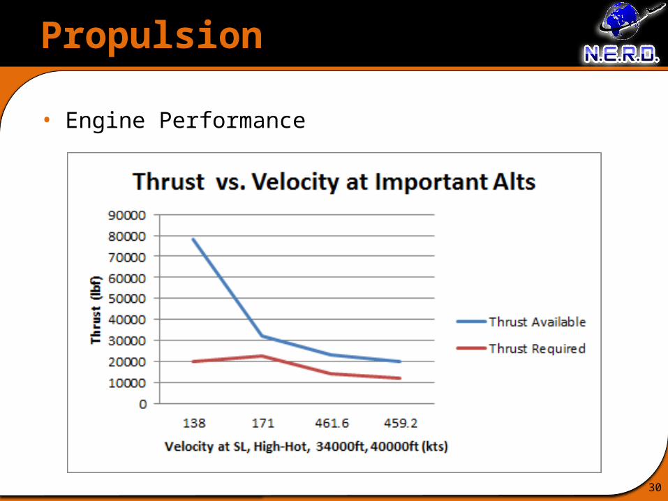
Propulsion
31
• Engine Performance (cont’d)
Important Altitudes
Velocity Desired (ft/s)
Thrust Required (lbs)
Thrust Available (lbs)
SLS – 0 ft 213 20106.9 78220High Hot – 14,000 ft 265 22417.7 32003.5
Cruise – 34,000 ft 780.104 14409.6 22994.940,000 ft 776.048 12050.6 20019.1
Single Engine PerformanceSFC at Tmax 0.111
Thrust at Cruise 11002.68SFC at Cruise 0.416
Structures
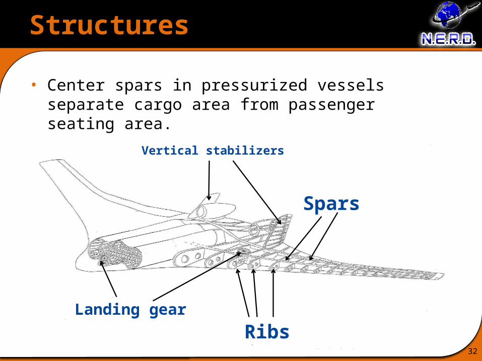
32
Spars
RibsLanding gear
Vertical stabilizers
• Center spars in pressurized vessels separate cargo area from passenger seating area.
Structures
33
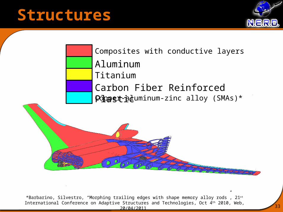
Composites with conductive layersAluminumTitaniumCarbon Fiber Reinforced PlasticCopper-aluminum-zinc alloy (SMAs)*
*Barbarino, Silvestro, “Morphing trailing edges with shape memory alloy rods”, 21st International Conference on Adaptive Structures and Technologies, Oct 4th 2010, Web, 20/04/2011
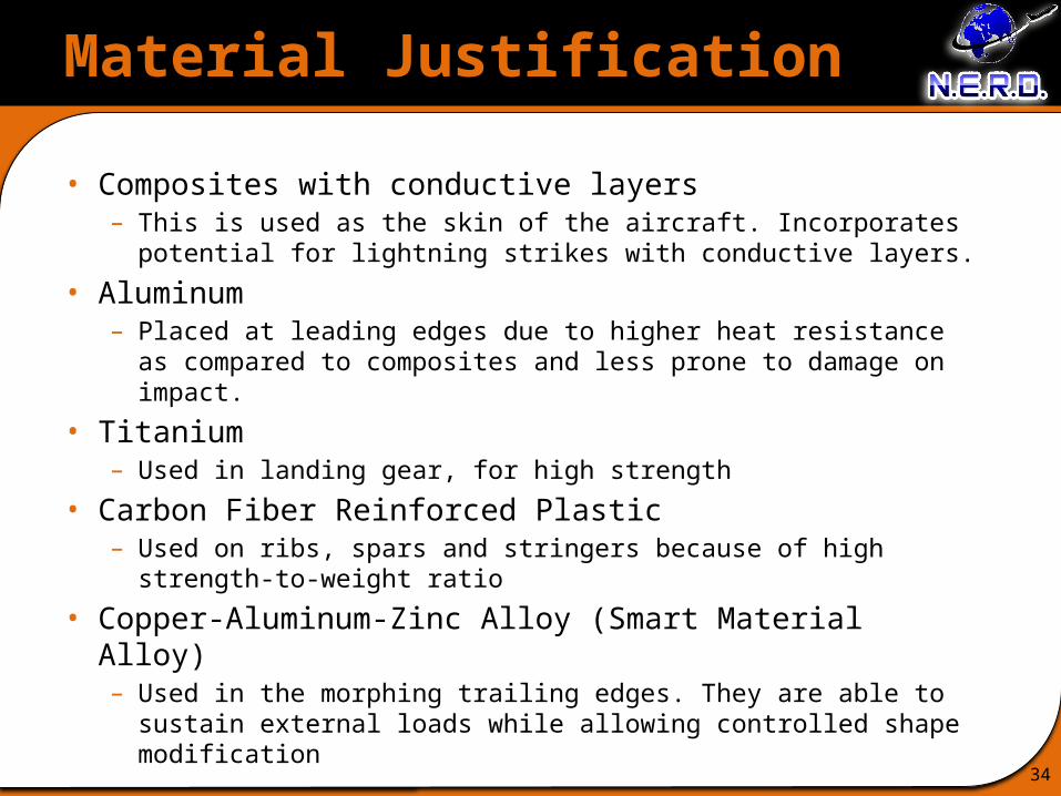
Material Justification
34
• Composites with conductive layers– This is used as the skin of the aircraft. Incorporates potential for
lightning strikes with conductive layers.
• Aluminum– Placed at leading edges due to higher heat resistance as compared to
composites and less prone to damage on impact.
• Titanium– Used in landing gear, for high strength
• Carbon Fiber Reinforced Plastic– Used on ribs, spars and stringers because of high strength-to-weight
ratio
• Copper-Aluminum-Zinc Alloy (Smart Material Alloy)– Used in the morphing trailing edges. They are able to sustain external
loads while allowing controlled shape modification
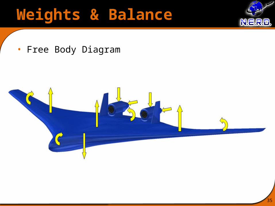
Weights & Balance
35
• Free Body Diagram
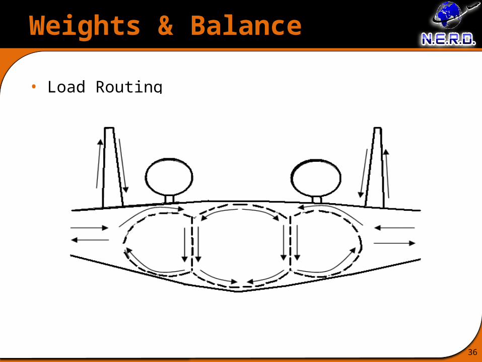
Weights & Balance
36
• Load Routing

Weights & Balance
37
• Empty Weight BreakdownWeight [lb] Weight [lb]
Structures
Wing 32441.00
Equipment
APU 2800.00
Vertical Tail 4698.00 Flight Controls 7088.40
Center Body 83910.00 Instruments 1772.10
Main Landing Gear 7766.90 Hydraulics 5316.30
Nose Landing Gear 1412.16 Electrical 8860.50
Engine Mounts 2889.36 Avionics 2362.80
Nacelles 1772.10 Furnishings 17721.00
Misc. Systems 5316.30
Propulsion
Fuel System/Tanks 2889.36
Engine Cooling 2167.02
Useful Load
Crew 1400.00
Exhaust System 1011.28 Fuel 61799.00
Starter 577.87 Oil 722.34
Passengers 72000.00
Payload 16000.00
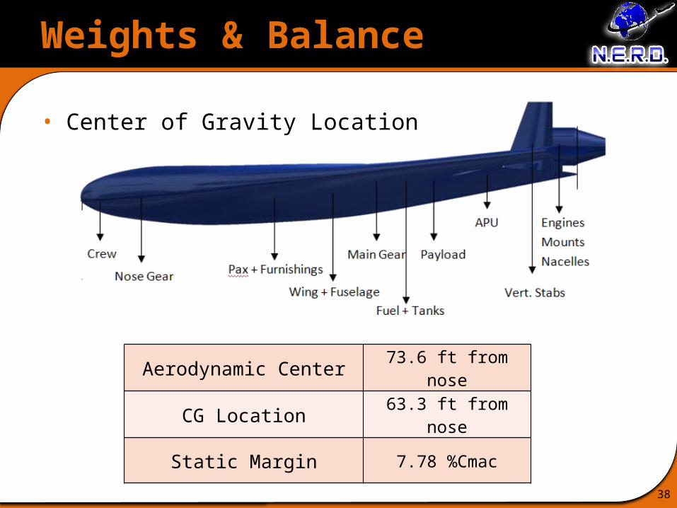
Weights & Balance
38
• Center of Gravity Location
Aerodynamic Center 73.6 ft from nose
CG Location 63.3 ft from nose
Static Margin 7.78 %Cmac

Stability & Control
39
• Lateral trim for one engine out @ V = 1.1Vstall
• Rudder deflection angle δ = 16 degrees
• Cross wind landing condition @ V = .2 VTO
• Sideslip angle β = 5 degree
Tail Surface area Tail height Rudder height Rudder width
163 ft2 each326 ft2 total 25.5 ft 15.3 ft 4.2 ft
Aileron Surface area Aileron span Aileron length
165.8 ft2 each331.70500 ft2 total 81.5 ft 2 ft

Noise
40
• Approach
– Choose baseline engine
– Adjust engine PNdB level based on:
• Distance
• Maximum thrust
• Partial throttle
• Engine technologies
– Calculate airframe noise for landing
• Function of aircraft weight

Noise
41
Noise Level BreakdownBasis of Change Change in dB
Number of engines +3.0
Maximum thrust -4.7Partial throttle during
landing -6.9
Distance during takeoff measurement -12.8
Distance during sideline measurement -5.5
Distance during approach measurement +8.8
Takeoff EPNdB adjustment -4.0
Landing EPNdB adjustment -5.0
Engine Technology -15
Baseline Engine
GE90-115B
Thrust 115,000 lbs
Noise 103 PNdBDistance to
measurement 1,107 ft

Noise
42
• FAR Noise Thresholds & Design Noise Level
Condition Stage 3 Requirement (EPNdB)
Design Noise Level (EPNdB) Margin (EPNdB)
Takeoff 95.5 69.5 26.0
Sideline 99.4 76.8 22.6
Approach 102.9 95.4 7.4
Sum 56.1
Below Stage 4 46.1
43
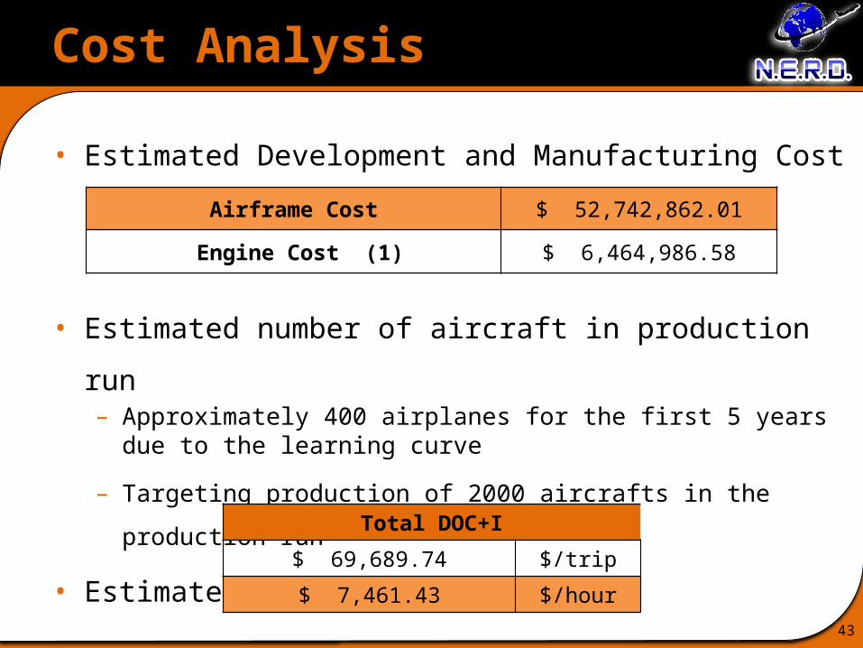
Cost Analysis
• Estimated Development and Manufacturing Cost
• Estimated number of aircraft in production run– Approximately 400 airplanes for the first 5 years due to the learning curve
– Targeting production of 2000 aircrafts in the production run
• Estimated Direct Operating Cost
Airframe Cost $ 52,742,862.01
Engine Cost (1) $ 6,464,986.58
Total DOC+I
$ 69,689.74 $/trip
$ 7,461.43 $/hour

44
Cost Analysis
• DOC + I Method
– Fuel Cost
– Flight Deck Crew Cost
– Airframe Maintenance Cost
– Engine Maintenance Cost
– Depreciation
– Interest
– Insurance
45
Cost Analysis
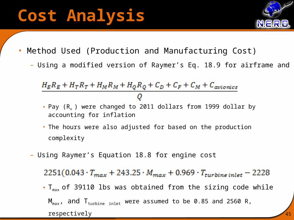
• Method Used (Production and Manufacturing Cost)
– Using a modified version of Raymer’s Eq. 18.9 for airframe and
• Pay (Rx ) were changed to 2011 dollars from 1999 dollar by accounting for
inflation
• The hours were also adjusted for based on the production complexity
– Using Raymer’s Equation 18.8 for engine cost
• Tmax of 39110 lbs was obtained from the sizing code while Mmax, and
Tturbine inlet were assumed to be 0.85 and 2560 R, respectively
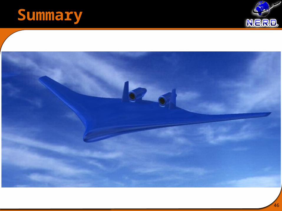
Summary
46

Compliance Matrix
47
Requirements Threshold Target Current Values
Cruise Mach 0.75 0.80 0.80
Range 3,000 nmi 4,000 nmi 4,000 nmi
Field Length(at sea level, MTOW) 8,800 ft 5,800 ft 8,670 ft
Field Length(@ 14K ft, +15°F) 18,000 ft 9,000 ft 10,500 ft
Fuel Burn* 33% reduction 50% reduction** 51% reduction
NOx Emissions 50% below CAEP 6 75% below CAEP 6** 50% reduction
Noise Reduction 32 EPNdB cum. below Stage 4
42 EPNdB cum. below Stage 4**
46.1 EPNdB cum. below Stage 4
Passenger Capacity 350 400 400
Direct Operating Cost* 10% Reduction 15% Reduction 79% Increase
*Relative to B777-200LR** NASA ERA goal
Future Work
• NOx Prediction
• Structural Refinement
• Design & Development Work
Summary
48