1 quantum software training system configuration using eaglevision-nt
TRANSCRIPT
1
Quantum Software Training
System Configuration using Eaglevision-NT
2
Eaglevision-NT Training Goals
• Load Eaglevision-NT into your OISLoad Eaglevision-NT into your OIS• Establish CommunicationsEstablish Communications• Configure and Download addressesConfigure and Download addresses• Write to EEPROMSWrite to EEPROMS• Identify all Config/Display Screen elementsIdentify all Config/Display Screen elements• Understand Network Loading ConcernsUnderstand Network Loading Concerns• Utilize Diagnostic ScreensUtilize Diagnostic Screens• Describe Custom Graphics capabilitiesDescribe Custom Graphics capabilities
3
Eaglevision-NT Software
• Eaglevision NT performs two main functions:Eaglevision NT performs two main functions:• Builds the system database (on/off line)Builds the system database (on/off line)• Configures and monitors system hardware (on line)Configures and monitors system hardware (on line)
4
EagleVision-NT Standard Software
• Basic, standalone system software packageBasic, standalone system software package• Needed to configure every Quantum systemNeeded to configure every Quantum system• Compatible with Windows95 or WindowsNTCompatible with Windows95 or WindowsNT• OIS hardware/memory requirements:OIS hardware/memory requirements:
• 133 mhz Pentium133 mhz Pentium• 64 mb ram64 mb ram
5
Eaglevision -NT for Wonderware
• Designed to run with Intouch MMI version 7.0Designed to run with Intouch MMI version 7.0• Windows-NT operating system Windows-NT operating system onlyonly• Two additional features above std. Eaglevision NT:Two additional features above std. Eaglevision NT:
• real time data exchangereal time data exchange
• tagname export functiontagname export function
• Hardware RequirementsHardware Requirements• 133 mhz Pentium133 mhz Pentium
• 64 mb ram64 mb ram
• 1024x768 pixel screen resolution1024x768 pixel screen resolution
• Intouch runtime or developers keyIntouch runtime or developers key
6
Eaglevision-NT Installation
• Load Eaglevision-NT into the OIS floppy driveLoad Eaglevision-NT into the OIS floppy drive• Using Windows Program Mgr, select Using Windows Program Mgr, select FFile, ile, RRun, and un, and
type type a:\setupa:\setup• Once installed, double-click on Quantum icon to start Once installed, double-click on Quantum icon to start
programprogram
7
Database Configuration
• Build PC Database-Build PC Database-• Select “New” from File Menu to start a new projectSelect “New” from File Menu to start a new project
• Select “Save As” from the file menu to save your projectSelect “Save As” from the file menu to save your project
• Project name should appear in window title barProject name should appear in window title bar• Completed Completed LON Listing WorksheetLON Listing Worksheet required required• All Gateway DIP switches should be set per worksheetAll Gateway DIP switches should be set per worksheet• All Logic Controller DIP switches set per worksheetAll Logic Controller DIP switches set per worksheet• All Field Device DIP switches set per worksheetAll Field Device DIP switches set per worksheet
8
Establishing Communications
• Click on “Config” under “File” menuClick on “Config” under “File” menu• Port Configuration screen will be displayedPort Configuration screen will be displayed• Select “Reset/Program” keyswitch position on Logic Select “Reset/Program” keyswitch position on Logic
Controller faceplateController faceplate• Download data to all devices by clicking on “Download All”Download data to all devices by clicking on “Download All”• Download data to a single device by clicking on Download data to a single device by clicking on
“Download One”. Start with lowest address first“Download One”. Start with lowest address first• Watch for errors such as “device not present” “wrong Watch for errors such as “device not present” “wrong
device type selected”, “invalid configuration”, or “not device type selected”, “invalid configuration”, or “not communicating”communicating”
9
Gateway Port Configuration Screen
10
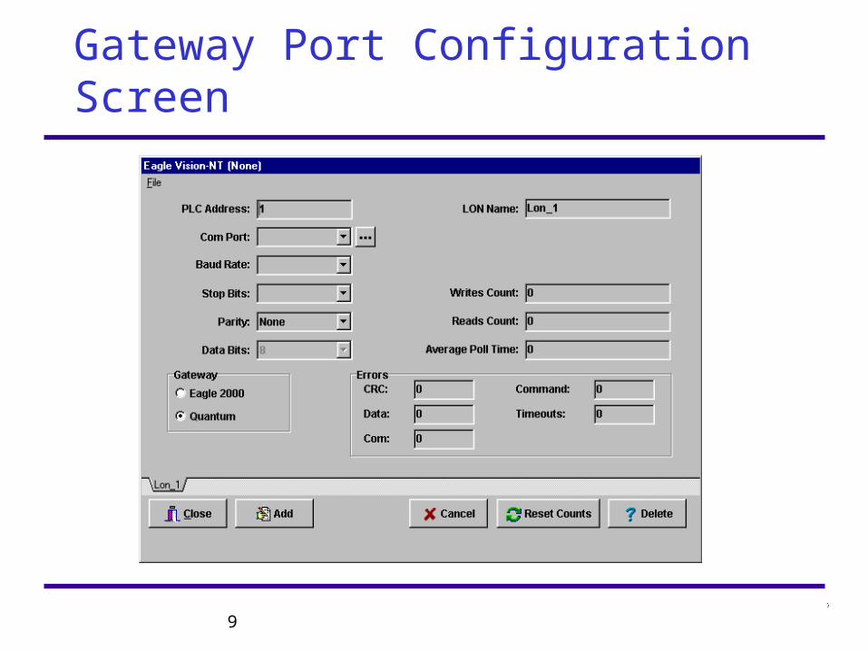
Gateway Port Configuration Screen
• Define LON network typeDefine LON network type
• Define Serial ConnectionsDefine Serial Connections
• PLC address field must match Modbus address set on the PLC address field must match Modbus address set on the GatewayGateway
• If port 1 (0 for EA2000), then address is set on DIP If port 1 (0 for EA2000), then address is set on DIP switchesswitches
• If port 2 (1 for EA2000), then address is set via software; If port 2 (1 for EA2000), then address is set via software; Default address is Port 1Default address is Port 1
• Com Port field defines which PC serial port is connected Com Port field defines which PC serial port is connected to gatewayto gateway
• Press button for auto-connectPress button for auto-connect
11
Gateway Port Configuration Screen
• Baud rate, data bits, and parity fields must match Baud rate, data bits, and parity fields must match rocker switch settings on Gatewayrocker switch settings on Gateway
• Baud rate of 19.2K recommended when using port 1Baud rate of 19.2K recommended when using port 1• If PC is connected to port 2, then 9600 baud req’dIf PC is connected to port 2, then 9600 baud req’d• One stop bit should always be usedOne stop bit should always be used• Parity setting must match rocker switch setting Parity setting must match rocker switch setting S6S6
• if port 2 is used, then parity must be evenif port 2 is used, then parity must be even
• LON name is used as prefix for HMI software tag LON name is used as prefix for HMI software tag names, so keep this name shortnames, so keep this name short
12
Configuring System Hardware
• Find “Point Configuration” screen and select addressFind “Point Configuration” screen and select address• Click on “Modify Point” buttonClick on “Modify Point” button• ““Point Not Defined” will appear. Click on “Define”Point Not Defined” will appear. Click on “Define”• Select device type and click “OK”Select device type and click “OK”• Select desire device parametersSelect desire device parameters• Repeat for each device on the systemRepeat for each device on the system• Save the projectSave the project
13
Field Node Point Configuration
• Select Point number (start w/ #10 for first device)Select Point number (start w/ #10 for first device)• Press “modify point” buttonPress “modify point” button• ““Point not defined” will be displayedPoint not defined” will be displayed• Press “Define” buttonPress “Define” button• Select device type and press OK buttonSelect device type and press OK button• Set device parametersSet device parameters• Download to device (Download All is OK for new proj)Download to device (Download All is OK for new proj)• Save the project!Save the project!
14
Gateway Relays
• Select start & end address for each relaySelect start & end address for each relay• Address block monitored by eachAddress block monitored by each• Select events to actuateSelect events to actuate• Fault relay will actuate on LON fault or internal Fault relay will actuate on LON fault or internal
gateway faultgateway fault• Select “energized” for norm. energized coilSelect “energized” for norm. energized coil• Select “Accept” commandSelect “Accept” command
15
Destination Addresses
• Logic Controller is typical node Destination AddressLogic Controller is typical node Destination Address• Logic Controller occupies two adjacent addresses, Logic Controller occupies two adjacent addresses,
always odd number always odd number first first (#5 recommended)(#5 recommended)• Will receive destination data at either addressWill receive destination data at either address• For max performance, always alternate odd & even For max performance, always alternate odd & even
addresses during system configuration addresses during system configuration • Convenient to address odd # node addresses to odd Convenient to address odd # node addresses to odd
Logic controller address, and even # nodes to even Logic controller address, and even # nodes to even Logic controller addressLogic controller address
16
Write to EEPROM’s
• When When allall devices are communicating- devices are communicating-• Select GatewaySelect Gateway• click on “Write EEPROM” to write data to gatewayclick on “Write EEPROM” to write data to gateway• Select Logic ControllerSelect Logic Controller• click on “Write EEPROM” to write data to Logic click on “Write EEPROM” to write data to Logic
ControllerController
17
Network Loading
• Gateway can handle up to 50 messages per secondGateway can handle up to 50 messages per second• For 50 node system, all can update once per secondFor 50 node system, all can update once per second• For 240 nodes, average update can be every 5 secFor 240 nodes, average update can be every 5 sec• Device update rate can be set individuallyDevice update rate can be set individually• Average update time must Average update time must notnot exceed 50 messages exceed 50 messages
per secondper second
18
Gateway Display Screen
19
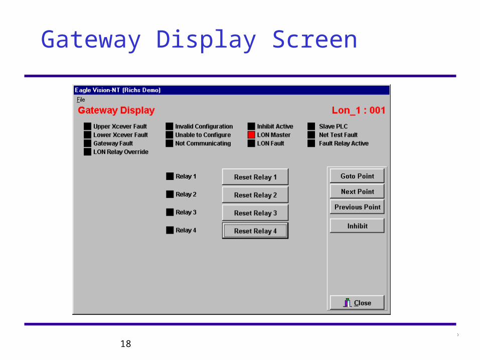
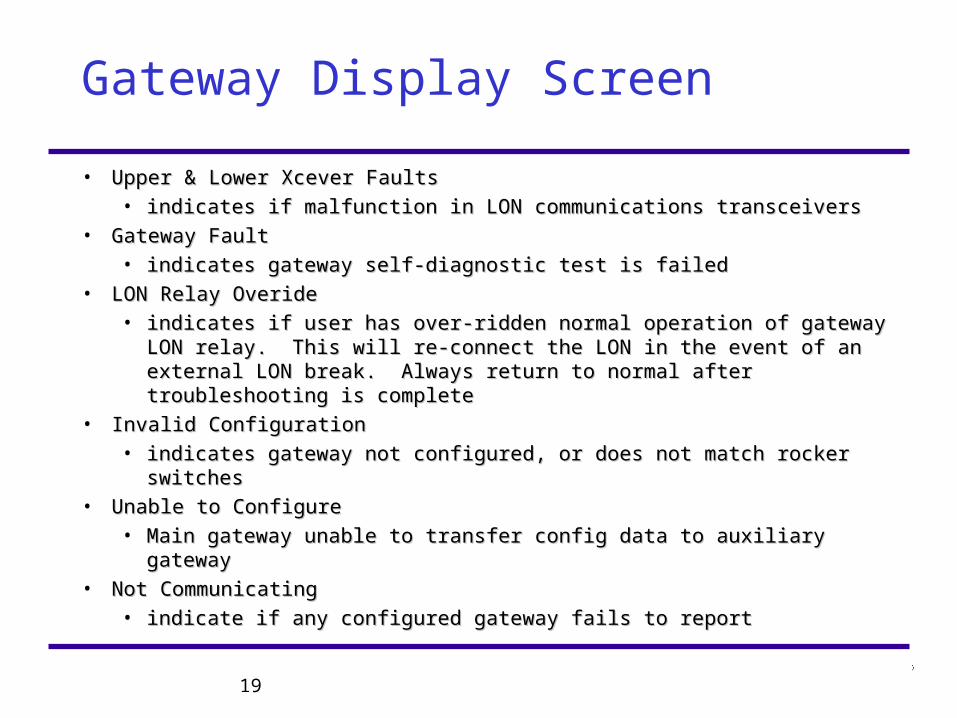
Gateway Display Screen
• Upper & Lower Xcever FaultsUpper & Lower Xcever Faults
• indicates if malfunction in LON communications transceiversindicates if malfunction in LON communications transceivers
• Gateway FaultGateway Fault
• indicates gateway self-diagnostic test is failedindicates gateway self-diagnostic test is failed
• LON Relay OverideLON Relay Overide
• indicates if user has over-ridden normal operation of gateway LON indicates if user has over-ridden normal operation of gateway LON relay. This will re-connect the LON in the event of an external LON relay. This will re-connect the LON in the event of an external LON break. Always return to normal after troubleshooting is completebreak. Always return to normal after troubleshooting is complete
• Invalid ConfigurationInvalid Configuration
• indicates gateway not configured, or does not match rocker switchesindicates gateway not configured, or does not match rocker switches
• Unable to ConfigureUnable to Configure
• Main gateway unable to transfer config data to auxiliary gatewayMain gateway unable to transfer config data to auxiliary gateway
• Not CommunicatingNot Communicating
• indicate if any configured gateway fails to reportindicate if any configured gateway fails to report
20
Gateway Display Screen
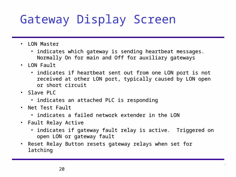
• LON MasterLON Master
• indicates which gateway is sending heartbeat messages. Normally indicates which gateway is sending heartbeat messages. Normally On for main and Off for auxiliary gatewaysOn for main and Off for auxiliary gateways
• LON FaultLON Fault
• indicates if heartbeat sent out from one LON port is not received at indicates if heartbeat sent out from one LON port is not received at other LON port, typically caused by LON open or short circuitother LON port, typically caused by LON open or short circuit
• Slave PLCSlave PLC
• indicates an attached PLC is respondingindicates an attached PLC is responding
• Net Test FaultNet Test Fault
• indicates a failed network extender in the LONindicates a failed network extender in the LON
• Fault Relay ActiveFault Relay Active
• indicates if gateway fault relay is active. Triggered on open LON or indicates if gateway fault relay is active. Triggered on open LON or gateway faultgateway fault
• Reset Relay Button resets gateway relays when set for latchingReset Relay Button resets gateway relays when set for latching
21
Point Display Screens
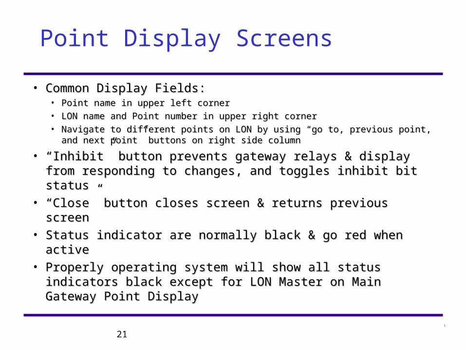
• Common Display Fields:Common Display Fields:• Point name in upper left cornerPoint name in upper left corner
• LON name and Point number in upper right cornerLON name and Point number in upper right corner
• Navigate to different points on LON by using “go to, previous point, and Navigate to different points on LON by using “go to, previous point, and next point” buttons on right side columnnext point” buttons on right side column
• ““Inhibit” button prevents gateway relays & display from Inhibit” button prevents gateway relays & display from responding to changes, and toggles inhibit bit statusresponding to changes, and toggles inhibit bit status
• ““Close” button closes screen & returns previous screenClose” button closes screen & returns previous screen• Status indicator are normally black & go red when activeStatus indicator are normally black & go red when active• Properly operating system will show all status indicators Properly operating system will show all status indicators
black except for LON Master on Main Gateway Point black except for LON Master on Main Gateway Point DisplayDisplay
22
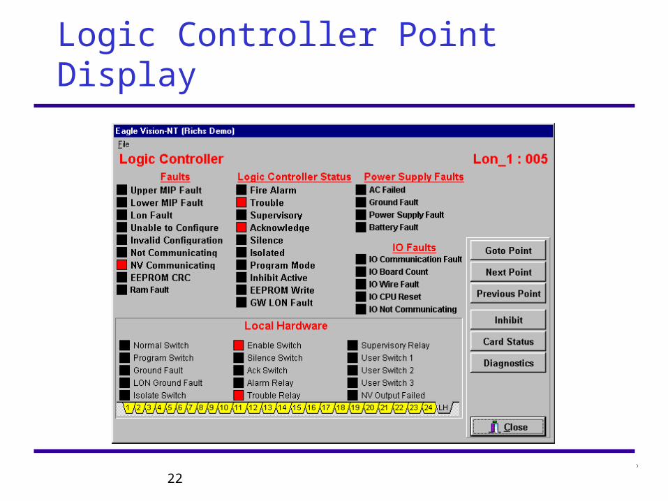
Logic Controller Point Display
23
Logic Controller Point Display
• FaultsFaults
• Upper & Lower MIP FaultsUpper & Lower MIP Faults indicate LON transceiver malfunction indicate LON transceiver malfunction
• LON faultLON fault indicates a loss of heartbeat from main gateway indicates a loss of heartbeat from main gateway
• Unable to ConfigureUnable to Configure indicates an unsuccessful transfer of indicates an unsuccessful transfer of configuration data from main gatewayconfiguration data from main gateway
• Invalid ConfigurationInvalid Configuration indicates re-configuration is required indicates re-configuration is required
• Not CommunicatingNot Communicating indicates the Logic controller has failed to indicates the Logic controller has failed to report on schedulereport on schedule
• NV CommunicatingNV Communicating indicates a field device is not reporting to Logic indicates a field device is not reporting to Logic
• EEPROM CRCEEPROM CRC indicates Logic controller needs to be replaced indicates Logic controller needs to be replaced
• RAM FaultRAM Fault indicates new configuration data has been downloaded indicates new configuration data has been downloaded but not saved to non-volatile memory. Perform “write EEPROM” but not saved to non-volatile memory. Perform “write EEPROM” function to clear this faultfunction to clear this fault
24
Logic Controller Status
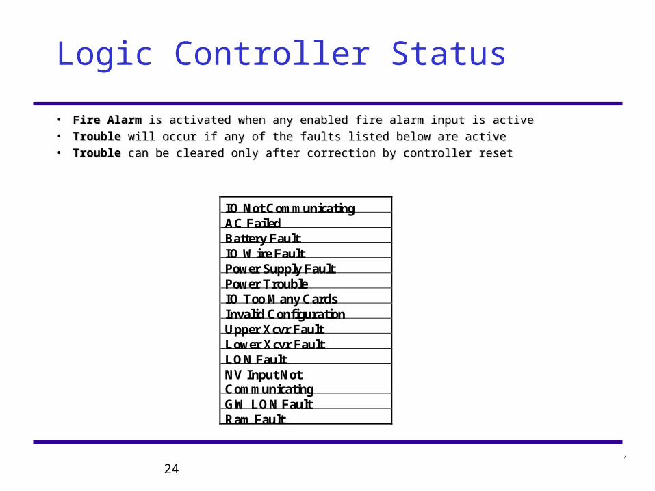
IO Not CommunicatingAC FailedBattery FaultIO Wire FaultPower Supply FaultPower TroubleIO Too Many CardsInvalid ConfigurationUpper Xcvr FaultLower Xcvr FaultLON FaultNV Input NotCommunicatingGW LON FaultRam Fault
• Fire AlarmFire Alarm is activated when any enabled fire alarm input is active is activated when any enabled fire alarm input is active• TroubleTrouble will occur if any of the faults listed below are active will occur if any of the faults listed below are active• TroubleTrouble can be cleared only after correction by controller reset can be cleared only after correction by controller reset
25
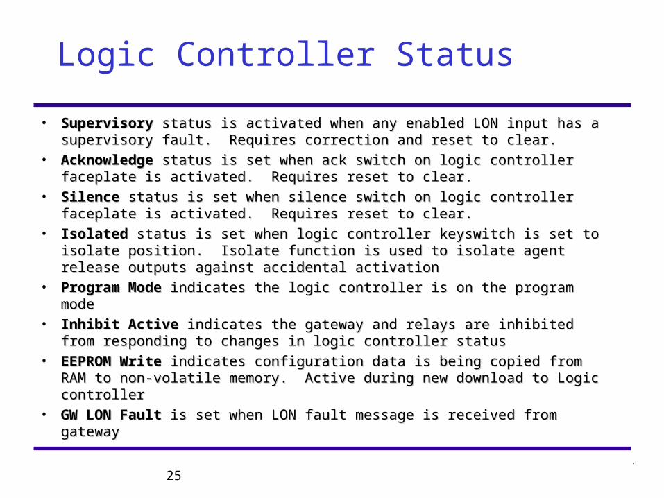
Logic Controller Status
• SupervisorySupervisory status is activated when any enabled LON input has a status is activated when any enabled LON input has a supervisory fault. Requires correction and reset to clear.supervisory fault. Requires correction and reset to clear.
• AcknowledgeAcknowledge status is set when ack switch on logic controller faceplate status is set when ack switch on logic controller faceplate is activated. Requires reset to clear.is activated. Requires reset to clear.
• Silence Silence status is set when silence switch on logic controller faceplate is status is set when silence switch on logic controller faceplate is activated. Requires reset to clear.activated. Requires reset to clear.
• IsolatedIsolated status is set when logic controller keyswitch is set to isolate status is set when logic controller keyswitch is set to isolate position. Isolate function is used to isolate agent release outputs against position. Isolate function is used to isolate agent release outputs against accidental activationaccidental activation
• Program ModeProgram Mode indicates the logic controller is on the program mode indicates the logic controller is on the program mode
• Inhibit ActiveInhibit Active indicates the gateway and relays are inhibited from indicates the gateway and relays are inhibited from responding to changes in logic controller statusresponding to changes in logic controller status
• EEPROM WriteEEPROM Write indicates configuration data is being copied from RAM to indicates configuration data is being copied from RAM to non-volatile memory. Active during new download to Logic controllernon-volatile memory. Active during new download to Logic controller
• GW LON FaultGW LON Fault is set when LON fault message is received from gateway is set when LON fault message is received from gateway
26
Logic Controller Power Supply Faults
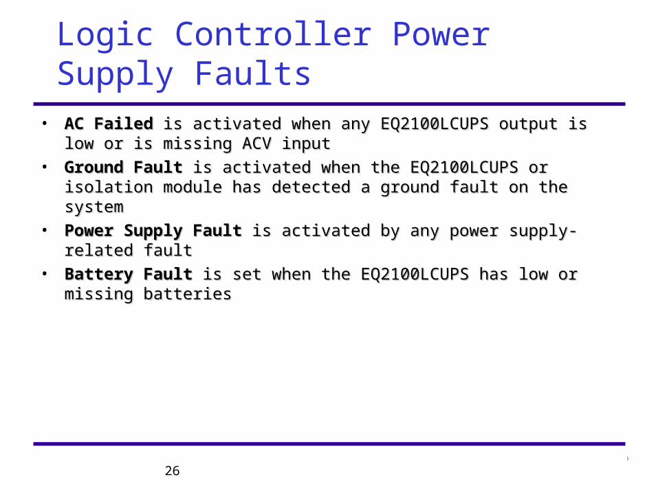
• AC FailedAC Failed is activated when any EQ2100LCUPS output is low or is missing is activated when any EQ2100LCUPS output is low or is missing ACV inputACV input
• Ground FaultGround Fault is activated when the EQ2100LCUPS or isolation module has is activated when the EQ2100LCUPS or isolation module has detected a ground fault on the systemdetected a ground fault on the system
• Power Supply FaultPower Supply Fault is activated by any power supply-related fault is activated by any power supply-related fault
• Battery FaultBattery Fault is set when the EQ2100LCUPS has low or missing batteries is set when the EQ2100LCUPS has low or missing batteries
27
Logic Controller IO Faults
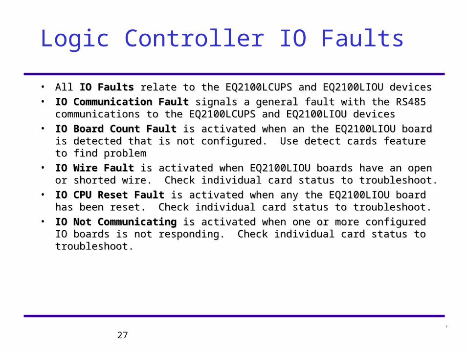
• All All IO FaultsIO Faults relate to the EQ2100LCUPS and EQ2100LIOU devices relate to the EQ2100LCUPS and EQ2100LIOU devices
• IO Communication FaultIO Communication Fault signals a general fault with the RS485 signals a general fault with the RS485 communications to the EQ2100LCUPS and EQ2100LIOU devicescommunications to the EQ2100LCUPS and EQ2100LIOU devices
• IO Board Count FaultIO Board Count Fault is activated when an the EQ2100LIOU board is is activated when an the EQ2100LIOU board is detected that is not configured. Use detect cards feature to find problemdetected that is not configured. Use detect cards feature to find problem
• IO Wire FaultIO Wire Fault is activated when EQ2100LIOU boards have an open or is activated when EQ2100LIOU boards have an open or shorted wire. Check individual card status to troubleshoot.shorted wire. Check individual card status to troubleshoot.
• IO CPU Reset FaultIO CPU Reset Fault is activated when any the EQ2100LIOU board has is activated when any the EQ2100LIOU board has been reset. Check individual card status to troubleshoot.been reset. Check individual card status to troubleshoot.
• IO Not CommunicatingIO Not Communicating is activated when one or more configured IO is activated when one or more configured IO boards is not responding. Check individual card status to troubleshoot. boards is not responding. Check individual card status to troubleshoot.
28
Logic Controller Card Status
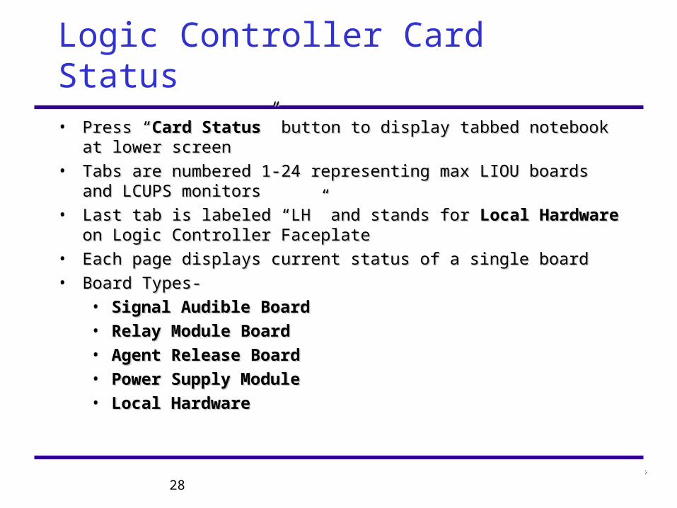
• Press “Press “Card StatusCard Status” button to display tabbed notebook at lower screen” button to display tabbed notebook at lower screen
• Tabs are numbered 1-24 representing max LIOU boards and LCUPS Tabs are numbered 1-24 representing max LIOU boards and LCUPS monitorsmonitors
• Last tab is labeled “LH” and stands for Last tab is labeled “LH” and stands for Local HardwareLocal Hardware on Logic on Logic Controller FaceplateController Faceplate
• Each page displays current status of a single boardEach page displays current status of a single board
• Board Types-Board Types-
• Signal Audible BoardSignal Audible Board
• Relay Module BoardRelay Module Board
• Agent Release BoardAgent Release Board
• Power Supply ModulePower Supply Module
• Local HardwareLocal Hardware
29
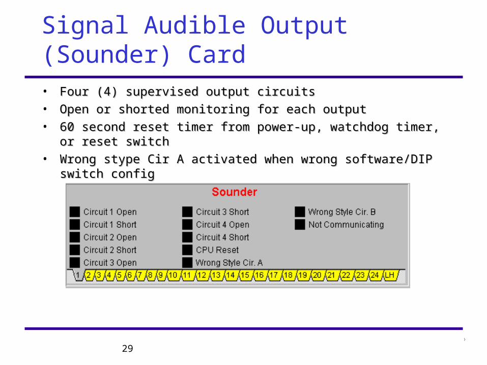
Signal Audible Output (Sounder) Card
• Four (4) supervised output circuitsFour (4) supervised output circuits
• Open or shorted monitoring for each outputOpen or shorted monitoring for each output
• 60 second reset timer from power-up, watchdog timer, or reset switch60 second reset timer from power-up, watchdog timer, or reset switch
• Wrong stype Cir A activated when wrong software/DIP switch configWrong stype Cir A activated when wrong software/DIP switch config
30
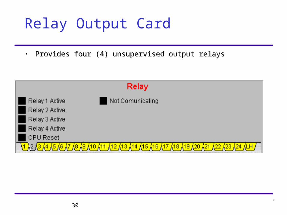
Relay Output Card
• Provides four (4) unsupervised output relaysProvides four (4) unsupervised output relays
31
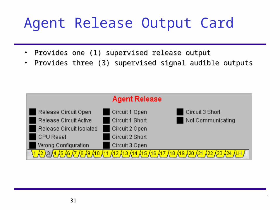
Agent Release Output Card
• Provides one (1) supervised release outputProvides one (1) supervised release output
• Provides three (3) supervised signal audible outputsProvides three (3) supervised signal audible outputs
32
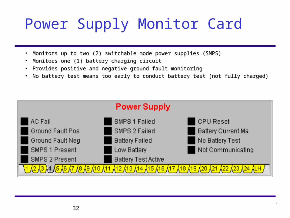
Power Supply Monitor Card
• Monitors up to two (2) switchable mode power supplies (SMPS)Monitors up to two (2) switchable mode power supplies (SMPS)• Monitors one (1) battery charging circuitMonitors one (1) battery charging circuit• Provides positive and negative ground fault monitoringProvides positive and negative ground fault monitoring• No battery test means too early to conduct battery test (not fully charged)No battery test means too early to conduct battery test (not fully charged)
33
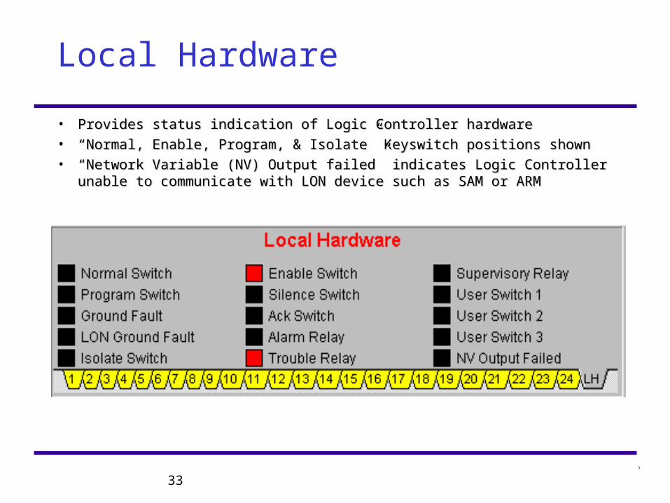
Local Hardware
• Provides status indication of Logic Controller hardwareProvides status indication of Logic Controller hardware
• ““Normal, Enable, Program, & Isolate” Keyswitch positions shownNormal, Enable, Program, & Isolate” Keyswitch positions shown
• ““Network Variable (NV) Output failed” indicates Logic Controller unable Network Variable (NV) Output failed” indicates Logic Controller unable to communicate with LON device such as SAM or ARMto communicate with LON device such as SAM or ARM
34
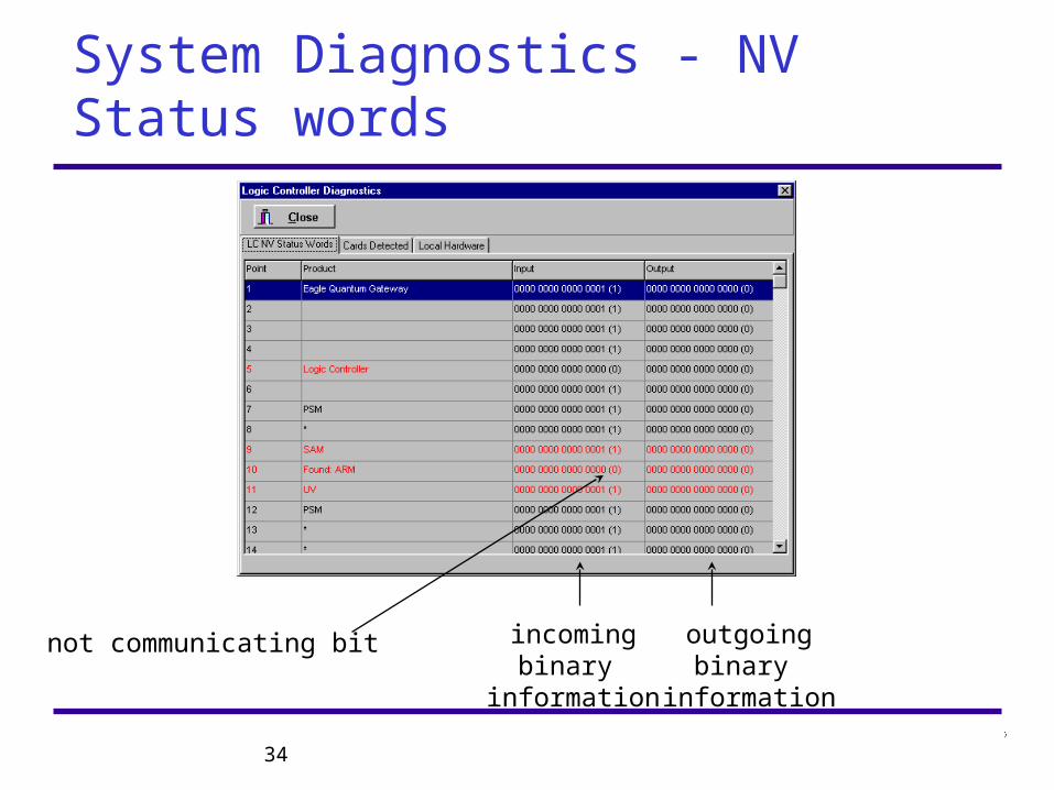
System Diagnostics - NV Status words
incomingbinary
information
outgoingbinary
information
not communicating bit
35
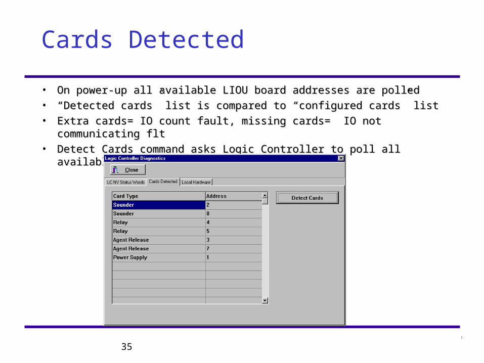
Cards Detected
• On power-up all available LIOU board addresses are polledOn power-up all available LIOU board addresses are polled
• ““Detected cards” list is compared to “configured cards” listDetected cards” list is compared to “configured cards” list
• Extra cards= IO count fault, missing cards= IO not communicating fltExtra cards= IO count fault, missing cards= IO not communicating flt
• Detect Cards command asks Logic Controller to poll all available cardsDetect Cards command asks Logic Controller to poll all available cards
36
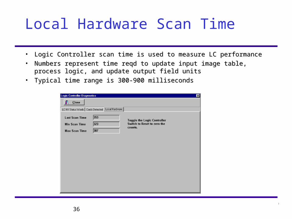
Local Hardware Scan Time
• Logic Controller scan time is used to measure LC performanceLogic Controller scan time is used to measure LC performance
• Numbers represent time reqd to update input image table, process Numbers represent time reqd to update input image table, process logic, and update output field unitslogic, and update output field units
• Typical time range is 300-900 millisecondsTypical time range is 300-900 milliseconds
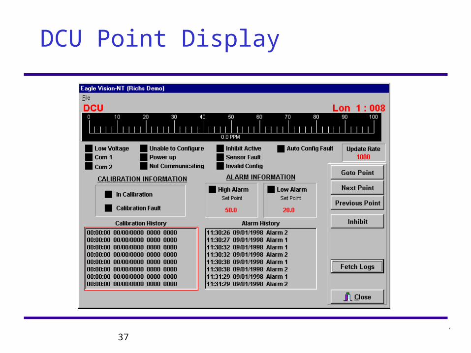
37
DCU Point Display
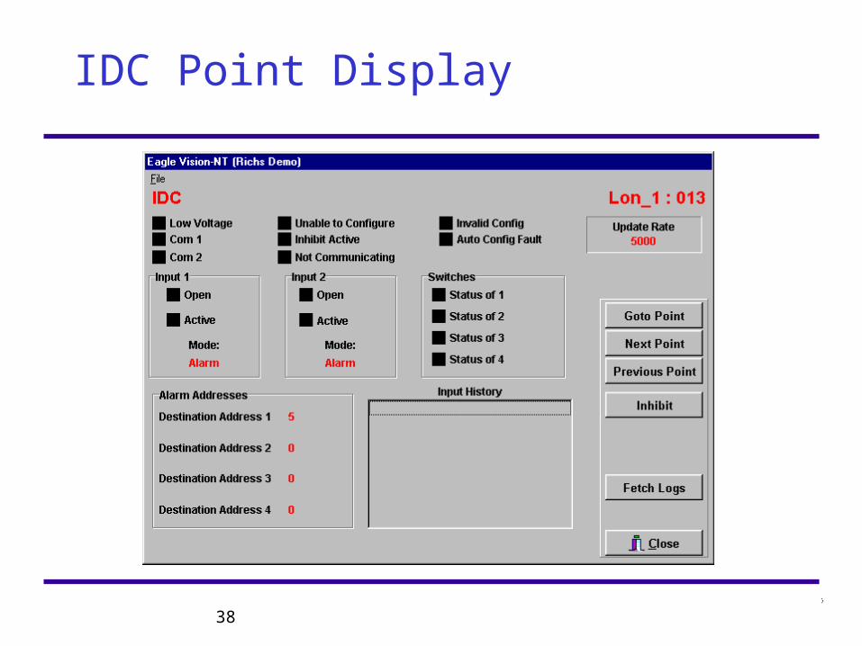
38
IDC Point Display
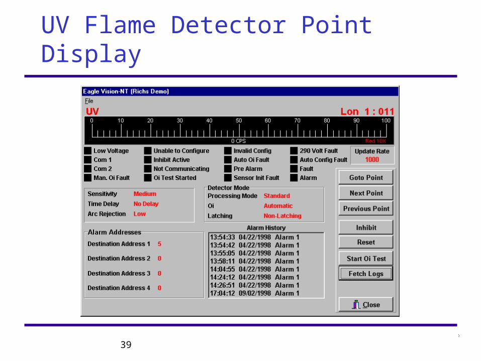
39
UV Flame Detector Point Display
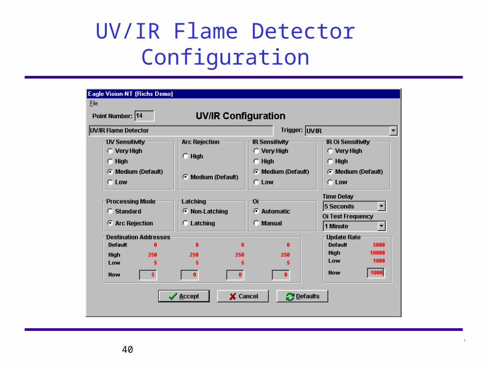
40
UV/IR Flame Detector Configuration
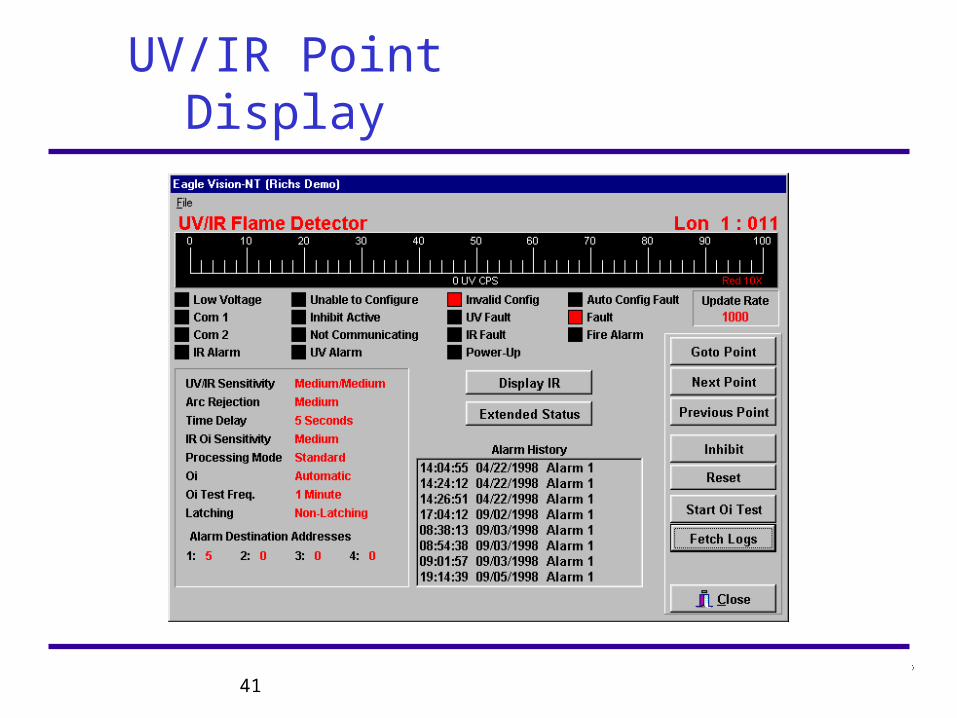
41
UV/IR Point Display
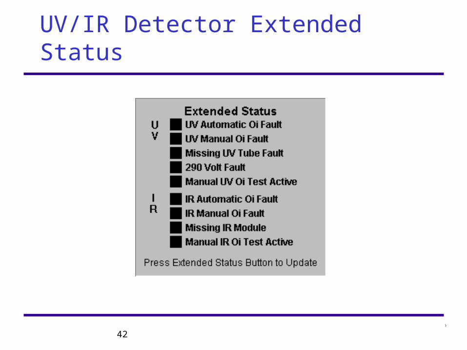
42
UV/IR Detector Extended Status
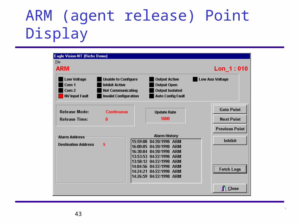
43
ARM (agent release) Point Display
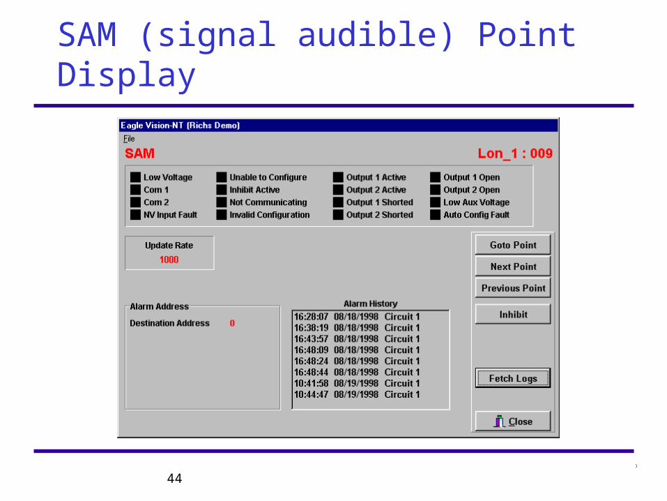
44
SAM (signal audible) Point Display
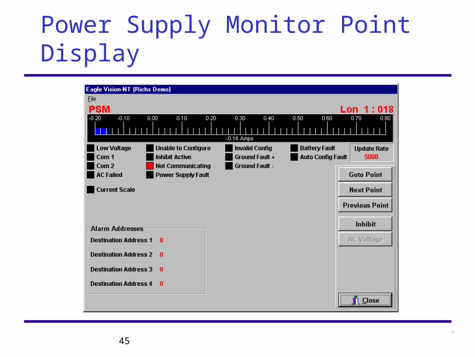
45
Power Supply Monitor Point Display
46
Quantum LON Troubleshooting
• Typical Quantum Trouble-Typical Quantum Trouble-• LON Wiring Fault (check Overview screen)LON Wiring Fault (check Overview screen)• Node Address ErrorNode Address Error• Extra, Missing, or unconfigured LIOU CardsExtra, Missing, or unconfigured LIOU Cards
47
Quantum LON Troubleshooting
• System Overview screen showsSystem Overview screen shows• Configured nodes displayed as block w/addressConfigured nodes displayed as block w/address• Node color codes: Black= normal, Red= alarm, Node color codes: Black= normal, Red= alarm,
Yellow= faultYellow= fault• Select LON Diag. ButtonSelect LON Diag. Button
• LON Diagnostic screen displayedLON Diagnostic screen displayed• Node color changes indicate communicationsNode color changes indicate communications• Green= LON1, Blue= LON2, Red= No comm.Green= LON1, Blue= LON2, Red= No comm.
48
Quantum Printing Function
• Print Functions for-Print Functions for-• Field Device Configuration by Point #Field Device Configuration by Point #• Trigger names, types, and eventsTrigger names, types, and events• Logic pages and gate assignmentsLogic pages and gate assignments• Event LogEvent Log
49
Quantum Printing Function
• Quantum Print function tested at FactoryQuantum Print function tested at Factory• Cable length limits exist!Cable length limits exist!• Printer compatibility limits exist!Printer compatibility limits exist!• Unauthorized changes may impact Printing Unauthorized changes may impact Printing
capabilitiescapabilities