1 robust layered transmission in secure miso multiuser...
TRANSCRIPT

arX
iv:s
ubm
it/10
0829
7 [c
s.IT
] 25
Jun
201
41
Robust Layered Transmission in Secure MISO
Multiuser Unicast Cognitive Radio Systems
Derrick Wing Kwan Ng∗, Mohammad Shaqfeh‡, Robert Schober†, and Hussein Alnuweiri§
Institute for Digital Communications, Friedrich-Alexander-University Erlangen-Nurnberg
(FAU), Germany∗†
Texas A&M University at Qatar, Qatar‡§
Email: [email protected], [email protected], [email protected],
Abstract
This paper studies robust resource allocation algorithm design for a multiuser multiple-input single-output
(MISO) cognitive radio (CR) downlink communication network. We focus on a secondary system which provides
unicast secure wireless layered video information to multiple single-antenna secondary receivers. The resource
allocation algorithm design is formulated as a non-convex optimization problem for minimization of the total
transmit power at the secondary transmitter. The proposed framework takes into account a quality of service (QoS)
requirement regarding video communication secrecy in the secondary system, the imperfection of the channel
state information (CSI) of potential eavesdroppers (primary receivers) at the secondary transmitter, and a limit
for the maximum tolerable received interference power at the primary receivers. Thereby, the proposed problem
formulation exploits theself-protectingarchitecture of layered transmission and artificial noise generation to ensure
communication secrecy. Semidefinite programming (SDP) relaxation is employed to derive a resource allocation
algorithm which finds the global optimal solution to the formulated problem. Simulation results demonstrate
significant transmit power savings and robustness against CSI imperfection for the proposed resource allocation
algorithm for layered transmission compared to baseline schemes with traditional single-layer transmission.
Index Terms
Layered transmission, physical layer security, cognitiveradio, non-convex optimization.
∗†The authors are also with the University of British Columbia, Vancouver, Canada. This paper has been presented in part atthe IEEE
WCNC 2014 [1]. This research was supported by the Qatar National Research Fund (QNRF), under project NPRP 5-401-2-161.
Wednesday 25th June, 2014 DRAFT

2
I. INTRODUCTION
In recent years, the rapid expansion of high data rate multimedia services in wireless communication
networks has led to a tremendous demand for energy and bandwidth. Consequently, multiple-input multiple-
output (MIMO) technology has emerged as one of the most prominent solutions in reducing the system
power consumption. In particular, MIMO provides extra spatial degrees of freedom for resource allocation
[1]–[6] which facilitates a trade-off between multiplexing and diversity. Unfortunately, the hardware
complexity of multiple-antenna receivers constrains the deployment of MIMO in practice, especially for
small portable mobile devices. As an alternative, multiuser MIMO has been proposed as a compromise
solution for realizing the potential performance gain offered by multiple antennas. Specifically, multiuser
MIMO allows a multiple-antenna transmitter to serve multiple single-antenna receivers; it shifts the signal
processing burden from the receivers to the transmitter while providing a promising system performance.
On the other hand, fixed spectrum assignment has been implemented for resource sharing in traditional
wireless communication systems. Although this design facilitates a simple implementation and interference
can be avoided by assigning different wireless services to orthogonal licensed frequency bands, the fixed
spectrum allocation strategy may result in spectrum underutilization and scarcity. In practice, the demand
for spectrum varies highly across time, frequency, and space. For instance, the Federal Communications
Commission (FCC) has reported that70 percent of the allocated spectrum in the United States is not
fully utilized, cf. [7]. As a result, cognitive radio (CR) was proposed as a possible solution for improving
spectrum utilization [8]. CR enables a secondary system to dynamically access the spectrum of a primary
system if the interference from the secondary system is controlled such that it does not severely degrade
the quality of service (QoS) of the primary system [7]–[17].Spectrum sensing plays an important role for
facilitating the spectrum reuse in CR networks and has received considerable interest in the literature. In [9]
and [10], cooperative spectrum sensing was investigated for two-user and multiuser single-antenna systems,
respectively. In [11], the authors optimized the spectrum sensing duration for throughput maximization
in the secondary network while protecting the primary users. In [12], an optimal linear cooperation
framework was proposed to detect weak signals from primary users by combining the local statistics of
individual CRs. Furthermore, different resource allocation algorithms have been studied for controlling the
interference leakage from the secondary network to the primary network. By exploiting multiple antennas in
a secondary transmitter, beamforming designs minimizing the transmit power of a CR secondary downlink
system were studied in [13]. In [14], joint beamforming and power control for multiple access channels
was studied by assuming the availability of perfect channelstate information (CSI). Later, in [15] and [16],
the beamforming algorithm design was improved by taking into account the imperfection of the CSI in
practical single and multiple secondary users systems, respectively. In [17], multiple objective optimization
Wednesday 25th June, 2014 DRAFT

3
adopted for CR networks to study the trade-off between the interference leakage to the primary network
and the transmit power of the secondary transmitter. However, the problem formulations in [13]–[17] did
not take into account the characteristics of the underlyingcommunication services. Besides, the results in
[13]–[17] were obtained by assuming single-antenna primary receivers. Thus, the corresponding results
may not be applicable to CR networks with multiple antenna primary receivers and secondary networks
providing multimedia applications such as video streaming.
Scalable video coding (SVC) [18], [19] has been proposed forvideo information encoding. In particular,
multiple description coding (MDC) and successive refinement coding (SRC) are two common multimedia
SVC techniques. For MDC, the video source signal is encoded into multiple sub-streams(/descriptions),
each of which has equal importance. Besides, each description can be decoded independently without uti-
lizing the information embedded in other descriptions. Also, each decoded description alone can guarantee
a basic level of video quality and combining additional descriptions can further improve the quality. On the
other hand, in SRC, a video signal is encoded into a hierarchyof multiple layers with unequal importance,
namely one base layer and several enhancement layers. The base layer contains the essential information
of the video with minimum video quality. The information embedded in each enhancement layer is used to
successively refine the description of the pervious layers.The structure of layered transmission facilitates
the implementation of unequal error protection. In fact, SRC provides a higher flexility to the service
provider compared to MDC since the transmitter can achieve abetter resource utilization by allocating
different powers to different information layers depending on the required video quality. Besides, layered
transmission with SRC has been implemented in some existingvideo standards such as H.264/Moving
Picture Experts Group (MPEG)-4. Thus, in this paper, we focus on layered transmission based on SRC.
Recently, resource allocation algorithm design for layered transmission has been pursued for wireless
communication systems. In [20], power allocation in layered transmission with successive enhancement
was investigated. Subsequently, this study was extended tothe joint design of rate and power allocation in
[21]. Yet, the resource allocation algorithms in [20] and [21] are designed for single antenna transmitters
with long-term average system design objectives. Hence, the results of [20] and [21] may not be applicable
for delay-sensitive application and multiple antennas systems.
Furthermore, wireless communication channels are vulnerable to eavesdropping due to their broadcast
nature. As soliciting multimedia services over the wireless medium becomes more popular, there is an
emerging need for guaranteeing secure wireless video communication. For instance, illegitimate users or
misbehaving legitimate users of a communication system mayattempt to use high definition video services
without paying by overhearing the video signal. Conventionally, secure communication is guaranteed by
cryptographic encryption algorithms implemented in the application layer. However, the associated required
Wednesday 25th June, 2014 DRAFT
4
secrete key distribution and management can be problematicor infeasible in wireless networks. Besides,
with the development of quantum computing, the commonly used encryption algorithms may become
eventually crackable with brute force approach within a reasonable amount of time. As a result, physical
(PHY) layer security [22]–[28] has been proposed as a complement to the traditional secrecy methods for
improving wireless transmission security. The merit of PHYlayer security lies in the guaranteed perfect
secrecy of communication, even if the eavesdroppers have unbounded computational capability. In [22],
Wyner showed that a non-zero secrecy capacity, defined as themaximum transmission rate at which an
eavesdropper is unable to extract any information from the received signal, can be achieved if the desired
receiver enjoys better channel conditions than the eavesdropper. This result was subsequently generalized
to the broadcast channel and the Gaussian channel in [23] and[24], respectively. Recently, a considerable
amount of research [25]–[28] has been devoted to exploitingmultiple antennas for providing communi-
cation secrecy. In [25], a suboptimal transmit beamformingscheme was proposed for maximization of
the minimum secrecy capacity in a multiple-input single-output (MISO) multicast communication system.
In [26] and [27], artificial noise generation was exploited for multiple-antenna transmitters to weaken
the information interception capabilities of the eavesdroppers. In particular, artificial noise is transmitted
concurrently with the information signal in [26] and [27] for maximization of the ergodic secrecy capacity
and the outage secrecy capacity, respectively. In [28], a joint power and subcarrier allocation algorithm
was proposed for maximization of the system energy efficiency of wide-band communication systems
while providing communication secrecy. However, single-layer transmission is assumed in [25]–[28] and
the corresponding results may not be applicable to the layered transmission structure used in multimedia
applications. In fact, the layered information architecture of video signals has aself-protecting structure
which provides a certain robustness against eavesdropping. However, exploiting the layered transmission
architecture for facilitating PHY layer security for videocommunication has not been considered in the
literature, e.g., [4]–[21]. The notion of secure communication in layered transmission systems has recently
been studied in our preliminary work in [1]. Specifically, a power allocation algorithm was designed for
minimization of the transmit power under a communication secrecy constraint for a single video receiver.
Yet, with the design proposed in [1], a strong artificial noise/interference is generated to ensure secure
video communication and this may cause a significant performance degradation for the primary receivers
if the results of [1] are directly applied to CR networks.
In this paper, we address the above issues and the contributions of the paper are summarized as follows:
• We propose a non-convex optimization problem formulation for minimization of the total transmit
power in layered video transmission to multiple secondary receivers. The proposed framework takes
into account the imperfection of the CSI of the potential eavesdroppers (primary receivers) for
Wednesday 25th June, 2014 DRAFT

5
guaranteeing secure communication to the secondary receivers and controlling the interference leakage
to the multiple-antenna primary receivers.
• The considered non-convex optimization problem is recast as a convex optimization problem via
semidefinite programming (SDP) relaxation. We prove that the global optimal solution of the original
problem can be constructed by exploiting the solutions of the primal and the dual versions of the
SDP relaxed problem.
• Two suboptimal resource allocation schemes are proposed for the case when the solution of the dual
problem of the SDP relaxed problem is unavailable for construction of the optimal solution.
• Our simulation results show that the inherentlyself-protectingstructure of layered transmission
enables significant transmit power savings in providing secure video communication for the secondary
receivers compared to two baseline schemes employing traditional single-layer transmission.
II. SYSTEM MODEL
In this section, we present the adopted system model for secure layered video transmission.
A. Notation
We use boldface capital and lower case letters to denote matrices and vectors, respectively.AH , Tr(A),
A12 , Rank(A), anddet(A) represent the Hermitian transpose, trace, square-root, rank, and determinant
of matrix A; vec(A) denotes the vectorization of matrixA by stacking its columns from left to right
to form a column vector;A ⊗ B denotes the Kronecker product of matricesA and B; A ≻ 0 and
A 0 indicate thatA is a positive definite and a positive semidefinite matrix, respectively; λmax(A)
denotes the maximum eigenvalue of matrixA; IN is theN × N identity matrix;CN×M denotes the set
of all N ×M matrices with complex entries;HN denotes the set of allN ×N Hermitian matrices. The
circularly symmetric complex Gaussian (CSCG) distribution is denoted byCN (m,Σ) with mean vector
m and covariance matrixΣ; ∼ indicates “distributed as”;|·|, ‖·‖, and‖·‖F denote the absolute value of
a complex scalar, the Euclidean norm, and the Frobenius normof a vector/matrix, respectively.
B. Channel Model
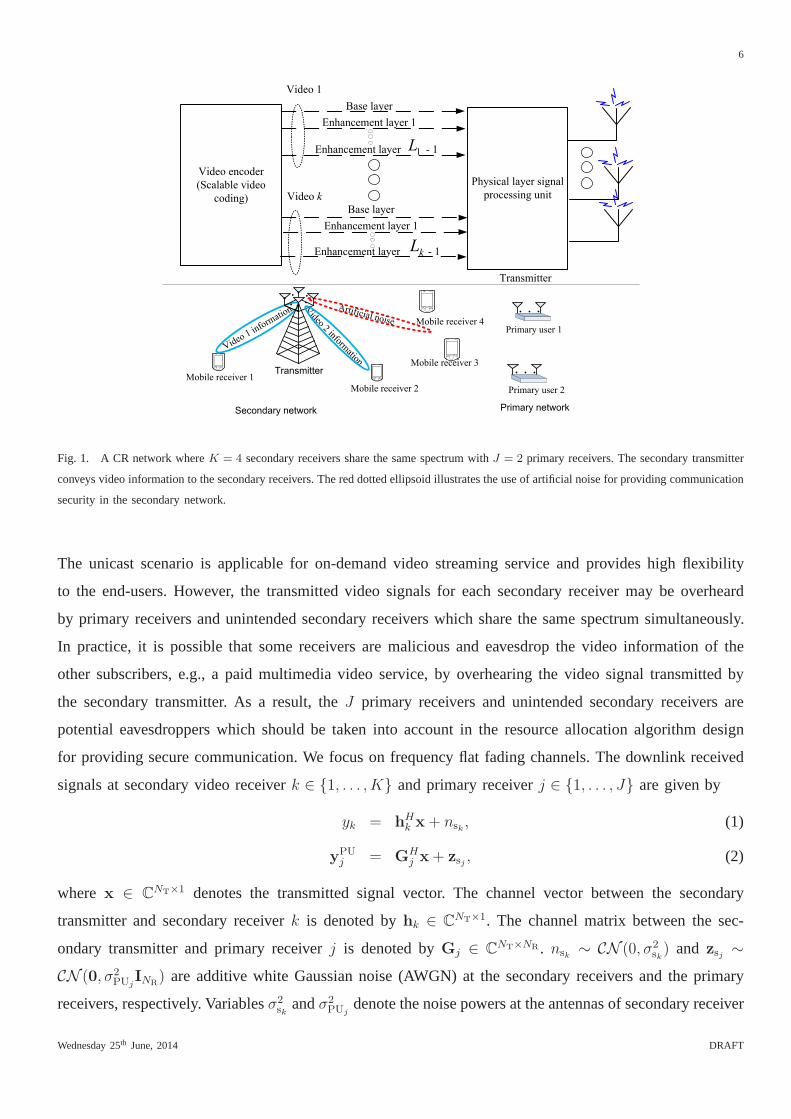
We consider a CR secondary network. There are one secondary transmitter equipped withNT > 1 trans-
mit antennas,K legitimate secondary video receivers, andJ primary receivers. The secondary receivers
and the primary receivers share the same spectrum concurrently, cf. Figure 1. The secondary receivers are
low complexity single-antenna devices for decoding the video signal. On the other hand, each primary
receiver is equipped withNR > 1 antennas. We assume thatNT > NR in this paper. In every time
instant, the transmitter conveysK video information signals toK unicast secondary video receivers.
Wednesday 25th June, 2014 DRAFT
6
Transmitter
Mobile receiver 4
Mobile receiver 1
Video 1 inform
ation
Transmitter
Artificial noise
Mobile receiver 2
Secondary network Primary network
Video 2 inform
ation Mobile receiver 3
Primary user 1
Primary user 2
Video encoder
(Scalable video
coding)
Physical layer signal
processing unit
Base layer
Enhancement layer 1
Video 1
Video k
Base layer
Enhancement layer 1
Enhancement layer - 1
Enhancement layer - 1
kL
1L
Fig. 1. A CR network whereK = 4 secondary receivers share the same spectrum withJ = 2 primary receivers. The secondary transmitter
conveys video information to the secondary receivers. The red dotted ellipsoid illustrates the use of artificial noise for providing communication
security in the secondary network.
The unicast scenario is applicable for on-demand video streaming service and provides high flexibility
to the end-users. However, the transmitted video signals for each secondary receiver may be overheard
by primary receivers and unintended secondary receivers which share the same spectrum simultaneously.
In practice, it is possible that some receivers are malicious and eavesdrop the video information of the
other subscribers, e.g., a paid multimedia video service, by overhearing the video signal transmitted by
the secondary transmitter. As a result, theJ primary receivers and unintended secondary receivers are
potential eavesdroppers which should be taken into accountin the resource allocation algorithm design
for providing secure communication. We focus on frequency flat fading channels. The downlink received
signals at secondary video receiverk ∈ 1, . . . , K and primary receiverj ∈ 1, . . . , J are given by
yk = hHk x + nsk , (1)
yPUj = GH
j x+ zsj , (2)
where x ∈ CNT×1 denotes the transmitted signal vector. The channel vector between the secondary
transmitter and secondary receiverk is denoted byhk ∈ CNT×1. The channel matrix between the sec-
ondary transmitter and primary receiverj is denoted byGj ∈ CNT×NR . nsk ∼ CN (0, σ2
sk) and zsj ∼
CN (0, σ2PUj
INR) are additive white Gaussian noise (AWGN) at the secondary receivers and the primary
receivers, respectively. Variablesσ2sk
andσ2PUj
denote the noise powers at the antennas of secondary receiver
Wednesday 25th June, 2014 DRAFT

7
k and primary receiverj, respectively. We assume that the primary network is a legacy system which does
not participate in adaptive transmit power control. The received power from the primary transmitter at the
secondary receivers is incorporated in the AWGN,nsk .
C. Video Encoding and Artificial Noise
Layered video encoding based on SRC is adopted to encode the video information. Specifically, the
video source intended for secondary receiverk is encoded intoLk layers at the secondary transmitter
and the data rate of each layer is fixed, cf. H.264/SVC [18], [19]. The video information for secondary
receiverk can be represented asSk =[s1,k, s2,k, . . . , sl,k . . . , sLk,k
], wheresl,k ∈ C denotes the video
information of layerl for secondary receiverk. For the video signal of receiverk, theLk layers include
one base layer, i.e.,s1,k, which can be decoded independently without utilizing the information from the
upper layers. Specifically, the base layer data includes themost essential information of the video and
can guarantee a basic video quality. The remainingLk − 1 layers, i.e.,s2,k, . . . , sLk,k, are enhancement
layers which are used to successively refine the decoded lower layers. In other words, the enhancement
layers cannot be decoded independently; if the decoding of alayer fails, the information embedded in the
following enhancement layers is lost since they are no longer decodable.
Furthermore, in order to provide communication security, artificial noise is transmitted along with the
information signals. Hence, the transmit symbol vectorx can be expressed as
x =K∑
k=1
Lk∑
l=1
wl,ksl,k
︸ ︷︷ ︸layered video signals
+ v︸︷︷︸artifical noise
, (3)
wherewl,k ∈ CNT×1 is the beamforming vector for the video information in layerl dedicated to desired
receiverk. We note that superposition coding is used to superimpose the Lk video information layers.
v ∈ CNT×1 is an artificial noise vector generated to facilitate securecommunication. In particular,v is
modeled as a complex Gaussian random vector, i.e.,v ∼ CN (0,V), whereV denotes the covariance
matrix of the artificial noise. Hence,V is a positive semidefinite Hermitian matrix, i.e.,V ∈ HNT ,V 0.
III. RESOURCEALLOCATION ALGORITHM DESIGN
In this section, we present the adopted performance metricsand the problem formulation.
A. Achievable Rate
We assume that perfect local CSI is available at the secondary video receivers. Besides, successive
interference cancellation (SIC) [2] is performed at the receivers for decoding video information. Thereby,
before decoding the information in layerl, the receivers first decode and cancel the video informationin
Wednesday 25th June, 2014 DRAFT

8
layers1, . . . , l−1 successively. Therefore, the instantaneous achievable rate between the transmitter and
primary video receiverk in layer l ∈ 1, . . . , Lk is given by
Cl,k = log2
(1 + Γl,k
)and (4)
Γl,k =|hH
k wl,k|2
K∑
n 6=k
Ln∑
r=1
|hHk wr,n|
2
︸ ︷︷ ︸multiuser interference
+
Lk∑
t=l+1
|hHk wt,k|
2
︸ ︷︷ ︸multilayer interference
+Tr(hHk Vhk) + σ2
sk
, (5)
where Γl,k is the received signal-to-interference-plus-noise ratio(SINR) of layer l at secondary video
receiverk.
On the other hand, it is possible that secondary video receiver t attempts to decode the video information
intended for secondary receiverk after decoding its own video information. Hence, secondaryvideo
receivert is also treated as a potential eavesdropper with respect to the video information of secondary
video receiverk. The instantaneous achievable rate between the transmitter of secondary receiverk and
secondary receivert in decoding layerl ∈ 1, . . . , Lk is given by
Ctl,k = log2
(1 + Γt
l,k
)and (6)
Γtl,k =
|hHt wl,k|2
K∑n 6=k
n 6=t
Ln∑r=1
|hHt wr,n|2 +
Lk∑m=l+1
|hHt wm,k|2 + Tr(hH
t Vht) + σ2st
. (7)
It can be observed from (6) that layered transmission has aself-protecting structure. Specifically, via the
first term in the denominator of (7), the higher layer information has the same effect as the artificial noise
signal v in protecting the important information encoded in the lower layers of the video signal. It is
expected that by carefully optimizing the beamforming vectors of the higher information layers, a certain
level of communication security can be achieved in the lowerlayers.
Besides, the transmitted video signals are also overheard by the primary receivers due to the broadcast
nature of the wireless communication channel. Therefore, the achievable rate between the transmitter and
primary receiverj for decoding thel-th layer signal of secondary receiverk can be represented as
CPUj
l,k = log2 det(INR
+Λ−1j,kG
Hj wl,kw
Hl,kGj
)where (8)
Λj,k = Σj +K∑
n 6=k
Ln∑
r=1
GHj wr,nw
Hr,nGj
︸ ︷︷ ︸multiuser interference
+
Lk∑
m=l+1
GHj wm,kw
Hm,kGj
︸ ︷︷ ︸multilayer interference
(9)
Σj = GHj VGj + σ2
PUjINR
≻ 0 . (10)
Wednesday 25th June, 2014 DRAFT

9
For ensuring communication security, the primary receivers are also treated as potential eavesdroppers who
attempt to decode the messages transmitted for allK desired secondary receivers. Thereby, we focus on
a worst case scenario1 for the decoding capability of the primary receivers for providing communication
security to the secondary receivers. In particular, we assume that primary receiverj performs SIC to
remove all multiuser interference and the multilayer interference from upper layers before decoding the
message of layerl of secondary receiverk. As a result, the achievable rate in (8) is bounded above by
CPUj
l,k = log2 det(INR
+Σ−1j GH
j wl,kwHl,kGj
). (11)
Thus, the secrecy rate [26] between the transmitter and secondary receiverk on layerl is given by
Csecl,k =[Cl,k −max
∀t 6=k
∀j
Ctl,k, C
PUj
l,k ]+. (12)
Csecl,k quantifies the maximum achievable data rate at which a transmitter can reliably send secret infor-
mation on layerl to primary receiverk such that the potential eavesdroppers are unable to decode the
received signal [22].
Remark 1:We note that if secondary receivert has the same capability in eavesdropping the information
as the primary receiver, i.e., it is able to cancel the multiuser interference and multilayer interference before
eavesdropping the information of layerl of receiverk, we can use equation (11) instead of equation (8)
to denote the achievable rate between the transmitter and secondary receivert in decoding layerl of
secondary receiverk without loss of generality.
B. Channel State Information
In this paper, we focus on a Time Division Duplex (TDD) communication system with slowly time-
varying channels. At the beginning of each time slot, handshaking is performed between the secondary
transmitter and the secondary receivers. As a result, the downlink CSI of the secondary transmitter to
the secondary receivers can be obtained by measuring the uplink training sequences embedded in the
handshaking signals. Thus, we assume that the secondary-transmitter-to-secondary-receivers fading gains,
hk, can be reliably estimated at the secondary transmitter with negligible estimation error.
On the other hand, the primary receivers may not directly interact with the secondary transmitter. Besides,
the primary receivers may be silent for a long period of time due to bursty data communication. As a result,
the CSI of the primary receivers can be obtained only occasionally at the secondary transmitter when the
primary receivers communicate with the primary transmitter. Hence, the CSI for the idle primary receivers
1Although the worst case secrecy rate is assumed, the resultsof this work are also applicable to the case of primary receivers (potential
eavesdroppers) employing single user detectors by modifying the termΣj,k in (11) accordingly.
Wednesday 25th June, 2014 DRAFT

10
may be outdated when the secondary transmitter performs resource allocation. We adopt a deterministic
model [29]–[32] to model the impact of the CSI imperfection on resource allocation design. The CSI of
the link between the secondary transmitter and primary receiver j is modeled as
Gj = Gj +∆Gj , ∀j ∈ 1, . . . , J, and (13)
Ψj ,
∆Gj ∈ C
NR×NT : ‖∆Gj‖2F ≤ ε2j
, ∀j, (14)
where Gj ∈ CNR×NT is the matrix CSI estimate of the channel of primary receiverj that is available
at the secondary transmitter.∆Gj represents the unknown channel uncertainty due to the time varying
nature of the channel during transmission. In particular, the continuous setΨj in (14) defines a continuous
space spanned by all possible channel uncertainties andεj represents the maximum value of the norm of
the CSI estimation error matrix∆Gj for primary receiverj.
C. Optimization Problem Formulation
The system design objective is to minimize the total transmit power of the secondary transmitter while
providing QoS for both the secondary receivers and the primary receivers. The optimal resource allocation
policy w∗l,k,V
∗ can be obtained by solving
minimizeV∈HNT ,wl,k
K∑
k=1
Lk∑
l=1
‖wl,k‖2 + Tr(V) (15)
s.t. C1:|hH
k wl,k|2
K∑n 6=k
Ln∑r=1
|hHk wr,n|2 +
Lk∑t=l+1
|hHk wt,k|2 + Tr(hH
k Vhk) + σ2sk
≥ Γreql,k , ∀l, ∀k,
C2:|hH
t w1,k|2
K∑n 6=k
n 6=t
Ln∑l=1
|hHt wl,n|2 +
Lk∑m=2
|hHt wm,t|2 + Tr(hH
k Vhk) + σ2sk
≤ Γtol, ∀t 6= k, t ∈ 1, . . . , K,
C3: max‖∆Gj‖F∈Ψj
Tr(GH
j (V +
K∑
k=1
Lk∑
l=1
wl,kwHl,k)Gj
)≤ PIj , ∀j ∈ 1, . . . , J,
C4: max‖∆Gj‖F∈Ψj
log2 det(INR
+Σ−1j GH
j w1,kwH1,kGj
)≤ REavj,k , ∀j ∈ 1, . . . , J, ∀k ∈ 1, . . . , K,
C5: V 0.
Here, Γreql,k in C1 is the minimum required SINR for decoding layerl at receiverk. In practice, the
desired video receivers may be divided into different classes with different numbers of video layers and
different QoS requirements. For instance, the secondary video receivers may be categorized into two
categories, namelypremium video receiversandregular video receivers, based on the subscribed services.
Specifically, the secondary transmitter is required to guarantee the QoS (i.e., SINR) of all video layers
Wednesday 25th June, 2014 DRAFT

11
for premium secondary receivers while the transmitter may guarantee only the basic QoS of videos (i.e.,
the SINR of the first layer) for regular receivers. In C2,Γtol denotes the maximum tolerated received
SINR of layer1 at the unintended secondary receivers for decoding layer1 of a video signal intended
for another receiver. Since layered coding is employed for video information encoding, it is sufficient
to protect the first layer of each video signal for each secondary receiver against eavesdropping. C3 is
the interference temperature constraint. Specifically, the secondary transmitter is required to control the
transmit power such that the maximum received interferencepower at primary receiverj is less than
a given interference temperaturePIj , despite the imperfection of the CSI. We note that the considered
problem formulation is a generalization of the cases where the primary receivers are co-existing with
the secondary receivers. If the interference from the secondary transmitter to the primary receivers is not
a performance concern, we can either setPIj → ∞ or remove constraint C3 from the above problem
formulation without loss of generality. On the other hand, since any secondary receiver could be chosen
as an eavesdropping target of primary receiverj and layer transmission is adopted, the upper limitREavj,k
is imposed in C4 to restrict the achievable rate of primary receiverj, if it attempts to decode the first video
layer of secondary receiverk, ∀k. In this paper, we do not maximize the secrecy rate of video delivery as
it does not necessarily lead to a power efficient resource allocation. Yet, the problem formulation in (15)
guarantees a minimum secrecy rate of layer1 for a video signal intended for secondary receiverk, i.e.,
Csec1,k ≥[C1,k −max
∀t 6=k
∀j
log2(1+Γtol), REavj,k]+
. Besides, the communication security of layer2 to layer
Lk is ensured when layer1 in unable to be decoded by the potential eavesdroppers. C5 and V ∈ HNT are
imposed such thatV satisfies the requirements for a covariance matrix.
Remark 2:We would like to emphasize that the layered transmission approach has two major advantages
compared to single-layer transmission. First, the video quality increases with the number of decoded layers.
Thus, for layered transmission, the desired users can be easily divided into different classes with different
receive video quality for layered-transmission. In practice, the desired users may be charged with higher
subscription fees for a higher video quality. Second, the layered structure facilitates more power efficient
resource allocation under physical layer security constraints. In particular, instead of protecting the entire
encoded video signal as in single-layer transmission, in layered transmission, the transmitter is required to
protect only the most important part of the video, i.e., the base layer, to provide communication security.
Remark 3: In practice, the problem in (15) may be infeasible when the channels are in unfavourable
conditions and/or the QoS requirements are too stringent. However, in the sequel, for designing the optimal
resource allocation scheme, we assume that the problem is feasible.
Wednesday 25th June, 2014 DRAFT

12
IV. SOLUTION OF THE OPTIMIZATION PROBLEM
The optimization problem in (15) is a non-convex quadratically constrained quadratic program (QCQP).
In particular, the non-convexity of the considered problemis due to constraints C1, C2, and C4. Besides,
constraints C3 and C4 involve infinitely many inequality dueto the continuity of the CSI uncertainty
sets,Ψj, j ∈ 1, . . . , J. In order to derive an efficient resource allocation algorithm for the considered
problem, we first rewrite the original problem to avoid the non-convexity associated with constraints C1
and C2. Then, we convert the infinitely many constraints in C3and C4 into an equivalent finite number of
constraints. Finally, we use semi-definite programming relaxation (SDR) to obtain the resource allocation
solution for the reformulated problem.
A. Semidefinite Programming Relaxation
First, we rewrite problem (15) in an equivalent form:
minimizeWl,k,V∈HNT
K∑
k=1
Lk∑
l=1
Tr(Wl,k) + Tr(V) (16)
s.t. C1:Tr(HkWl,k)
Tr(Hk
( K∑n 6=k
Ln∑r=1
Wr,n +Lk∑
m=l+1
Wj,k
))+ Tr(VHk) + σ2
sk
≥ Γreql,k , ∀l, ∀k,
C2:Tr(HtW1,k)
Tr(Ht
( K∑n 6=k
n 6=t
Ln∑r=1
Wr,n +Lk∑m=2
Wm,k
))+ Tr(VHt) + σ2
sk
≤ Γtol, ∀t 6= k, t ∈ 1, . . . , K,
C3: max‖∆Gj‖F∈Ψj
Tr(GH
j
(V +
K∑
k=1
Lk∑
l=1
Wl,k
)Gj
)≤ PIj , ∀j ∈ 1, . . . , J,
C4: max‖∆Gj‖F∈Ψj
log2 det(INR
+Σ−1j GH
j W1,kGj
)≤ REavj,k , ∀j ∈ 1, . . . , J, ∀k ∈ 1, . . . , K,
C5: V 0, C6: Wl,k 0, ∀k, l, C7: Rank(Wl,k) ≤ 1, ∀k, l,
whereHk = hkhHk andWl,k = wl,kw
Hl,k. We note thatWl,k 0, Wl,k ∈ HNT , andRank(Wl,k) ≤ 1, ∀l, k,
in (16) are imposed to guarantee thatWl,k = wl,kwHl,k holds after optimization.
Next, we introduce a Lemma which will allow us to transform constraint C3 into linear matrix inequal-
ities (LMIs).
Lemma 1 (S-Procedure [33]):Let a functionfm(x), m ∈ 1, 2,x ∈ CN×1, be defined as
fm(x) = xHAmx+ 2RebHmx + cm, (17)
whereAm ∈ HN , bm ∈ CN×1, andcm ∈ R. Then, the implicationf1(x) ≤ 0 ⇒ f2(x) ≤ 0 holds if and
Wednesday 25th June, 2014 DRAFT

13
only if there exists aω ≥ 0 such that
ω
A1 b1
bH1 c1
−
A2 b2
bH2 c2
0, (18)
provided that there exists a pointx such thatfk(x) < 0.
Now, we apply Lemma 1 to constraint C3. In particular, we define gj = vec(Gj), ∆gj = vec(∆Gj),
Wl,k = INR⊗Wl,k, andV = INR
⊗V. By exploiting the fact that‖Gj‖2F ≤ ε2j ⇔ ∆gH
j ∆gj≤ε2j , then
we have
‖Gj‖2F ≤ ε2j (19)
⇒ C3:0 ≥ max∆gj∈Ψj
∆gHj
( K∑
k=1
Lk∑
l=1
Wl,k +V)∆gj
+2RegHj
( K∑
k=1
Lk∑
l=1
Wl,k +V)∆gj
+ gH
j
( K∑
k=1
Lk∑
l=1
Wl,k +V)gj − PIj , ∀j ∈ 1, . . . , J,
if and only if there exists aωj ≥ 0 such that the following LMIs constraint holds:
C3: SC3j(Wl,k,V, ωj)
=
ωjINRNT
−V −Vgj
−gHj V −ωjε
2j + PIj − gH
j Vgj
−UH
gj
( K∑
k=1
Lk∑
l=1
Wl,k
)Ugj
0, ∀j, (20)
whereUgj=
[INRNT
, gj
]. The new constraintC3 is not only an affine function with respect to the
optimization variables, but also involves only a finite number of constraints.
Next, we handle non-convex constraint C4 by introducing thefollowing proposition for simplifying the
considered optimization problem.
Proposition 1: For REavj,k > 0, the following implication holds for constraint C4:
C4=⇒ C4: max‖∆Gj‖F∈Ψj
GHj W1,kGj ξEavj,kΣj, ∀j ∈ 1, . . . , J, ∀k ∈ 1, . . . , K, (21)
whereξEavj,k = 2REavj,k −1 is an auxiliary constant withξEavj,k > 0 for REavj,k > 0. We note that constraint
C4 is equivalent to constraint C4 ifRank(W1,k) ≤ 1, ∀k.
Proof: Please refer to Appendix A.
Although constraintC4 is less complex compared to C4, there are still infinitely many LMI constraints
to satisfy inC4 with respect to∆Gj . To this end, we adopt the following Lemma for further simplifying
C4:
Lemma 2 (Robust Quadratic Matrix Inequalities [34]):Let a quadratic matrix functionf(X) be de-
fined as
f(X) = XHAX+XHB+BHX+C, (22)
Wednesday 25th June, 2014 DRAFT
14
where X,A,B, and C are arbitrary matrices with appropriate dimensions. Then,the following two
statements are equivalent:
f(X) 0, ∀X ∈X | Tr(DXXH) ≤ 1
(23)
⇐⇒
C BH
B A
− δ
I 0
0 −D
0, if ∃δ ≥ 0, (24)
for matrix D 0 andδ is an auxiliary constant.
By applying Lemma 2 to (21) and following similar steps as in [35], i.e., settingX = ∆Gj , A =
ξEavj,kV−W1,k, B = (ξEavj,kV−W1,k)Gj ,C = ξEavj,kINRσ2PUj
+GHj (ξEavj,kV−W1,k)G
Hj , andD =
INT
ε2j
in (23), we obtain
C4=⇒ C4⇐⇒ C4: SC4k,j(W1,k,V, δk,j)
=
(ξEavj,kσ
2PUj
− δk,j)INR+ ξEavj,kG
Hj VGj ξEavj,kG
Hj V
ξEavj,kVGj ξEavj,kV +δk,jε2j
INT
−RH
j W1,kRj 0, ∀k, j,
(25)
whereRj =[Gj , INT
]and δk,j is an auxiliary optimization variable. Besides, C4 is equivalent to C4
whenRank(W1,k) ≤ 1.
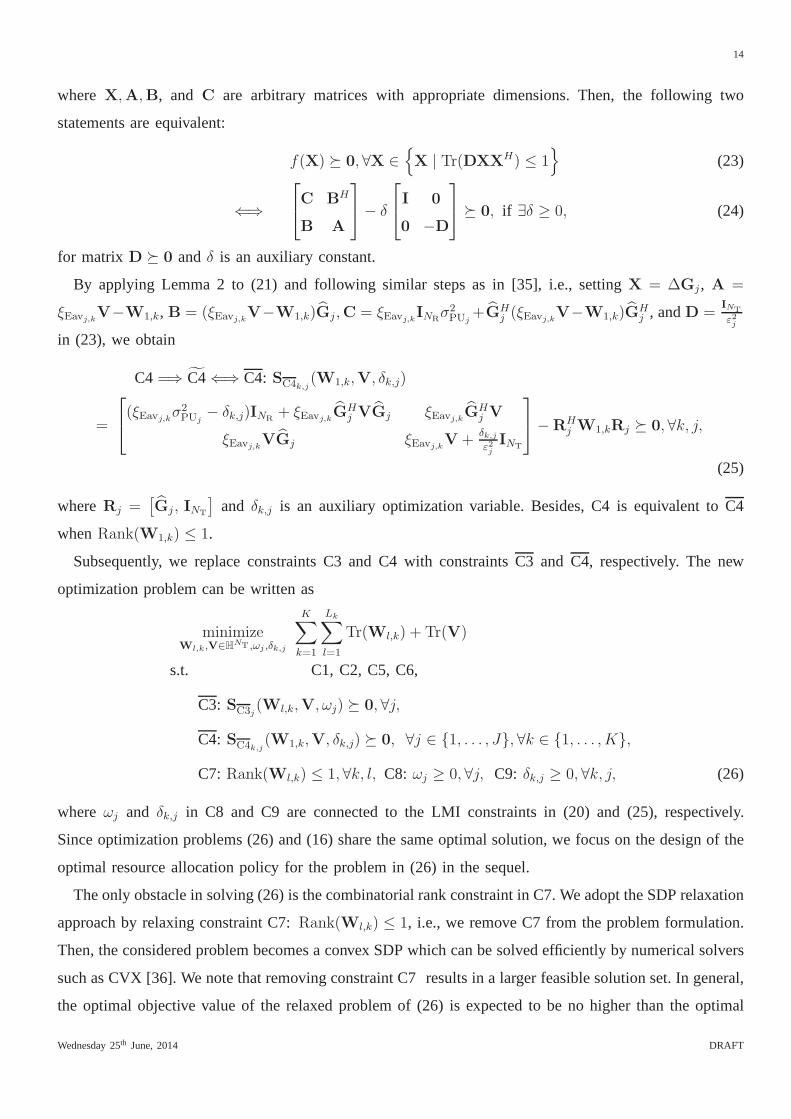
Subsequently, we replace constraints C3 and C4 with constraints C3 andC4, respectively. The new
optimization problem can be written as
minimizeWl,k,V∈HNT ,ωj ,δk,j
K∑
k=1
Lk∑
l=1
Tr(Wl,k) + Tr(V)
s.t. C1, C2, C5, C6,
C3: SC3j(Wl,k,V, ωj) 0, ∀j,
C4: SC4k,j(W1,k,V, δk,j) 0, ∀j ∈ 1, . . . , J, ∀k ∈ 1, . . . , K,
C7: Rank(Wl,k) ≤ 1, ∀k, l, C8: ωj ≥ 0, ∀j, C9: δk,j ≥ 0, ∀k, j, (26)
whereωj and δk,j in C8 and C9 are connected to the LMI constraints in (20) and (25), respectively.
Since optimization problems (26) and (16) share the same optimal solution, we focus on the design of the
optimal resource allocation policy for the problem in (26) in the sequel.
The only obstacle in solving (26) is the combinatorial rank constraint in C7. We adopt the SDP relaxation
approach by relaxing constraint C7:Rank(Wl,k) ≤ 1, i.e., we remove C7 from the problem formulation.
Then, the considered problem becomes a convex SDP which can be solved efficiently by numerical solvers
such as CVX [36]. We note that removing constraint C7 resultsin a larger feasible solution set. In general,
the optimal objective value of the relaxed problem of (26) isexpected to be no higher than the optimal
Wednesday 25th June, 2014 DRAFT

15
objective value of (16). However, if the obtained solutionWl,k for the relaxed problem admits a rank-one
matrix, this is also the optimal solution of the original problem in (16) and the adopted SDP relaxation
is tight. Subsequently, the optimalwl,k can be obtained by performing eigenvalue decomposition onWl,k
and selecting the principal eigenvector as the beamformingvector. However, it is known that in general
the constraint relaxation may not be tight andRank(Wl,k) > 1 may occur. In the following, we propose
a method for constructing an optimal solution of the relaxedversion of (26) with a rank-one matrix
Wl,k, ∀k, l.
B. Optimality Condition for SDP Relaxation
In this subsection, we first reveal the tightness of the proposed SDP relaxation. The existence of a rank-
one solution matrixWl,k for the relaxed SDP version of (26) is summarized in the following theorem
which is based on [37, Proposition 4.1].
Theorem 1:Suppose the optimal solution of the SDP relaxed version of (26) is denoted asW∗l,k,V
∗, ω∗j ,
δ∗k,j and∃k, l : Rank(W∗l,k) > 1. Then, there exists a feasible optimal solution of the SDP relaxed version
of (26), denoted asΛ , Wl,k, V, ωj, δk,j, with a rank-one matrixWl,k, i.e., Rank(Wl,k) = 1. This
optimal solution can be obtained by construction.
Proof: Please refer to Appendix B for the proof of Theorem 1 and the method for constructing the
optimal solution.
Since the optimal solution of the SDP relaxed version of (26)is a rank-one beamforming matrix
Wl,k, ∀l, k, by construction, the global optimum of (16) can be obtaineddespite the SDP relaxation.
C. Suboptimal Resource Allocation Schemes
The construction of the optimal solutionΛ with Rank(Wl,k) = 1 requires the optimal solution of
the dual version of the relaxed problem of (26), cf. variableY∗l,k in (36) in Appendix B. However, the
solution of the dual problem may not be provided by some numerical solvers and thus the construction
of a rank-one solution matrixWl,k may not be possible. In the following, we propose two suboptimal
resource allocation schemes based on the solution of the primal problem of the relaxed version of (26)
which do not require the solution of the dual problem.
1) Suboptimal Resource Allocation Scheme 1:A hybrid resource allocation scheme is proposed which
is based on the solution of the relaxed version of (26). We first solve (26) by SDP relaxation. The global
optimal solution of (26) is found if the obtained solutionW∗l,k is a rank-one matrix. Otherwise, we
construct a suboptimal solution setWsubl,k = wsub
l,k (wsubl,k )
H , wherewsubl,k is the eigenvector corresponding to
the principal eigenvalue of matrixW∗l,k. Then, we define a scalar optimization variablePl,k which controls
Wednesday 25th June, 2014 DRAFT

16
the power of the suboptimal beamforming matrix of layerl for secondary receiverk. Subsequently, a new
optimization problem is formulated as:
minimizeV∈HNT ,Pl,k,ωj ,δk,j
K∑
k=1
Lk∑
l=1
Tr(Pl,kWsubl,k ) + Tr(V)
s.t. C1:Tr(HkPl,kW
subl,k )
Tr(Hk
( K∑n 6=k
Ln∑l=1
Pl,nWsubl,n +
Lk∑m=l+1
Pj,kWsubj,k
))+ Tr(VHk) + σ2
sk
≥ Γreql,k , ∀l, ∀k,
C2:Tr(HtP1,kW
sub1,k )
Tr(Ht
( K∑n 6=k
n 6=t
Ln∑l=1
Pl,nWsubl,n +
Lk∑m=2
Pm,kWsubm,k
))+ Tr(VHt) + σ2
sk
≤ Γtol, ∀t 6= k, t ∈ 1, . . . , K,
C3: SC3j(Pl,kW
subl,k ,V, ωj) 0, ∀j,
C4: SC4k,j(P1,kW
sub1,k ,V, δk,j) 0, ∀j ∈ 1, . . . , J, ∀k ∈ 1, . . . , K,
C5: V 0, C6: Pl,k ≥ 0, C8: ωj ≥ 0, ∀j, C9: δk,j ≥ 0, ∀k, j. (27)
It can be shown that the above optimization problem is jointly convex with respect to the optimization
variables and thus can be solved by using efficient numericalsolvers. Besides, the solution of (27) also
satisfies the constraints of (16). In other words, the solution of (27) serves as a suboptimal solution for
(16).
2) Suboptimal Resource Allocation Scheme 2:The second proposed suboptimal resource allocation
scheme adopts a similar approach to solve the problem as suboptimal resource allocation scheme 1,
except for the choice of the suboptimal beamforming matrixWsubl,k whenRank(Wsub
l,k ) > 1. For scheme 2,
the choice of beamforming matrixWsubl,k is based on the rank-one Gaussian randomization scheme [38].
Specifically, we calculate the eigenvalue decomposition ofWl,k = Ul,kΘl,kUHl,k, whereUl,k andΘl,k are an
NT×NT unitary matrix and a diagonal matrix, respectively. Then, we adopt the suboptimal beamforming
vector wsubl,k = Ul,kΘ
1/2l,k ql,k,W
subl,k = Pl,kw
subl,k (w
subl,k )
H , whereql,k ∈ CNT×1 and ql,k ∼ CN (0, INT
).
Subsequently, we follow the same approach as in (27) for optimizing V, Pl,k, ωj, δk,j and obtain a
suboptimal rank-one solutionPl,kWsubl,k . Furthermore, we can execute scheme 2 repeatedly for different
realizations of the Gaussian distributed random vectorql,k such that the performance of scheme 2 can
be improved by selecting the bestwsubl,k = Ul,kΘ
1/2l,k ql,k over different trials at the expense of higher
computation complexity.
V. RESULTS
In this section, we study the system performance of the proposed resource allocation scheme via
simulations. There areK secondary receivers andJ primary receivers, which are uniformly distributed
Wednesday 25th June, 2014 DRAFT

17
TABLE I
SYSTEM PARAMETERS
Carrier center frequency 2.6 GHz
Small-scale fading distribution Rayleigh fading
Large-scale fading model Non-line-of-sight, urban micro scenario, 3GPP [39]
Cell radius 500 meters
Transceiver antenna gain 0 dBi
Thermal noise power,σ2s , σ2
PUj−107.35 dBm
Maximum tolerable received interference power at primary
receiverj, PIj
−110.35 dBm
Minimum requirement on the SINR of layers[Γreq1, Γreq
2] [ΓBase, ΓBase + 3] dB
Maximum tolerable SINR for information decoding at unin-
tended primary receivers,Γtol
0 dB
Maximum tolerable data rate at primary receiver,REavj,k1 bit/s/Hz
in the range between a reference distance of30 meters and the maximum cell radius of500 meters. We
assume that there is always onepremium secondary receiverand the secondary transmitter is required to
guarantee the SINR of all video layers for this receiver. On the contrary, the transmitter guarantees only
the SINR of the first layer for the remainingK − 1 regular receivers. We assume that the video signal
of each secondary receiver is encoded into two layers. For the sake of illustration, the minimum required
SINR of the first layer and the second layer are denoted asΓBase andΓBase + 3, respectively. Also, we
solve the optimization problem in (15) via SDP relaxation and obtain the average system performance by
averaging over different channel realizations. In the sequel, we define the normalized maximum channel
estimation error of primary receiverj as σ2PUj
=ε2j
‖Gj‖2Fwith σ2
PUa= σ2
PUb, ∀a, b ∈ 1, . . . , J. Unless
specified otherwise, we assume a normalized maximum channelestimation error ofσ2PUj
= 0.05, ∀j for
primary receiverj and there areNR = 2 receive antennas at each primary receiver. Besides, the maximum
tolerable interference power at the primary receivers is set to PIj = −110.35 dBm, ∀j ∈ 1, . . . , J. The
parameters adopted for our simulation are summarized in Table I.
A. Average Total Transmit Power versus Minimum Required SINR
Figure 2 depicts the average total transmit power versus theminimum required SINR of the base
layer, ΓBase, for NT = 8 transmit antennas,K = 2 secondary receivers,J = 2 primary receivers, and
different resource allocation schemes. It can be observed that the average total transmit power for the
proposed schemes is a monotonically increasing function with respect to the minimum required SINR
of the base layer. Clearly, the transmitter has to allocate more power to the information signal as the
Wednesday 25th June, 2014 DRAFT

18
3 4 5 6 7 8 9 10 11 1218
20
22
24
26
28
30
32
34
36
ΓBase
(dB)
Ave
rage
tota
l tra
nsm
it po
wer
(dB
m)
Optimal schemeSuboptimal scheme 1Suboptimal scheme 2Baseline scheme 1Baseline scheme 2
Baseline scheme 2
Proposed schemes
Baseline scheme 1
Performance gain
Fig. 2. Average total transmit power (dBm) versus minimum required SINR of the base layer,ΓBase, for NT = 8 transmit antennas,K = 2
secondary receivers,J = 2 primary receivers, and different resource allocation schemes. The double-sided arrow indicates the performance
gain achieved by the proposed schemes compared to single-layer transmission adopted in baseline scheme 1.
SINR requirement gets more stringent. Besides, the two proposed suboptimal resource allocation schemes
approach the optimal performance. In fact, the proposed suboptimal schemes exploit the possibility of
achieving the global optimal solution via SDP relaxation.
For comparison, Figure 2 also contains results for the average total transmit power of two baseline
resource allocation schemes. For baseline scheme 1, we adopt single-layer transmission for delivering the
multiuser video signals. In particular, we solve the corresponding robust optimization problem with respect
to Wl,k,V, ωj, δk,j subject to constraints C1 – C9 via SDP relaxation. The minimum required SINR
for decoding the single-layer video information at the secondary receivers for baseline scheme 1 is set to
ΓSinglereqk
= 2∑Lk
l=1log2(1+Γreql,k
) − 1. In baseline scheme 2, we consider a naive layered video transmission.
Specifically, the secondary transmitter treats the estimated CSI of the primary receivers as perfect CSI and
exploits it for resource allocation. In other words, robustness against CSI errors is not provided by baseline
scheme 2. It can be observed that baseline scheme 1 requires ahigher total average power compared to
the proposed power allocation schemes. This can be attributed to the fact that single-layer transmission
does not posses theself-protectingstructure for providing secure communication that layeredtransmission
has. As a result, a higher transmit power is required in baseline scheme 1 to ensure secure video delivery.
On the other hand, it is expected that for baseline scheme 2, the average transmit power is lower than that
of the proposed scheme. This is due to the fact that the secondary transmitter assumes the available CSI
Wednesday 25th June, 2014 DRAFT

19
1 2 3 4 520
25
30
35
Number of secondary users (K)
Ave
rage
tota
l tra
nsm
it po
wer
(dB
m)
Optimal schemeSuboptimal scheme 1Suboptimal scheme 2Baseline scheme 1Baseline scheme 2
Baseline scheme 1
Baseline scheme 2
Performance gain
Proposed schemes
Fig. 3. Average total transmit power (dBm) versus the numberof secondary receivers for a minimum required SINR of the base layer
of ΓBase = 5 dB, J = 1 primary receiver,NT = 8 transmit antennas, and different resource allocation schemes. The double-sided arrow
indicates the performance gain achieved by the proposed schemes compared to single-layer transmission adopted in baseline scheme 1.
is perfect and transmits with insufficient power for providing secure communication. The next sections
will show that baseline scheme 2 cannot meet the QoS requirements regarding communication security
and interference leakage to the primary network.
B. Average Total Transmit Power versus Number of Secondary Receivers
Figure 3 illustrates the average total transmit power versus the number of secondary receivers for
a minimum required SINR of the base layer ofΓBase = 5 dB, J = 1 primary receiver,NT = 8
transmit antennas, and different resource allocation schemes. It can be seen that the average total transmit
power increases with the number of secondary receivers for all resource allocation schemes. In fact, the
requirement of secure communication becomes more difficultto meet if there are more secondary receivers
in the system. Besides, more degrees of freedom are utilizedfor reducing mutual interference between the
secondary receivers which leads to a less efficient power allocation. Hence, a higher total transmit power
is required to meet the target QoS.
On the other hand, the two proposed suboptimal resource allocation schemes achieve a similar perfor-
mance as the optimal resource allocation. Also, the proposed schemes provide substantial power savings
compared to baseline scheme 1 forK > 1 due to the adopted layered transmission. In particular, the
performance gap between the proposed schemes and baseline scheme 1 increases with increasing numbers
Wednesday 25th June, 2014 DRAFT

20
6 7 8 9 10 11 1220
21
22
23
24
25
26
27
28
29
Number of transmit antennas (NT)
Ave
rage
tota
l tra
nsm
it po
wer
(dB
m)
Optimal schemeSuboptimal scheme 1Suboptimal scheme 2Baseline scheme 1Baseline scheme 2
Proposed schemes
Baseline scheme 2
Performance gain
Baseline scheme 1
Fig. 4. Average total transmit power (dBm) versus the numberof transmit antennas,NT, for a minimum required SINR of the base layer
of ΓBase = 5 dB, J = 2 primary receivers,K = 2 secondary receivers, and different resource allocation schemes. The double-sided arrow
indicates the performance gain achieved by the proposed schemes compared to single-layer transmission adopted in baseline scheme 1.
of primary receivers. In other words, layered transmissionis effective for reducing the transmit power in
multi-receiver environments. As for baseline scheme 2, although it consumes less transmit power compared
to the optimal scheme, it cannot guarantee any QoS in communication secrecy and interference to the
primary receivers, cf. Figures 5 – 7.
C. Average Total Transmit Power versus Number of Antennas
Figure 4 shows the average total transmit power versus the number of transmit antennas,NT, for a
minimum required SINR of the base layer ofΓBase = 5 dB, J = 2 primary receivers,K = 2 secondary
receivers, and different resource allocation schemes. It is expected that the average total transmit power
decreases for all resource allocation schemes with increasing number of transmit antennas. This is because
extra degrees of freedom can be exploited for resource allocation when more antennas are available at
the transmitter. Specifically, with more antennas, the direction of beamforming matrixWl,k can be more
accurately steered towards the secondary receivers which reduces both the power consumption at the
secondary transmitter and the power leakage to the primary receivers. On the other hand, the proposed
schemes provide substantial power savings compared to baseline scheme 1 for all considered scenarios
because of the adopted layered transmission. Besides, baseline scheme 2 consumes less transmit power
compared to the optimal scheme again. Although baseline scheme 2 can exploit the extra degrees of
Wednesday 25th June, 2014 DRAFT

21
3 4 5 6 7 8 9 10 11 120
1
2
3
4
5
6
7
8
9
ΓBase
(dB)
Ave
rage
sec
recy
rat
e (b
it/s/
Hz)
Minimum required secrecy rate
Optimal scheme
Suboptimal scheme 1
Suboptimal scheme 2
Baseline scheme 1
Baseline scheme 2
Proposed schemes
Baseline scheme 1
Baseline scheme 2Minimum required secrecy rate
Fig. 5. Average secrecy rate (bit/s/Hz) of the base layer versus the minimum required SINR of the base layer,ΓBase, for NT = 8 transmit
antennas,K = 2 secondary receivers,J = 2 primary receivers, and different resource allocation schemes.
freedom offered by the increasing number of antennas, it is unable to protect the primary receivers from
interference and cannot guarantee communication securitydue to the imperfection of the CSI, cf. Figures
5 – 7.
D. Average Secrecy Rate
Figure 5 depicts the average secrecy rate of the base layer versus the minimum required SINR of the base
layer forNT = 8 transmit antennas,K = 2 secondary receivers,J = 2 primary receivers, and different
resource allocation schemes. Despite the imperfection of the CSI, the proposed optimal resource allocation
scheme and the two suboptimal resource allocation schemes are able to guarantee the minimum secrecy
rate required by constraints C2 and C4 in every time instant,because of the adopted robust optimization
framework. On the other hand, baseline scheme 1 achieves an exceedingly high average secrecy rate since
the entire video information is encoded in the first layer. The superior secrecy rate performance of baseline
scheme 1 comes at the expense of an exceedingly high transmitpower, cf. Figure 2. In the lowΓBase
regime, even though baseline scheme 2 is able to meet the minimum secrecy rate requirement on average,
we emphasize that baseline scheme 2 is unable to fulfill the requirement for all channel realizations,
i.e., secure communication is not ensured. Besides, in the high ΓBase regime, in contrast to the proposed
schemes, baseline scheme 2 cannot even satisfy the minimum secrecy rate requirement on average.
Wednesday 25th June, 2014 DRAFT

22
3 4 5 6 7 8 9 10 11 12−118
−116
−114
−112
−110
−108
−106
ΓBase
(dB)
Ave
rage
rec
eive
d in
terf
eren
ce p
ower
(dB
m)
Optimal schemeSuboptimal scheme 1Suboptimal scheme 2Baseline scheme 1Baseline scheme 2Maximum tolerable interference
Baseline scheme 1
Baseline scheme 2
Proposed schemes
Maximum tolerable interference
Fig. 6. Average received interference power (dBm) at each primary receiver versus the minimum required SINR of the base layer,ΓBase,
for NT = 8 transmit antennas,K = 2 secondary receivers,J = 2 primary receivers, and different resource allocation schemes.
E. Average Interference Power
Figure 6 depicts the average received interference power ateach primary receiver versus the minimum
required SINR of the base layerΓBase, for NT = 8 transmit antennas,K = 2 secondary receivers,
J = 2 primary receivers, and different resource allocation schemes. As can be observed, the proposed
optimal resource allocation scheme and the two suboptimal resource allocation schemes are able to control
their transmit power such that the received interference powers at the primary receivers are below the
maximum tolerable interference threshold. Similar results can be observed for baseline scheme 1 as robust
optimization is also adopted in this case. As for baseline scheme 2, although the average interference
received by each primary receiver is below the maximum tolerable threshold forΓBase ≤ 6 dB, baseline
scheme 2 cannot meet the interference requirement for all channel realizations. Besides, as the value of
ΓBase increases, the received interference power at each primaryreceiver increases significantly compared
to the proposed schemes. For high values ofΓBase, the average received interference at each primary
receiver for baseline scheme 2 exceeds the maximum tolerable interference limit.
Figure 7 shows the average received interference power at each primary receiver versus the number of
secondary receiversK for a minimum required SINR of the base layer ofΓBase = 5 dB, NT = 8 transmit
antennas,J = 1 primary receiver, and different resource allocation schemes. It can be observed that the
received interference power at each primary receiver increases with the number of secondary receivers
Wednesday 25th June, 2014 DRAFT

23
1 2 3 4 5−117
−116
−115
−114
−113
−112
−111
−110
Number of secondary users (K)
Ave
rage
rec
eive
d in
terf
eren
ce p
ower
(dB
m)
Optimal scheme
Suboptimal scheme 1
Suboptimal scheme 2
Baseline scheme 1
Baseline scheme 2
Maximum tolerable interference
Baseline scheme 1
Maximum tolerable interference
Proposed schemes
Baseline scheme 2
Fig. 7. Average received interference power (dBm) at each primary receiver versus the number of secondary receivers,K, for a minimum
required SINR of the base layer ofΓBase = 5 dB, NT = 8 transmit antennas,J = 1 primary receiver, and different resource allocation
schemes.
since the secondary transmitter is required to transmit with higher power for serving extra receivers.
Besides, the proposed schemes and baseline scheme 1 are ableto control the interference leakage to the
primary network for any number of secondary receivers. However, baseline scheme 2 fails to properly
control the transmit power and cannot satisfy the maximum tolerable received interference limit for all
channel realizations, due to the non-robust resource allocation algorithm design.
VI. CONCLUSIONS
In this paper, we studied the robust resource allocation algorithm design for layered transmit power
minimization for secure layered video transmission in secondary CR networks. The algorithm design was
formulated as a non-convex optimization problem taking into account the communication secrecy for
transmission to the secondary receivers, the imperfectionof the CSI of the primary receivers, and the
interference leakage to the primary network. We showed thatthe global optimal solution of the considered
non-convex optimization problem can be constructed based on the primal and the dual solutions of the
SDP relaxed problem. Furthermore, two suboptimal resourceallocation schemes were proposed for the
case when the dual problem solution is unavailable for construction of the optimal solution. Simulation
results unveiled the power savings enabled by the self-protecting structure of layered transmission and the
Wednesday 25th June, 2014 DRAFT

24
robustness of our proposed optimal scheme against the imperfect knowledge of the CSI of the primary
receivers.
APPENDIX
A. Proof of Proposition 1
Constraint C4 is non-convex due to the log-determinant function and the coupling between optimization
variablesWl,k andV. In light of the intractability of the constraint, we first establish a lower bound on
the left hand side of C4. Then, we will reveal the tightness ofthe proposed lower bound. We now start
the proof by rewriting C4 as
C4: log2 det(INR
+Σ−1j GH
j W1,kGj
)≤ REavj,k (28a)
(a)⇐⇒ det
(INR
+Σ−12
j GHj W1,kGjΣ
−12
j
)≤ 1 + ξEavj,k , (28b)
where(a) is due to the fact thatΣj ≻ 0 anddet(I+AB) = det(I+BA) holds for any choice of matrices
A andB. Then, we introduce the following lemma which provides a lower bound on the left hand side
of (28b).
Lemma 3:For any square matrixA 0, we have the following inequality [35], [40]:
det(I+A) ≥ 1 + Tr(A), (29)
where equality holds if and only ifRank(A) ≤ 1.
Exploiting Lemma 3, the left hand side of (28b) is lower bounded by
det(INR+Σ
−12
j GHj W1,kGjΣ
−12
j ) ≥ 1 + Tr(Σ−12
j GHj W1,kGjΣ
−12
j ). (30)
Subsequently, by combining equations (28) and (30), we havethe following implications
(28a)⇐⇒ (28b) =⇒ Tr(Σ−12
j GHj W1,kGjΣ
−12
j ) ≤ ξEavj,k (31a)
(b)=⇒ λmax(Σ
−12
j GHj W1,kGjΣ
−12
j ) ≤ ξEavj,k (31b)
⇐⇒ Σ−12
j GHj W1,kGjΣ
−12
j ξEavj,kINR(31c)
⇐⇒ GHj W1,kGj ξEavj,kΣj , (31d)
where (b) is due toTr(A) ≥ λmax(A) for a positive semidefinite square matrixA 0. We note that
Tr(A) ≥ λmax(A) holds if and only ifRank(A) ≤ 1. Thus, in general, the set spanned by (28a) is a
subset of the set spanned by (31d). Besides, (28a) is equivalent to (31d) whenRank(W1,k) ≤ 1, ∀k.
Wednesday 25th June, 2014 DRAFT
25
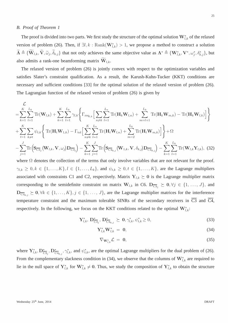
B. Proof of Theorem 1
The proof is divided into two parts. We first study the structure of the optimal solutionW∗l,k of the relaxed
version of problem (26). Then, if∃l, k : Rank(W∗l,k) > 1, we propose a method to construct a solution
Λ , Wl,k, V, ωj, δk,j that not only achieves the same objective value asΛ∗ , W∗l,k,V
∗, ω∗j , δ
∗k,j, but
also admits a rank-one beamforming matrixWl,k.
The relaxed version of problem (26) is jointly convex with respect to the optimization variables and
satisfies Slater’s constraint qualification. As a result, the Karush-Kuhn-Tucker (KKT) conditions are
necessary and sufficient conditions [33] for the optimal solution of the relaxed version of problem (26).
The Lagrangian function of the relaxed version of problem (26) is given by
L
=K∑
k=1
Lk∑
l=1
Tr(Wl,k) +K∑
k=1
Lk∑
l=1
γl,k
Γreql,k
[∑
n 6=k
Ln∑
l=1
Tr(HkWl,n) +
Lk∑
m=l+1
Tr(HkWm,k)− Tr(HkWl,k)]
+
K∑
t=1
∑
k 6=t
ψt,k
Tr(HtW1,k)− Γtol
[ K∑
n 6=k
Ln∑
l=1
Tr(HtWl,n) +
Lk∑
m=2
Tr(HtWm,k)]
+Ω
−J∑
j=1
Tr(SC3j
(Wl,k,V, ωj
)DC3j
)−
K∑
k=1
J∑
j=1
Tr(SC4k,j
(W1,k,V, δk,j
)DC4k,j
)−
K∑
k=1
Lk∑
l=1
Tr(Wl,kYl,k), (32)
whereΩ denotes the collection of the terms that only involve variables that are not relevant for the proof.
γl,k ≥ 0, k ∈ 1, . . . , K, l ∈ 1, . . . , Lk, and ψt,k ≥ 0, t ∈ 1, . . . , K, are the Lagrange multipliers
associated with constraints C1 and C2, respectively. Matrix Yl,k 0 is the Lagrange multiplier matrix
corresponding to the semidefinite constraint on matrixWl,k in C6. DC3j 0, ∀j ∈ 1, . . . , J, and
DC4k,j 0, ∀k ∈ 1, . . . , K, j ∈ 1, . . . , J, are the Lagrange multiplier matrices for the interference
temperature constraint and the maximum tolerable SINRs of the secondary receivers inC3 and C4,
respectively. In the following, we focus on the KKT conditions related to the optimalW∗l,k:
Y∗l,k, D
∗C3j, D∗
C4k,j 0, γ∗l,k, ψ
∗t,k ≥ 0, (33)
Y∗l,kW
∗l,k = 0, (34)
∇W∗l,kL = 0, (35)
whereY∗l,k,D
∗C3j,D∗
C4k,j, γ∗l,k, andψ∗
t,k, are the optimal Lagrange multipliers for the dual problem of (26).
From the complementary slackness condition in (34), we observe that the columns ofW∗l,k are required to
lie in the null space ofY∗l,k for W∗
l,k 6= 0. Thus, we study the composition ofY∗l,k to obtain the structure
Wednesday 25th June, 2014 DRAFT
26
of W∗l,k. The KKT condition in (35) leads to
Y∗l,k = Al,k −
[∑
t<l
γ∗t,kΓreqt,k − γ∗l,k
]Hk (36)
whereAl,k =
Bl,k +∑t6=k
ψ∗t,kHt +
K∑k=1
J∑j=1
RjD∗C4k,j
RHj if l = 1
Bl,k −∑t6=k
ψ∗t,kΓtolHt otherwise
(37)
andBl,k =∑
m6=k
Lm∑
r=1
γ∗r,mΓreqr,m − Γtol
[∑
t6=k
∑
n 6=t,k
ψ∗t,nHt
]+
J∑
j=1
UgjD∗
C3jUH
gj. (38)
Without loss of generality, we definerl,k = Rank(A∗l,k) and the orthonormal basis of the null space of
A∗l,k as Υ ∈ CNT×(NT−rl,k) such thatA∗
l,kΥl,k = 0 and Rank(Υl,k) = NT − rl,k. Let φτl,k∈ CNT×1,
1 ≤ τl,k ≤ NT − rl,k, denote theτl,k-th column ofΥl,k. By exploiting [37, Proposition 4.1], it can be
shown that[∑
t<l γ∗t,kΓreqt,k − γ∗l,k
]Hk 6= 0 andHkΥl,k = 0 for the optimal solution. Besides, we can
express the optimal solution ofW∗l,k as
W∗l,k =
NT−rl,k∑
τl,k=1
ατl,kφτl,kφH
τl,k+ fl,kul,ku
Hl,k︸ ︷︷ ︸
rank-one
, (39)
whereατl,k ≥ 0, ∀τl,k ∈ 1, . . . , NT− rl,k, andfl,k > 0 are positive scalars andul,k ∈ CNT×1, ‖ul,k‖ = 1,
satisfiesuHl,kΥl,k = 0. In particular, we have the following equality:
HkW∗l,k =
NT−rl,k∑
τl,k=1
Hkατl,kφτl,kφH
τl,k
︸ ︷︷ ︸=0
+Hkfl,kul,kuHl,k. (40)
In the second part of the proof, we construct another solution Λ , Wl,k, V, ωj, δk,j based on (40).
Suppose there exist pair ofl andk such thatRank(W∗l,k) > 1. Let
Wl,k = fl,kul,kuHl,k = W∗
l,k −
NT−rl,k∑
τl,k=1
αl,kφτl,kφH
τl,k, (41)
V = V∗ +
NT−rl,k∑
τl,k=1
αl,kφτl,kφH
τl,k, ωj = δ∗j , δk,j = δ∗k,j.
Then, we substitute the constructed solutionΛ into the objective function and the constraints in (26) which
Wednesday 25th June, 2014 DRAFT

27
yields
Objective value:K∑
k=1
Lk∑
l=1
Tr(Wl,k) + Tr(V) =K∑
k=1
Lk∑
l=1
Tr(W∗l,k) + Tr(V∗) (42)
C1:Tr(HkWl,k)
Tr(Hk
( K∑n 6=k
Ln∑r=1
W∗r,n +
Lk∑m=l+1
W∗j,k
))+ Tr(HkV) + σ2
sk
=Tr
(Hk
(W∗
l,k −∑NT−rl,k
τl,k=1 αl,kφτl,kφH
τl,k
))
Tr(Hk
( K∑n 6=k
Ln∑r=1
W∗r,n +
Lk∑m=l+1
W∗j,k
))+ Tr(Hk(V∗ +
∑NT−rl,kτl,k=1 αl,kφτl,k
φHτl,k
)) + σ2sk
=Tr(HkW
∗l,k)
Tr(Hk
( K∑n 6=k
Ln∑r=1
W∗r,n +
Lk∑m=l+1
W∗j,k
))+ Tr(HkV∗) + σ2
sk
≥ Γreqk , ∀l, k,
C2:Tr(HtW1,k)
Tr(Ht
( K∑n 6=k
n 6=t
Ln∑r=1
W∗r,n +
Lk∑m=2
W∗m,k
))+ Tr(VHt) + σ2
sk
≤Tr(HtW
∗1,k)
Tr(Ht
( K∑n 6=k
n 6=t
Ln∑r=1
W∗r,n +
Lk∑m=2
W∗m,k
))+ Tr(V∗Ht) + σ2
sk
≤ Γtol, ∀t 6= k, t ∈ 1, . . . , K,
C3: SC3j(Wl,k, V, ωj) SC3j
(W∗l,k,V
∗, ω∗j ) +UH
gj
[ NT−rl,k∑
τl,k=1
αl,kφτl,kφH
τl,k
]Ugj
0, ∀j ∈ 1, . . . , J,
C4: SC4k,j(Wl,k, V, ωj) SC4k,j
(W∗l,k,V
∗, δ∗k,j) +RHj
[ NT−rl,k∑
τl,k=1
αl,kφτl,kφH
τl,k
]Rj 0, ∀k, j,
C5: Wl,k 0, C6:V 0, C8: ωj = ω∗j ≥ 0, C9: δi,k = δ∗j,k ≥ 0.
It can be seen from (42) that the constructed solution set achieves the same optimal value as the optimal
solution while satisfying all the constraints. Thus,Λ is also an optimal solution of (26). Besides, the
constructed beamforming matrixWl,k is a rank-one matrix, i.e.,Rank(Wl,k) = 1. On the other hand, we
can obtain the values offl,k andαl,k in (41) by substituting the variables in (41) into the relaxed version
of (26) and solving the resulting convex optimization problem for fl,k andαl,k.
If there is more than one pair ofl andk such thatRank(Wl,k) > 1, then we employ (41) more than
once and construct the rank-one solution by handling the non-rank-one beamforming matrices one by one.
Besides, the ordering of thel andk pairs in constructing the optimal solution does not affect to the optimal
objective value.
Wednesday 25th June, 2014 DRAFT

28
REFERENCES
[1] D. W. K. Ng, R. Schober, and H. Alnuweiri, “Power EfficientMISO Beamforming for Secure Layered Transmission,” inProc. IEEE
Wireless Commun. and Networking Conf., Apr. 2014.
[2] D. Tse and P. Viswanath,Fundamentals of Wireless Communication, 1st ed. Cambridge University Press, 2005.
[3] D. W. K. Ng, E. Lo, and R. Schober, “Energy-Efficient Resource Allocation in OFDMA Systems with Large Numbers of Base Station
Antennas,”IEEE Trans. Wireless Commun., vol. 11, pp. 3292–3304, Sep. 2012.
[4] K. Bhattad, K. Narayanan, and G. Caire, “On the Distortion SNR Exponent of Some Layered Transmission Schemes,”IEEE Trans.
Inf. Theory, vol. 54, pp. 2943–2958, Jul. 2008.
[5] D. Song and C. W. Chen, “Scalable H.264/AVC Video Transmission Over MIMO Wireless Systems with Adaptive Channel Selection
Based on Partial Channel Information,”IEEE Trans. Circuits Syst. Video Technol., vol. 17, pp. 1218–1226, Sep. 2007.
[6] J. Xuan, S. H. Lee, and S. Vishwanath, “Broadcast Strategies for MISO and Multiple Access Channels,” inProc. IEEE Personal, Indoor
and Mobile Radio Commun. Sympos., Sep. 2007, pp. 1–4.
[7] “Facilitating Opportunities for Flexible, Efficient, and Reliable Spectrum Use Employing Cognitive Radio Technologies,” Federal
Communications Commission, Tech. Rep., 2002, FCC 02-155.
[8] Y.-C. Liang, K.-C. Chen, G. Li, and P. Mahonen, “Cognitive Radio Networking and Communications: An Overview,”IEEE Trans. Veh.
Technol., vol. 60, pp. 3386–3407, Sep. 2011.
[9] G. Ganesan and Y. Li, “Cooperative Spectrum Sensing in Cognitive Radio, Part I: Two User Networks,”IEEE Trans. Wireless Commun.,
vol. 6, pp. 2204–2213, Jun. 2007.
[10] J. Ma, G. Zhao, and Y. Li, “Soft Combination and Detection for Cooperative Spectrum Sensing in Cognitive Radio Networks,” IEEE
Trans. Wireless Commun., vol. 7, pp. 4502–4507, Nov. 2008.
[11] Y.-C. Liang, Y. Zeng, E. Peh, and A. T. Hoang, “Sensing-Throughput Tradeoff for Cognitive Radio Networks,”IEEE Trans. Wireless
Commun., vol. 7, pp. 1326–1337, Apr. 2008.
[12] Z. Quan, S. Cui, and A. Sayed, “Optimal Linear Cooperation for Spectrum Sensing in Cognitive Radio Networks,”IEEE J. Select.
Areas Commun., vol. 2, pp. 28–40, Feb. 2008.
[13] H. Islam, Y.-C. Liang, and A. T. Hoang, “Joint Beamforming and Power Control in the Downlink of Cognitive Radio Networks,” in
Proc. IEEE Wireless Commun. and Networking Conf., Apr. 2007, pp. 21–26.
[14] L. Zhang, Y.-C. Liang, and Y. Xin, “Joint Beamforming and Power Allocation for Multiple Access Channels in Cognitive Radio
Networks,” IEEE J. Select. Areas Commun., vol. 26, pp. 38–51, Jan. 2008.
[15] L. Zhang, Y.-C. Liang, Y. Xin, and H. Poor, “Robust Cognitive Beamforming with Partial Channel State Information,”IEEE Trans.
Wireless Commun., vol. 8, pp. 4143–4153, Aug. 2009.
[16] G. Zheng, K.-K. Wong, and B. Ottersten, “Robust Cognitive Beamforming With Bounded Channel Uncertainties,”IEEE Trans. Signal
Process., vol. 57, pp. 4871–4881, Dec. 2009.
[17] D. W. K. Ng, E. S. Lo, and R. Schober, “Multi-Objective Resource Allocation for Secure Communication in Cognitive Radio
Networks with Wireless Information and Power Transfer,”Submitted for possible journal publication, Mar. 2014. [Online]. Available:
http://arxiv.org/abs/1403.0054
[18] Y. Fallah, H. Mansour, S. Khan, P. Nasiopoulos, and H. Alnuweiri, “A Link Adaptation Scheme for Efficient Transmission of H.264
Scalable Video Over Multirate WLANs,”IEEE Trans. Circuits Syst. Video Technol., vol. 18, pp. 875–887, Jun. 2008.
[19] B. Barmada, M. Ghandi, E. Jones, and M. Ghanbari, “Prioritized Transmission of Data Partitioned H.264 Video with Hierarchical
QAM,” IEEE Signal Process. Lett., vol. 12, pp. 577–580, Aug. 2005.
[20] W. Mesbah, M. Shaqfeh, and H. Alnuweiri, “Jointly Optimal Rate and Power Allocation for Multilayer Transmission,”IEEE Trans.
Commun., vol. 13, pp. 834–845, Feb. 2014.
[21] M. Shaqfeh, W. Mesbah, and H. Alnuweiri, “Utility Maximization for Layered Transmission Using the Broadcast Approach,” IEEE
Trans. Wireless Commun., vol. 11, pp. 1228–1238, Mar. 2012.
[22] A. D. Wyner, “The Wire-Tap Channel,” Tech. Rep., Oct. 1975.
Wednesday 25th June, 2014 DRAFT

29
[23] I. Csiszar and J. Korner, “Broadcast Channels with Confidential Messages,”IEEE Trans. Inf. Theory, vol. 24, pp. 339–348, May 1978.
[24] S. K. Leung-Yan-Cheong and M. E. Hellman, “The GaussianWire-Tap Channel,”IEEE Trans. Inf. Theory, vol. 24, pp. 451 – 456, Jul.
1978.
[25] Q. Li and W.-K. Ma, “Multicast Secrecy Rate Maximization for MISO Channels with Multiple Multi-Antenna Eavesdroppers,” in Proc.
IEEE Intern. Commun. Conf., Jun. 2011, pp. 1–5.
[26] S. Goel and R. Negi, “Guaranteeing Secrecy using Artificial Noise,” IEEE Trans. Wireless Commun., vol. 7, pp. 2180–2189, Jun. 2008.
[27] D. W. K. Ng, E. S. Lo, and R. Schober, “Secure Resource Allocation and Scheduling for OFDMA Decode-and-Forward RelayNetworks,”
IEEE Trans. Wireless Commun., vol. 10, pp. 3528–3540, Aug. 2011.
[28] D. Ng, E. Lo, and R. Schober, “Energy-Efficient ResourceAllocation for Secure OFDMA Systems,”IEEE Trans. Veh. Technol., vol. 61,
pp. 2572–2585, Jul. 2012.
[29] G. Zheng, K. K. Wong, and T. S. Ng, “Robust Linear MIMO in the Downlink: A Worst-Case Optimization with Ellipsoidal Uncertainty
Regions,”EURASIP J. Adv. Signal Process., vol. 2008, 2008, Article ID 609028.
[30] C. Shen, T.-H. Chang, K.-Y. Wang, Z. Qiu, and C.-Y. Chi, “Distributed Robust Multicell Coordinated Beamforming With Imperfect
CSI: An ADMM Approach,” IEEE Trans. Signal Process., vol. 60, pp. 2988–3003, Jun. 2012.
[31] N. Vucic and H. Boche, “Robust QoS-Constrained Optimization of Downlink Multiuser MISO Systems,”IEEE Trans. Signal Process.,
vol. 57, pp. 714–725, Feb. 2009.
[32] D. W. K. Ng, E. S. Lo, and R. Schober, “Robust Beamformingfor Secure Communication in Systems with Wireless Information and
Power Transfer,”IEEE Trans. Wireless Commun., vol. PP, no. 99, 2014.
[33] S. Boyd and L. Vandenberghe,Convex Optimization. Cambridge University Press, 2004.
[34] Z. Q. Luo, J. Sturm, and S. Zhang, “Multivariate Nonnegative Quadratic Mappings,”SIAM J. Optim., vol. 14, pp. 1140–1162, Jul. 2004.
[35] Q. Li and W.-K. Ma, “Spatially Selective Artificial-Noise Aided Transmit Optimization for MISO Multi-Eves SecrecyRate
Maximization,” IEEE Trans. Signal Process., vol. 61, pp. 2704–2717, May 2013.
[36] M. Grant and S. Boyd, “CVX: Matlab Software for Disciplined Convex Programming, version 2.0 Beta,” [Online] https://cvxr.com/cvx,
Sep. 2012.
[37] L. Liu, R. Zhang, and K.-C. Chua, “Secrecy Wireless Information and Power Transfer with MISO Beamforming,”IEEE Trans. Signal
Process., vol. 62, pp. 1850–1863, Apr. 2014.
[38] N. Sidiropoulos, T. Davidson, and Z.-Q. Luo, “TransmitBeamforming for Physical-Layer Multicasting,”IEEE Trans. Signal Process.,
vol. 54, pp. 2239–2251, Jun. 2006.
[39] “Evolved Universal Terrestrial Radio Access (E-Utra); Further Advancements for E-Utra Physical Layer Aspects,”3GPP TR 36.814
V9.0.0 (2010-03), Tech. Rep.
[40] Q. Li and W.-K. Ma, “Optimal and Robust Transmit Designsfor MISO Channel Secrecy by Semidefinite Programming,”IEEE Trans.
Signal Process., vol. 59, pp. 3799–3812, May 2011.
Wednesday 25th June, 2014 DRAFT