1-s2.0-s0360319913017163-main.pdf
TRANSCRIPT

ww.sciencedirect.com
i n t e r n a t i o n a l j o u r n a l o f h y d r o g e n en e r g y 3 8 ( 2 0 1 3 ) 1 2 7 9 5e1 2 8 0 2
Available online at w
journal homepage: www.elsevier .com/locate/he
Optimization of carbon fiber usage in Type 4hydrogen storage tanks for fuel cell automobiles
H.S. Roh, T.Q. Hua*, R.K. Ahluwalia
Argonne National Laboratory, Argonne, IL 60439, USA
a r t i c l e i n f o
Article history:
Received 25 February 2013
Received in revised form
20 June 2013
Accepted 5 July 2013
Available online 14 August 2013
Keywords:
Finite element analysis
Type IV composite pressure vessels
Hydrogen storage
* Corresponding author. Argonne National La252 3296.
E-mail address: [email protected] (T.Q. Hua).0360-3199/$ e see front matter Copyright ªhttp://dx.doi.org/10.1016/j.ijhydene.2013.07.0
a b s t r a c t
Finite element (FE) analysis of a filament wound 700-bar compressed hydrogen storage
Type 4 tank is presented. Construction of the FE model was derived from an initial netting
analysis to determine the optimal dome shape, winding angle, and helical and hoop layer
thicknesses. The FE model was then used to predict the performance of the composite tank
subject to the operating requirements and design assumptions, and to provide guidance for
design optimization. Variation of the winding angle and helical layer thickness in the dome
section was incorporated in the FE model. The analysis was used to determine the mini-
mum helical and hoop layer thicknesses needed to assure structural integrity of the tank.
The analysis also examined the use of “doilies” to reinforce the dome and the boss sections
of the tanks to reduce the number of helical layers wound around the cylindrical section of
the tank. The results of the FE analyses showed that the use of doilies reduces the stresses
near the dome end but the stresses at the tank shoulder are not affected. A new integrated
end-cap design is proposed to reinforce the dome section. With the integrated end-cap, FE
analysis showed that the high stress points shift from the dome to the cylindrical section of
the tank.
Copyright ª 2013, Hydrogen Energy Publications, LLC. Published by Elsevier Ltd. All rights
reserved.
1. Introduction (DOE’s) Controlled Hydrogen Fleet and Infrastructure Valida-
With the depletion of fossil fuels and increasing concerns of
their hazardous effects on the environment, hydrogen has
emerged as an attractive alternative fuel for use in trans-
portation. Hydrogen can be stored onboard the vehicles as
compressed gas, cryo-compressed liquid, or in advanced
storage materials, such as chemical hydrides, metal hydrides,
or sorbents. Compressed hydrogen storage in Type 3 (metal-
lined) and Type 4 (polymer-lined) tanks provides a near-term
pathway to fuel cell vehicle commercialization because
physical storage as a compressed gas is well understood, and
it has been demonstrated in the U.S. Department of Energy’s
boratory, 9700 S Cass Av
2013, Hydrogen Energy P16
tion and Demonstration Project (also referred to as the
National Fuel Cell Electric Vehicle, FCEV, Learning Demon-
stration) [1].
A recent study of 350- and 700-bar H2 storage tanks [2] has
shown that the carbon fibereepoxy composite needed to pro-
vide the structural strength for these fuel tanks is the highest
contributor to the total storage system cost, accounting for
>70% of the total system cost. Therefore, reducing the amount
of carbon fiber usage is one of themajor Department of Energy
(DOE) initiatives in physical hydrogen storage system devel-
opment. This can be accomplished by a combination of
optimal geometric tank design and improvement in filament
enue, Argonne, IL 60439, USA. Tel.: þ1 (630) 252 7753; fax: þ1 (630)
ublications, LLC. Published by Elsevier Ltd. All rights reserved.
i n t e rn a t i o n a l j o u r n a l o f h y d r o g e n en e r g y 3 8 ( 2 0 1 3 ) 1 2 7 9 5e1 2 8 0 212796
winding technique, as well as a lower cost carbon fiber. Fila-
ment winding is a widely practiced technique for high perfor-
mance composite structures, such as pressure vessels, fuel
tanks, pipes, and rocket motor cases. Winding patterns vary,
however, depending on the tank geometry, themanufacturing
process, fiber layout, machine accuracy, and cost. Since
filament-wound composite pressure vessels aremore prone to
fail in their dome sections, the dome shape and fiber winding
over the dome are important considerations in the overall
structural integrity of the storage tank.
A geodesic (i.e., isotensoid) winding design [3], in which
all fibers are uniformly stressed and display no shearing or
bending stiffness, has a minimum mass of the carbon fiber
composite for a given cylinder diameter and storage pres-
sure. An isotensoid dome is, therefore, regarded as the
optimal shape for a filament wound dome. Geodesic path
for fiber layout used in netting analysis [4,5] is commonly
used in the initial design of pressure vessels. This is fol-
lowed by finite element (FE) analysis to simulate the me-
chanical behavior of vessel in fine details. Kabir [6]
conducted a numerical analysis of filament wound pressure
vessels with over-wrapped metallic liners with plastic
behavior (Type 3 tanks). Results of 3-Dimensional (3-D) FE
analyses showed that the metallic liner produces a
remarkable drop in the principal on-axis stresses in both
the helical and the hoop wound layers of the fibereepoxy
composite. Park [7] studied possible variations in winding
angles considering a semi-geodesic path equation, and
performed 3-D FE analyses to predict the behavior of fila-
ment wound structures incorporating continuous change of
fiber angles over the dome region. The FE results matched
well with the experimental data from strain gages attached
to the outer surface of the tank. Ahluwalia [8] and Hua [9]
assessed the performance and cost of cryo-compressed
and compressed hydrogen storage tank systems and
compared them to the DOE 2010, 2015, and ultimate targets
for automotive applications.
Table 1 e Design parameters.
Tank parameters Unit Values
Recoverable H2 kg 1.4e5.6
Empty pressure MPa 2
Service pressure MPa 70
Length-to-diameter 1.5e3.7
Liner material HDPE
Design safety factor 2.25
Burst pressure MPa 158
Failure location Cylinder
Translation efficiency % 87
Fiber strength variability % 90
Winding efficiency % 80
T700 fiber strength MPa 4900
Composite strength MPa 2550
Fiber volume fraction 0.6
Composite density kg/m3 1800
E1, E2, E3 GPa 135, 9.66, 9.66
G12, G13, G23 GPa 5.86, 5.86, 3.46
n12, n13, n23 0.25, 0.25, 0.41
In conventional filamentwinding of Type 4 tanks, the high-
density polyethylene (HDPE) liner is fully wrapped with car-
bon fiber composites in both helical and hoop directions. He-
lical layers are wound from end to end to bear the axial
stresses and protect the dome, while hoop layers are wound
only in the cylindrical section to carry the hoop stresses not
carried by the helical layers. In this paper, we identify the
most vulnerable failure points in a Type 4 700-bar H2 storage
tank, and propose methods to reinforce the tank using a
reduced amount of carbon fiber as compared to conventional
filament winding techniques.
2. Methodology
2.1. Configuration of compressed hydrogen storagetanks
This study addresses the design of compressed hydrogen
storage tanks with operating pressures of 70 MPa, suitable for
high-volume manufacturing for automotive applications, in
particular fuel cell vehicles. The analyses are for Type 4
hydrogen storage tanks wrapped with carbon fiber and
capable of storing 1.4e5.6 kg usable hydrogen. Using a safety
factor of 2.25, the tanks are designed for a minimum burst
pressure of 158 MPa. The carbon fiber is assumed to be Toray
T700S, which has a manufacturer-listed tensile strength of
4900 MPa. The fiber-resin composite, with 60% fiber by vol-
ume, has a manufactured-listed tensile strength of 2550 MPa.
The allowable stress for design purposes is lower by two fac-
tors. One is the fiber manufacturing factor to account for
variability in fiber quality due to high volume manufacturing
and another is the tank manufacturing factor to account for
variations in the winding process and conditions. We adopt a
manufacturing variability factor of 90%, and a winding effi-
ciency of 80% in this study. The design parameters and ma-
terial properties are listed in Table 1.
Comments
Single/dual
Type 4 tank
Ratio of composite strength to fiber strength normalized to 60% fiber
volume
Fiber variability due to high volume manufacturing
Include effects of composite thickness, winding tension
Toray
Toray
Toray
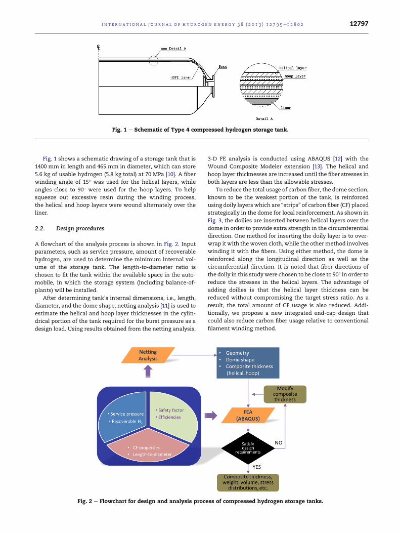
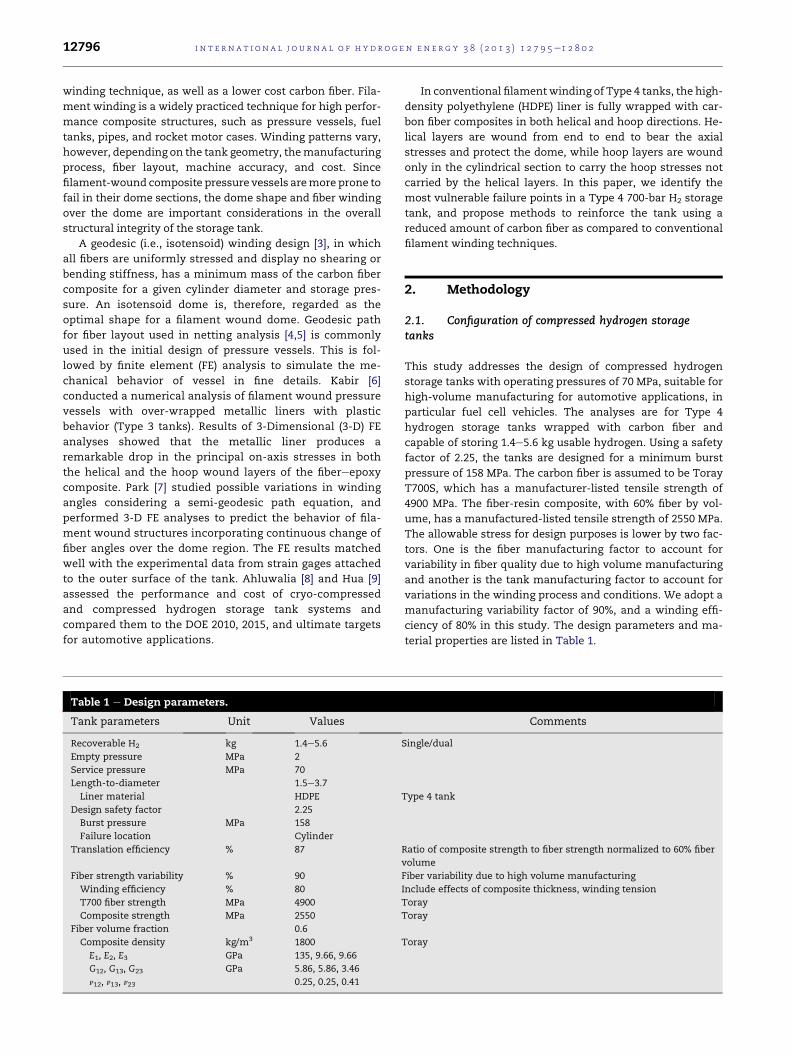
Fig. 1 e Schematic of Type 4 compressed hydrogen storage tank.
i n t e r n a t i o n a l j o u r n a l o f h y d r o g e n en e r g y 3 8 ( 2 0 1 3 ) 1 2 7 9 5e1 2 8 0 2 12797
Fig. 1 shows a schematic drawing of a storage tank that is
1400 mm in length and 465 mm in diameter, which can store
5.6 kg of usable hydrogen (5.8 kg total) at 70 MPa [10]. A fiber
winding angle of 15� was used for the helical layers, while
angles close to 90� were used for the hoop layers. To help
squeeze out excessive resin during the winding process,
the helical and hoop layers were wound alternately over the
liner.
2.2. Design procedures
A flowchart of the analysis process is shown in Fig. 2. Input
parameters, such as service pressure, amount of recoverable
hydrogen, are used to determine the minimum internal vol-
ume of the storage tank. The length-to-diameter ratio is
chosen to fit the tank within the available space in the auto-
mobile, in which the storage system (including balance-of-
plants) will be installed.
After determining tank’s internal dimensions, i.e., length,
diameter, and the dome shape, netting analysis [11] is used to
estimate the helical and hoop layer thicknesses in the cylin-
drical portion of the tank required for the burst pressure as a
design load. Using results obtained from the netting analysis,
Fig. 2 e Flowchart for design and analysis proce
3-D FE analysis is conducted using ABAQUS [12] with the
Wound Composite Modeler extension [13]. The helical and
hoop layer thicknesses are increased until the fiber stresses in
both layers are less than the allowable stresses.
To reduce the total usage of carbon fiber, the dome section,
known to be the weakest portion of the tank, is reinforced
using doily layers which are “strips” of carbon fiber (CF) placed
strategically in the dome for local reinforcement. As shown in
Fig. 3, the doilies are inserted between helical layers over the
dome in order to provide extra strength in the circumferential
direction. One method for inserting the doily layer is to over-
wrap it with the woven cloth, while the othermethod involves
winding it with the fibers. Using either method, the dome is
reinforced along the longitudinal direction as well as the
circumferential direction. It is noted that fiber directions of
the doily in this studywere chosen to be close to 90� in order to
reduce the stresses in the helical layers. The advantage of
adding doilies is that the helical layer thickness can be
reduced without compromising the target stress ratio. As a
result, the total amount of CF usage is also reduced. Addi-
tionally, we propose a new integrated end-cap design that
could also reduce carbon fiber usage relative to conventional
filament winding method.
ss of compressed hydrogen storage tanks.

Fig. 3 e Doilies for local reinforcement of the dome.
i n t e rn a t i o n a l j o u r n a l o f h y d r o g e n en e r g y 3 8 ( 2 0 1 3 ) 1 2 7 9 5e1 2 8 0 212798
3. Mathematical and numerical analysis
3.1. Netting analysis
Netting analysis is a preliminary sizing step to estimate the
thicknesses of the helical and hoop layers for given pressure
load, safety factor, and composite strength. To simplify this
procedure, it is assumed that the resin does not contribute to
carrying any part of the load. For a cylinder with a unit length
subjected to an inner pressure p (see Fig. 4 for an explanation
of the various parameters), force equilibrium along axial and
hoop directions gives,
axial : sf ;atacos2að2pRÞ ¼ p
�pR2
�(1)
hoop : sf ;atasin2aþ sf ;90t90 ¼ pR (2)
From Eqs. (1) and (2), the thicknesses of the helical layers
and the hoop layers can be obtained as
ta ¼ pR=�2sf ;acos
2a�
(3)
t90 ¼ pR�2� tan2a
���2sf ;90
�(4)
where R is the tank radius, sf,a and sf,90 are design allowable
stress of fiber in the helical layer and the hoop layer,
respectively.
Fig. 4 e Circular cylindrical storage tank: left, cylinder su
3.2. FE modeling
FE analyses were performed using ABAQUS 6.11 with the
Wound Composite Modeler extension. The geometry of the
tank determined in the previous section was used to create
the FE model. First, the FE model was set up with only helical
and hoop windings, i.e., without any special extra dome
reinforcement, considered as a base case. The results of this
analysis were subsequently compared with the results of a
model that incorporates doilies for dome reinforcement.
When doilies are used in themodel, they are inserted between
the helical layers. In view of the symmetry, axial symmetric
boundary conditions were applied at the mid-plane cross
section of the cylinder through the Z-plane, and cyclic
boundary conditionswere assigned in the q-direction on the 5�
azimuthal strip. The opening end of the tank was allowed to
translate along the Z-direction. Material properties such as
tensile strength, Young’smodulus, Poisson’s ratio are listed in
Table 1.
The helical layer thickness and winding angle were varied
element by element in the dome section. The FE model was
created using 3-D elements provided in ABAQUS. To ensure
convergence, four elements in the azimuthal circumferential
direction and 10 to 16 elements through the cylinder thickness
direction were used.
3.3. Wound Composite Modeler
The Wound Composite Modeler extension was used to auto-
matically generate FE models of filament wound pressure
vessels. The Wound Composite Modeler requires geometric
parameters, such as type of dome, cylinder diameter, and
winding layout of helical and hoop windings, to define the
geometry of the tank in the cylindrical and dome portions. The
Wound Composite Modeler also calculates the change of fiber
angles over the dome (Fig. 5) and applies it to the FE model.
3.4. Results and discussions
FE analyses were performed on filament wound storage tanks
with and without special dome reinforcement techniques,
which include the use of doilies or an integrated end-cap. In
this paper, the FE models for the various cases are identified
from themodel name. For example, V145-DY-30modelmeans
that it has the inner volume of 145 L, the dome is reinforced by
doily layers, and the last two digits,�30 indicates the length to
bject to inner pressure P; right, helical fiber element.

Fig. 5 e Variation of helical angle in the dome section.
0 200 400 600 800
0
1
2
helical layer
90o hoop winding Variable hoop winding
Stre
ss a
long
fibe
r dire
cito
n, G
Pa
Distance, mm
hoop layer
CL
Fig. 6 e Fiber stress distribution in helical and hoop layers
of 145L model with different hoop winding patterns.
i n t e r n a t i o n a l j o u r n a l o f h y d r o g e n en e r g y 3 8 ( 2 0 1 3 ) 1 2 7 9 5e1 2 8 0 2 12799
diameter ratio times ten of the hydrogen storage tank model.
Other notations include ND (no doilies) and EC (end cap).
Table 2 summarizes the results for various models that are
discussed in this section.
3.4.1. Hoop winding angleThe case V145-ND-30a represents a base case with only he-
lical and hoop windings for a tank that holds 5.6 kg usable
hydrogen. The helical and hoop thicknesses are 18.5 mm and
19.6 mm, respectively. The total composite weight of the
tank is 107.4 kg. Fig. 6 shows the upper/lower bound stress
profiles at the helical and hoop layers determined by FE
analysis. In this baseline design where the hoop angle is 90�,the stress decreases from inner to outer layers, and the
stress at the innermost layer is 33% higher than that in the
outermost layer. Our analysis showed that the stress distri-
bution could be made more uniform across the layers by
varying the fiber angle from 75� at the innermost layer,
increasing to 90� at the outermost layer. The more uniform
stress distribution in case V145-ND-30b results in smaller
hoop layer thicknesses of 17.6 mm. The amount of CF usage
is reduced to 102 kg.
Table 2 e Geometry and weight of the composite for different
FE model H2, kg L/D ID, mm
Helical
V36-DY-30 1.4 3.0 246 9.0
V52-DY-25 2.0 2.5 300 11.0
V73-DY-30 2.8 3.0 310 11.3
V104-DY-16 4.0 1.6 378 15.5
V145-ND-15 5.6 1.5 521 22.4
V145-DY-15 5.6 1.5 521 17.8
V145-ND-30a 5.6 3.0 391 18.5
V145-ND-30b 5.6 3.0 391 18.5
V145-DY-30 5.6 3.0 391 14.3
V145-EC-30 5.6 3.0 391 14.3
3.4.2. L/D ratioTanks that fit within the available space onboard a vehicle
typically have length-to-diameter ratio between w1.5 and
w4.0. For the same volume of 145 L, analysis was carried out
for a tank with a smaller L/D ratio of 1.5 and compared with
case V145-ND-30b described above. The results of the analysis
showed only a small difference in the amount of composite
needed, 103.6 kg for L/D of 1.5 versus 102.0 kg for L/D of 3.0.
3.4.3. Doilies for reinforcing the dome regionsTo reinforce a pressure vessel for aerospace applications, the
use of doilies has been suggested by Dorsch [14]. James [15]
reported that the use of wafer reinforcement increased the
calculated burst pressure by 17% compared to a model
without the reinforcement. However, since the winding angle
decreases rapidly with increasing radial distance from the
boss, the wafer’s outer edge fibers approach perpendicularity
to the polar fibers, resulting in a severe stiffness discontinuity.
This high angular orientation between wafer and polar fibers
also causes strain incompatibilities, which may lead to
delamination and premature vessel failure.
models.
Thickness, mm CF composite weight, kg
Hoop Doily End-cap
11.1 4.5 No 23.1
13.3 5.0 No 33.3
14.0 5.5 No 46.0
20.0 6.0 No 68.0
23.5 e No 103.6
23.5 6.5 No 93.1
19.6 e No 107.4
17.6 e No 102.0
17.6 5.5 No 91.0
17.6 e 5.0 92.6
0
30
60
90
120
w/o Doilyw/ Doily
93.1 91.0
3.0
102.0
Wei
ght o
f CF
Com
posi
te, k
g
L/D Ratio
103.6
1.5
Fig. 8 e Comparison of composite usage for models with or
i n t e rn a t i o n a l j o u r n a l o f h y d r o g e n en e r g y 3 8 ( 2 0 1 3 ) 1 2 7 9 5e1 2 8 0 212800
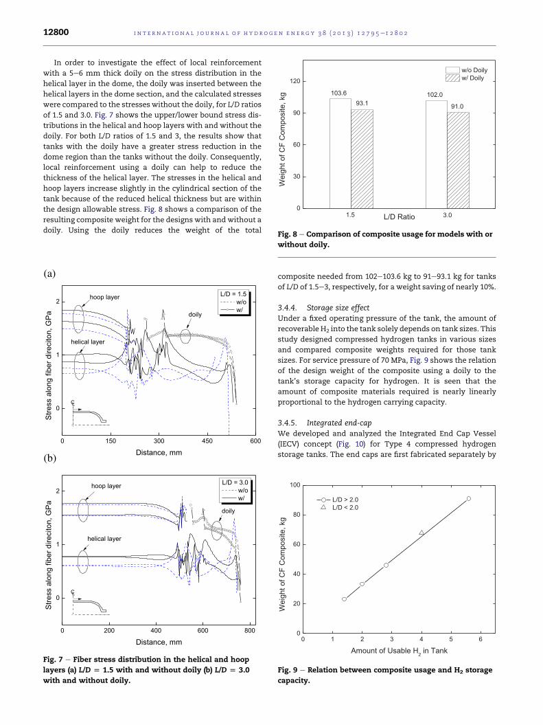
In order to investigate the effect of local reinforcement
with a 5e6 mm thick doily on the stress distribution in the
helical layer in the dome, the doily was inserted between the
helical layers in the dome section, and the calculated stresses
were compared to the stresses without the doily, for L/D ratios
of 1.5 and 3.0. Fig. 7 shows the upper/lower bound stress dis-
tributions in the helical and hoop layers with and without the
doily. For both L/D ratios of 1.5 and 3, the results show that
tanks with the doily have a greater stress reduction in the
dome region than the tanks without the doily. Consequently,
local reinforcement using a doily can help to reduce the
thickness of the helical layer. The stresses in the helical and
hoop layers increase slightly in the cylindrical section of the
tank because of the reduced helical thickness but are within
the design allowable stress. Fig. 8 shows a comparison of the
resulting composite weight for the designs with andwithout a
doily. Using the doily reduces the weight of the total
(a)
(b)
0 150 300 450 600
0
1
2
doily
helical layer
L/D = 1.5 w/o w/
Stre
ss a
long
fibe
r dire
cito
n, G
Pa
Distance, mm
hoop layer
CL
0 200 400 600 800
0
1
2
doily
helical layer
L/D = 3.0 w/o w/
Stre
ss a
long
fibe
r dire
cito
n, G
Pa
Distance, mm
hoop layer
CL
Fig. 7 e Fiber stress distribution in the helical and hoop
layers (a) L/D [ 1.5 with and without doily (b) L/D [ 3.0
with and without doily.
without doily.
composite needed from 102e103.6 kg to 91e93.1 kg for tanks
of L/D of 1.5e3, respectively, for a weight saving of nearly 10%.
3.4.4. Storage size effectUnder a fixed operating pressure of the tank, the amount of
recoverable H2 into the tank solely depends on tank sizes. This
study designed compressed hydrogen tanks in various sizes
and compared composite weights required for those tank
sizes. For service pressure of 70 MPa, Fig. 9 shows the relation
of the design weight of the composite using a doily to the
tank’s storage capacity for hydrogen. It is seen that the
amount of composite materials required is nearly linearly
proportional to the hydrogen carrying capacity.
3.4.5. Integrated end-capWe developed and analyzed the Integrated End Cap Vessel
(IECV) concept (Fig. 10) for Type 4 compressed hydrogen
storage tanks. The end caps are first fabricated separately by
0 1 2 3 4 5 60
20
40
60
80
100
L/D > 2.0 L/D < 2.0
Wei
ght o
f CF
Com
posi
te, k
g
Amount of Usable H2 in Tank
Fig. 9 e Relation between composite usage and H2 storage
capacity.

Fig. 10 e Integrated end-cap for local reinforcement of the
dome.
(a)
(b)
0 150 300 450 600 750
0
1
2
Hoop layer upper bound lower boundHelical layer upper bound lower boundEnd-cap
Stre
ss a
long
fibe
r dire
cito
n, G
Pa
Distance, mm
End Cap : 30 deg fiber angles
CL
0 150 300 450 600 750
0
1
2
Hoop layer upper bound lower boundHelical layer upper bound lower boundEnd-cap
End Cap : 60 deg fiber angles
Stre
ss a
long
fibe
r dire
cito
n, G
Pa
Distance, mm
CL
Fig. 11 e Fiber stress distribution in helical and hoop
layers: (a) with end-cap using 30� fiber angle, (b) with end-
cap using 60� fiber angle.
i n t e r n a t i o n a l j o u r n a l o f h y d r o g e n en e r g y 3 8 ( 2 0 1 3 ) 1 2 7 9 5e1 2 8 0 2 12801
Resin Transfer Molding (RTM) and are made of the same car-
bon fiber (T700S) and resin material that is used in the tank
overwrap. The tensile strength of end cap is assumed to be
75% of the fiber strength used in helical and hoop layers. The
end caps are then integrated with the HDPE liner and the
aluminum boss using the blow molding method. Finally, the
tank is reinforced by conventional helical and hoopwinding of
the fibers. In this design, the inner pressure is carried by the
end cap as well as the helical layer in the dome, so that the
amount of helical windings needed is less than that in a
conventional tank that is reinforced by filament wound fibers
only. Fig. 10 shows a sectional view of a 5-mm-thick end-cap.
To investigate the effect of fiber angles in the end-cap on fiber
stresses in the helical and hoop layers, end capswith�30� and�60� fiber angles were modeled.
Fig. 11 plots the stresses along the fiber direction in helical
and hoop layer of V145-ECwith end-cap of�30� and�60� fiberangle. Our FE analysis shows that the stress in the composite
is reduced at the shoulder as well as near the boss flange. The
peak stress is moved from the dome section (in filament
wound tank) to the cylindrical section of the tank. For the end-
caps with �30� fiber angles, it is seen that stresses in hoop
layer tend to increase around the junction of the cylinder and
the dome. This happens because the end-caps with �30� fiberangles do not have enough stiffness to resist the deformation
in radial direction. With end-cap of �60� fiber angle, however,
stresses in the hoop layers around the junction are seen to
decrease, while reducing stresses in the helical layers at the
dome. In addition, it is seen that the fiber stresses in the end-
cap region are evenly distributed. Fig. 12 shows the shear
stresses at the layer interface for the end-cap with �60� fiber
angles (V145-EC-30). The shear stresses are well distributed
over the dome ranging from30 to 80MPa. Similar to the tensile
stress distribution across the layers, the shear stress is highest
at the innermost interface between the end-cap and the first
helical layer, and decreases at the outer layer interfaces. The
weight of the composite with the end-cap was 92.6 kg, which
is a little heavier than the model with the doily, 91 kg, partly
due to the lower tensile strength assumed for the end-caps.
0 100 200 300 400 500 600 700 800-400
-300
-200
-100
0
100
200
dome
Interface 1st 2nd 3rd
Shea
r stre
ss, M
Pa
Distance, mm
cylinder
Fig. 12 e Shear stresses distribution at fiber layer interfaces
with end-cap using ±60� fiber angles.

i n t e rn a t i o n a l j o u r n a l o f h y d r o g e n en e r g y 3 8 ( 2 0 1 3 ) 1 2 7 9 5e1 2 8 0 212802
4. Conclusions
This study dealt with the design and analysis of Type 4 fila-
ment wound compressed hydrogen storage tanks for fuel cell
vehicles. The focus of the analysis was on only the carbon
fibereepoxy composite used in overwrap windings to provide
the structural strength for the compressed gas tankeHDPE
liner, outer protection, if any, boss, or other balance-of-plant
in the total hydrogen storage system were not included in
the analyses discussed in this paper. The configuration of the
composite was determined for various tank volumes and
thicknesses of helical and hoop layers were calculated using
netting analysis for preliminary sizing. The effects of three
main parameters on the stress distributions in the composite
were analyzed: (1) the hoop winding angle, (2) use of a rein-
forcing doily in the dome region, and (3) use of an integrated
end-cap. The main findings are summarized below.
� Changing the hoopwinding angle in the various hoop layers
led to w5% reduction of the composite needed to meet the
same design requirements.
� In the investigation of the effect of tank L/D ratio on com-
posite weight for 5.6 kg recoverable H2 storage capacity
tanks, the results of the analysis for L/D of 1.5 and 3.0
showed only a small difference in the amount of composite
needed, 103.6 kg versus 102.0 kg, respectively.
� Usingadoily inthedomesectionreduced thestressesnear the
opening end of the tank, but the doily did not help to reduce
the stresses over the shoulder section which was not rein-
forced by the doily. Also, using the doily reduces theweight of
the total composite needed from 102e103.6 kg to 91e93.1 kg.
� The composite weight needed for satisfying design re-
quirements increases linearlywith the capacity of storedH2.
� In the IECV design, the stress in the dome is reduced sub-
stantially and is lower than the stress in the cylindrical
section. It was shown that using the end-cap could reduce
the required thickness of helical layer and result in com-
posite weight-saving by about 10%.
Acknowledgments
This work was supported by the U.S. Department of Energy’s
Office of Energy Efficiency and Renewable Energy. Ms. Grace
Ordaz of the Office of Fuel Cell Technologies was the Tech-
nology Development Manager for this study. Argonne Na-
tional Laboratory, a U.S. Department of Energy Office of
Science laboratory, is operated by UChicago Argonne, LLC,
under Contract No. DE-AC02-06CH11357.
r e f e r e n c e s
[1] Wipke K, Sprik S, Kurtz J, Ramsden T, Ainscough C, Saur G.National fuel cell electric vehicle learning demonstration.Final Report. Golden (CO): National Renewable EnergyLaboratory; 2012 July. Report No.: NREL/TP-5600e54860.Contract No.: DE-AC36-08GO28308. Sponsored by theDepartment of Energy.
[2] Hua TQ, Ahluwalia RK, Peng JK, Kromer M, Lasher S,Mckenney K, et al. Technical assessment of compressedhydrogen storage tank systems for automotive applications.Argonne (IL): Argonne National Laboratory,Nuclear Engineering Division; 2010 September. Report No.:ANL-10/24.
[3] Zickel J. Isotensoid pressure vessels. ARS J 1962;32:950e1.[4] Rosato DV, Grove CS. Filament winding: its development,
manufacture, applications, and design. New York:Interscience; 1964.
[5] Peter ST, Humphrey WD, Foral RF. Filament winding:composite structure fabrication. California: SAMPE; 1991.
[6] Kabir MZ. FE analysis of composite pressure vessels with aload sharing metallic liner. Compos Struct 2000;49:247e55.
[7] Park J, Hong C, Kim C. Analysis of filament wound compositestructures considering the change of winding angles throughthe thickness direction. Compos Struct 2002;55:63e71.
[8] Ahluwalia RK, Hua TQ, Peng JK. Technical assessment ofcryo-compressed hydrogen storage tank systems forautomotive applications. Int J Hydrogen Energy2010;35:4171e84.
[9] Hua TQ, Ahluwalia RK, Peng JK, Kromer M, Lasher S,Mckenney K, et al. Technical assessment of compressedhydrogen storage tank systems for automotive applications.Int J Hydrogen Energy 2011;36:3037e49.
[10] SAE TIR J2579Technical information report for fuel systemsin fuel cell and other hydrogen vehicles. USA: Society ofAutomotive Engineers; 2008.
[11] Roylance DK. Netting analysis for filament-wound pressurevessels. Watertown (MA): Army Materials and MechanicsResearch Center, Composites Division; 1976 August. ReportNo.: AMMRC TN 76e3.
[12] Simulia Inc. ABAQUS analysis user’s manual; 2011.[13] Simulia Inc.. Wound Composite Modeler for ABAQUS user;
2011.[14] Dorsch RE, inventor; Uniroyal Inc., assignee. Doily for
reinforcing the wall of a flexible walled liquid container,United States patent US 3847716; 1973 February 28.
[15] James DE, James AY. Graphite epoxy pressure vessel domereinforcement study. In: Proceedings of the 32nd int SAMPEsymposium 1987.