1 science park 904, 1098xh amsterdam, the netherlands
TRANSCRIPT

Continuous Bose-Einstein condensation
Chun-Chia Chen (陳俊嘉) ID ,1 Rodrigo Gonzalez Escudero ID ,1 Jirı Minar ID ,2, 3
Benjamin Pasquiou ID ,1, 3 Shayne Bennetts ID ,1, 3 and Florian Schreck ID 1, 3, ∗
1Van der Waals-Zeeman Institute, Institute of Physics, University of Amsterdam,Science Park 904, 1098XH Amsterdam, The Netherlands
2Institute for Theoretical Physics, Institute of Physics, University of Amsterdam,Science Park 904, 1098XH Amsterdam, The Netherlands
3QuSoft, Science Park 123, 1098XG Amsterdam, The Netherlands(Dated: September 17, 2021)
Bose-Einstein condensates (BECs) are macroscopic coherent matter waves that have revolution-ized quantum science and atomic physics. They are essential to quantum simulation [1] and sens-ing [2, 3], for example underlying atom interferometers in space [4] and ambitious tests of Einstein’sequivalence principle [5, 6]. The key to dramatically increasing the bandwidth and precision ofsuch matter-wave sensors lies in sustaining a coherent matter wave indefinitely. Here we demon-strate continuous Bose-Einstein condensation by creating a continuous-wave (CW) condensate ofstrontium atoms that lasts indefinitely. The coherent matter wave is sustained by amplificationthrough Bose-stimulated gain of atoms from a thermal bath. By steadily replenishing this bathwhile achieving 1000x higher phase-space densities than previous works [7, 8], we maintain the con-ditions for condensation. This advance overcomes a fundamental limitation of all atomic quantumgas experiments to date: the need to execute several cooling stages time-sequentially. Continuousmatter-wave amplification will make possible CW atom lasers, atomic counterparts of CW opticallasers that have become ubiquitous in technology and society. The coherence of such atom laserswill no longer be fundamentally limited by the atom number in a BEC and can ultimately reachthe standard quantum limit [9–11]. Our development provides a new, hitherto missing piece ofatom optics, enabling the construction of continuous coherent matter-wave devices. From infra-sound gravitational wave detectors [12, 13] to optical clocks [14, 15], the dramatic improvement incoherence, bandwidth and precision now within reach will be decisive in the creation of a new classof quantum sensors.
Interferometers listen to gravitational waves, imagethe shadow of black holes, and are at the core of count-less other high-precision measurements in science andtechnology. An interferometer achieves its outstandingsensitivity through the interference of waves. For ex-ample, the wave-like properties of matter are exploitedin the world’s most accurate sensors of acceleration andgravity [16]. Interferometers reach optimal sensitivityand bandwidth by using continuous, coherent, high-brightness sources, which is why many optical interfer-ometers, such as LIGO, are based on CW lasers. How-ever, no continuous matter-wave source with long-rangecoherence currently exists, which prevents atom interfer-ometers from reaching their full potential. Creating sucha CW source of matter will benefit applications rangingfrom geodesy [17, 18], to tests of Einstein’s equivalenceprinciple [5, 6], gravitational-wave detection [12, 13, 19–21], and dark-matter and dark-energy searches [22, 23].
The key to realizing a CW BEC of atoms is to contin-uously amplify the atomic matter wave while preservingits phase coherence [24]. An amplification process is es-sential to compensate naturally occurring atom losses,e.g. from molecule formation. It is also needed to re-place the atoms that will be coupled out of the BEC forsustaining an atom laser or atom interferometer. Ad-dressing this challenge requires two ingredients: a gain
mechanism that amplifies the BEC and a continuous sup-ply of ultracold atoms near quantum degeneracy.
The first steps towards a continuous gain mechanismwere taken by [25], where merging of independent con-densates periodically added atoms to an already exist-ing BEC, but where coherence was not retained acrossmerger events. A Bose-stimulated gain mechanism intoa single dominant mode (the BEC) is required to pro-vide gain without sacrificing phase coherence. Such gainmechanisms have been demonstrated using elastic colli-sions between thermal atoms [24, 26], stimulated photonemission [27], four wave mixing [28, 29] or superradi-ance [30]. However, in all these demonstrations the gainmechanism could not be sustained indefinitely.
To sustain gain the second ingredient is needed: a con-tinuous supply of ultracold, dense gas with a phase-spacedensity — the occupancy of the lowest motional quan-tum state — approaching ρ = 1. Great efforts were spentdeveloping continuously cooled beams of atoms [31, 32]and continuously loaded traps [7, 8], which so far havereached phase-space densities of ρ = 10−3. To achievethe required µK temperatures, these experiments haveto use laser cooling, but near-resonant laser cooling lightis highly destructive for BECs [33]. Several experimentshave maintained a BEC in the presence of harmful light,either by spatially separating the laser cooling from thequantum gas [7, 25, 31, 32, 34] or by reducing the quan-tum gas’ absorbance [24, 35–37].
Here we demonstrate the creation of a CW BEC that
arX
iv:2
012.
0760
5v2
[co
nd-m
at.q
uant
-gas
] 1
6 Se
p 20
21

2
Steady-statenarrow-line MOT
Laser coolingin x and yAtomic beam
in dipole guide
Zeeman slower
Reservoir + dimple+ transparency beam
BEC
xy
z
g
a
b
c
“Transparency”3P1
Cooling light 1S0
3S1
λ: 689 nmГ/2: 7.5 kHz
λ: 688 nmГ/2: 3.8 MHz
Δ
Electronic levels
Ener
gy Light shift by transparency beam
Dimple + transparency
Reservoir
z
3P1
1S0
Potential landscape
Laser cooling
Spontaneous emission
Vibrational levels
3-body loss
Elasticcollisions
Bose-enhancedstimulated scattering
Atom influx
BEC
18 ms time of flight
1 mm
y
z 0
0.5
Opt
ical
den
sity
Fig. 1. |Experimental setup and scheme. a, 84Sr atoms from a steady-state narrow-line magneto-optical trap (MOT)are continuously outcoupled into a guide and loaded into a crossed-beam dipole trap that forms a large reservoir with asmall, deep dimple. Atoms accumulate in the laser cooled reservoir and densely populate the dimple, where a Bose-Einsteincondensate (BEC) forms in steady state. After time-of-flight expansion, the BEC shows as an elliptical feature in the center ofan absorption image. b, By off-resonantly addressing the 3P1− 3S1 transition using a “transparency” laser beam, we producea strong spatially varying light shift on the 3P1 electronic state, rendering atoms locally transparent to laser cooling photonsaddressing the 1S0 − 3P1 transition. This enables condensation in the protected dimple region. c, Schematic of the potentiallandscape from both reservoir and dimple trap, and of the dominant mechanisms leading to BEC atom gain and loss.
can last indefinitely. Our experiment comprises both in-gredients, gain and continuous supply, as illustrated inFig. 1. The centerpiece of the experiment consists ofa large “reservoir” that is continuously loaded with Sratoms and that contains a small and deep “dimple” trapin which the BEC is created. The gas in the reservoir iscontinuously laser-cooled, and exchanges atoms and heatwith the dimple gas. A “transparency” beam rendersatoms in the dimple transparent to harmful laser-coolingphotons. The dimple increases the gas density while thetemperature is kept low by thermal contact with thereservoir. This enhances the phase-space density, leadingto the formation of a BEC. Bose-stimulated elastic col-lisions continuously scatter atoms into the BEC mode,providing the gain necessary to sustain it indefinitely.
Experiment
In order to continuously refill the reservoir, a streamof atoms from an 850 K-hot oven flows through a seriesof spatially-separated laser cooling stages. The initialstages load a steady-state magneto-optical trap (MOT)operated on the 7.5 kHz-narrow 1S0− 3P1 transition [7],shown in Fig. 1a. An atomic beam of µK-cold atomsis then outcoupled and guided [32] 37 mm to the reser-voir. This long-distance transfer prevents heating of theatoms in the reservoir by laser cooling light used in ear-lier cooling stages.
To slow the ∼ 10-cm s−1 atomic beam and load it intothe reservoir while minimizing resonant light, we imple-ment a Zeeman slower on the 1S0− 3P1 |m′J = −1〉 tran-
sition. This slower employs a single, counterpropagatinglaser beam together with the 0.23 G cm−1 MOT mag-netic field gradient along the guide [38]. The 11.5 µK-deep reservoir is produced by a horizontal 1070-nmlaser beam focused to an elliptical spot with waistswy = 14.5 µm vertically and wx = 110 µm horizon-tally. A 6° horizontal angle between the guide andreservoir allows the decelerated atoms to be nudgedinto the reservoir after reaching the intersection. Theatomic beam and the reservoir are radially cooled bytwo pairs of beams addressing the magnetically insensi-tive 1S0|mJ = 0〉 − 3P1|m′J = 0〉 transition.
This arrangement of traps and cooling beams leadsto the irreversible loading of the reservoir with a fluxΦR = 1.4(2) × 106 atoms s−1 [38], a radial tempera-ture of TRr = 0.85(7) µK, and an axial temperature ofTRz = 3.0(5) µK. The corresponding phase-space flux is
κ =(∂ρR∂t
)T
= ΦR
(~3ωRxωRyωRzk3BT
2RrTRz
)= 5.0(2) × 10−2 s−1
[39], where ~ is the reduced Planck constant, kB theBoltzmann constant, and ωRi/2π are the reservoir trapfrequencies.
To reduce heating and loss we use a “transparency”laser beam [36] that renders atoms in the dimple traptransparent to near-resonant cooling light. This beamis overlapped with the dimple and its frequency is set33 GHz blue detuned from the 3P1 − 3S1 transition, soas to locally apply a differential light shift on the 1S0 −3P1 transition, see Fig. 1b and [38]. All transitions to the3P1 manifold are thereby shifted by more than 500 times

3
0
0.5
Opt
ical
den
sity
a thold = 2.2 s
y
z 1 mm
b thold = 3.2 s
y
z
∆O
D
-0.07
0.07Thermal only tBi-modal t (thermal part)Bi-modal t (BEC part)
Position (mm) Position (mm)
c d
1.9 2 2.1 2.2 2.3 2.4 2.50.2
0.3
0.4
0.5
1.9 2 2.1 2.2 2.3 2.4 2.5
feO
ptic
al d
ensi
ty
Fig. 2. |Detection of the CW BEC. a, b, Absorption images of the atomic cloud before and after condensation. The atomsare imaged after an 18 ms time-of-flight expansion. c, d, Optical density within the rectangles marked by corners in a and b,averaged along y. Fitted profiles using a thermal-only distribution (green dashed line) or a bi-modal distribution, consisting ofa thermal (red line) and a Thomas-Fermi (blue line) component. The thermal-only fit fails to represent the condensed atomsin d (blue shaded area). e, f, Corner-marked square region of absorption images a and b minus thermal parts of the bi-modalfits, showing the continuous-wave BEC.
the 1S0 − 3P1 linewidth, while atoms in the 1S0 groundstate experience a light shift of only 20 kHz. Withoutthe transparency beam, the lifetime of a pure BEC in thedimple is shorter than 40 ms while with the transparencybeam it exceeds 1.5 s [38].
For a BEC to form in the dimple, the ultracold gasmust exceed a critical phase-space density of order one.The dimple is produced by a vertically propagating1070-nm beam with 27 µm waist focused at the cen-ter of the reservoir. In steady state the 6.9(4) × 105
atoms in the dimple are maintained at a low tempera-ture (TD = 1.08(3) µK) by thermalization through col-lisions with the 7.3(1.8)× 105 laser-cooled atoms in thereservoir [36]. The dimple provides a local density boost,thanks to its increased depth (7 µK) and small volumecompared to the reservoir [40–42]. This leads to a suffi-cient phase-space density for condensation.
In a typical instance of our experiment we suddenlyswitch all laser beams on and let atoms accumulate inthe reservoir and dimple for a time thold. The phase-space density in the dimple increases and eventually aBEC forms. The BEC grows thanks to preferential Bose-stimulated scattering of non-condensed atoms into themacroscopically populated BEC mode. This producescontinuous matter-wave amplification, the gain mecha-nism for the CW BEC [26]. The BEC grows until losseseventually balance gain and steady state is reached.
Analysis of the CW BEC
We now demonstrate the existence of a BEC and latershow that it persists indefinitely. To tackle the first pointwe analyze atomic cloud density images for thold = 2.2 sand 3.2 s, immediately before and after the formationof a BEC, as shown in Fig. 2a, b. These x-integrated
absorption images are taken after switching off all laserbeams and letting the cloud expand for 18 ms. Both im-ages show broad distributions of thermal atoms that arehorizontally extended, reflecting the spatial distributionof the gas before expansion. Interestingly, the imagefor the longer thold shows a small additional ellipticalfeature at the location of highest optical density, whichis consistent with the presence of a BEC. The appear-ance of a BEC is clearly revealed in Fig. 2c, d, showingy-integrated density distributions. For short thold onlya broad, thermal distribution exists. However for longthold a bi-modal distribution appears, the hallmark of aBEC.
We further validate the BEC’s existence by fitting the-oretical distributions to the absorption images in Fig. 2a,b. As shown in Fig. 2c, d, excellent agreement is foundby combining a thermal distribution with a Thomas-Fermi (TF) distribution describing the BEC. At shorthold times, we find that a thermal fit alone is sufficientto describe the data, whereas at longer times the ad-ditional TF component is required, indicating the pres-ence of a BEC. To clearly visualize the BEC, we removethe thermal fit component from the data, see Fig. 2e,f. The pronounced anisotropic shape of the BEC inFig. 2f is consistent with the expansion of a BEC fromthe anisotropic dimple, whose trap frequency along they axis is approximately double that along z [38].
Once established, the BEC can be maintained insteady state indefinitely with gain balancing losses. Asshown in Fig. 3, we study the formation transient andstability of the condensate by recording and analyzingimages for different thold. Fig. 3a shows representativedensity profiles during the initial 5 s formation transient

4
BEC detection limit BEC detection limit
Phase-space density TheoryBEC atom number
A B C D E FG H I J
Opt
ical
den
sity
Position (mm)
Histogram of 208 runsfor t hold = 15 s
a
b cA - F G H I J
0 10 20 300.0
0.5
1.0
1.5 N = 7400
σ N = 2300
Time t hold (s)
Time t hold (s)
0.1
0.2
0.3
0.4
0.5
22.2
2.4
1 3 5 7 9 11 13 150.0
0.5
1.0
1.5
BEC
ato
m n
umbe
r (1
0) 4
20 40 600
1
2
3
4
Phas
e-sp
ace
dens
ity
Counts
BEC
ato
m n
umbe
r (1
0) 4
Fig. 3. |Formation and stability of the CW BEC. a, Profiles as in Fig. 2c,d for various hold times (marked in b)first during the formation of the BEC (A: 1.5 s, B: 1.8 s, C: 2.2 s, D: 2.5 s, E: 2.8 s, F: 3.2 s), then during the steady stateof the continuous-wave BEC (G: 15 s, H: 30 s, I: 45 s, J: 60 s). b, Evolution of the BEC atom number and the dimple atomphase-space density ρD in dependence of hold time thold after suddenly switching all laser beams on. The dashed blue lineshows the result of the BEC evolution fitted to the data before 15 s using the rate-equation model [38]. The error bars showthe standard deviation from binning ∼ 4 measurements for each time. c, Histogram of the BEC atom number from 208 imagesfor thold = 15 s, long after the establishment of steady state (blue star in b). No points fall below our BEC detection limit of2000 atoms. The 95 % confidence interval (4σN) calculated from this data set is given in b at 15 s (blue rectangle).
(A-F) and then in the presence of a stable BEC (G-J).Likewise, Fig. 3b shows the evolution and then stabilityof the BEC atom number and the peak phase-space den-
sity in the dimple ρD = ND
(~3ωDxωDyωDz
k3BT3D
), where ND
is the thermal atom number in the dimple and ωDi/2πare the dimple trap frequencies. The steady-state BECis observed over times much longer than both the life-time of a pure BEC (1.5 − 3 s) and the background-gaslimited lifetime (7 s) [38].
Although we do not continuously monitor thecontinuous-wave BEC, its atom number fluctuations canbe estimated from many independent observations. Tostudy these fluctuations we collected ∼ 200 measure-ments for thold = 15 s, significantly longer than both thelifetimes in the system and the formation transient, seeFig. 3c. A BEC atom number of N = 7400(2300) is ob-served, with none of the points falling below our BECdetection threshold of 2000 atoms [38].
Modelling the formation, growth and stabilization ofthe BEC provides valuable insights into this new driven-dissipative system. It also provides the gain and loss
from the BEC, which are important for practical ap-plications such as producing a continuous-wave atomlaser [27] and improving matter-wave coherence. We ex-plain the BEC dynamics by fitting a phenomenologicalrate-equation model to measured temperature and atomnumbers. Our analysis covers the condensate formationand perturbations such as disrupting the reservoir load-ing [38]. From this model we estimate a steady-stategain of 2.4(5)× 105 atoms s−1 into the BEC, with repre-sentative fits shown in Fig. 3b and Fig. S7. A substantialfraction of this gain could conceivably be translated intoan outcoupled flux forming a CW atom laser. We alsofind that losses in the BEC at steady state are dominatedby three-body recombinations with thermal atoms, dueto the gas density exceeding 5 × 10¹⁴ atoms cm−3. Thepresence of high, steady in-flux and loss makes our BECa driven-dissipative system. We confirm this by show-ing that it is impossible to model the atoms in the trapas a closed system in thermal equilibrium [38]. Opendriven-dissipative systems like this one are thought toexhibit rich nonequilibrium many-body physics waitingto be explored, such as purity oscillations [43], behaviors

5
described by new critical exponents [44], and unusualquantum phases, especially in lower dimensions [45].
Discussion and conclusion
In summary, we have demonstrated continuous Bose-Einstein condensation. The resulting CW BEC can besustained indefinitely using constant gain provided by acombination of Bose-stimulated scattering and atom re-filling with high phase-space flux. Our work paves theway for continuous matter-wave devices, where matter-wave coherence is no longer limited by the atom numberand lifetime of a single condensate [10]. In the near fu-ture, BEC purity and matter-wave coherence can be im-proved by enhancing the phase-space flux loading thedimple. A straight-forward option to achieve this isto render the reservoir laser cooling uniform by usinga magic-wavelength reservoir trap. Further options in-clude lowering the reservoir temperature by Raman cool-ing [37] or by adding a continuously operating evapora-tion stage [31]. Real-time non-destructive detection andfeedback [46] can be used to stabilize the CW BEC atomnumber to a stability approaching the shot-noise level[47] and even beyond, leading to squeezed states [48] formeasurements beyond the standard quantum limit [10].
Our CW BEC is the matter-wave equivalent of a CWoptical laser with fully reflective cavity mirrors. A tan-talizing prospect is to add an output coupler to extracta propagating matter-wave. This could be implementedby coherently transferring atoms to an untrapped stateand would bring the long-sought CW atom laser finallywithin reach [39, 49]. This prospect is especially com-pelling because our CW BEC is made of strontium, theelement used in some of today’s best clocks [50] and theelement of choice for future cutting-edge atom interfer-ometers [12, 13, 19–21, 51]. Our work will inspire a newclass of such quantum sensors.
Acknowledgments We thank Francesca Fama, SergeyPyatchenkov, Jens Samland, Sheng Zhou, and the work-shop of FNWI, especially Jan Kalwij, Tristan van Klin-geren, and Sven Koot, for technical assistance. Wethank Vincent Barbe, Corentin Coulais, Sebastian Diehl,Klaasjan van Druten, David Guery-Odelin, Wolf von Kl-itzing, Ben van Linden van den Heuvell, Robert Spreeuw,Josephine Tan, Premjith Thekkeppat, and Jook Wal-raven for comments on the manuscript. We thank theNWO for funding through Vici grant No. 680-47-619and the European Research Council (ERC) for fund-ing under Project No. 615117 QuantStro. This projecthas received funding from the European Union’s Horizon2020 research and innovation programme under grantagreement No 820404 (iqClock project). B.P. thanks theNWO for funding through Veni grant No. 680-47-438and C.-C.C. thanks support from the MOE Technolo-gies Incubation Scholarship from the Taiwan Ministry ofEducation.
Author contribution C.-C.C. and S.B. built the ap-paratus. C.-C.C., R.G.E., and S.B. performed the
investigation and data collection. C.-C.C., B.P. andS.B. analysed the data. J.M. developed the theoreti-cal model. B.P., S.B., and F.S. supervised the project.F.S. acquired funding. All authors contributed to themanuscript.Correspondence and requests for materialsshould be addressed to F.S. Raw data and analy-sis materials used in this research can be found at:https://doi.org/10.21942/uva.16610143.v1
[1] I. Bloch, J. Dalibard, and S. Nascimbene, Quantum sim-ulations with ultracold quantum gases, Nat. Phys. 8, 267(2012).
[2] A. D. Cronin, J. Schmiedmayer, and D. E. Pritchard,Optics and interferometry with atoms and molecules,Rev. Mod. Phys. 81, 1051 (2009).
[3] K. Bongs, M. Holynski, J. Vovrosh, P. Bouyer, G. Con-don, E. Rasel, C. Schubert, W. P. Schleich, andA. Roura, Taking atom interferometric quantum sensorsfrom the laboratory to real-world applications, Nat. Rev.Phys. 1, 731 (2019).
[4] M. D. Lachmann, H. Ahlers, D. Becker, A. N. Dinke-laker, J. Grosse, O. Hellmig, H. Muntinga, V. Schkol-nik, S. T. Seidel, T. Wendrich, A. Wenzlawski, B. Car-rick, N. Gaaloul, D. Ludtke, C. Braxmaier, W. Ertmer,M. Krutzik, C. Lammerzahl, A. Peters, W. P. Schle-ich, K. Sengstock, A. Wicht, P. Windpassinger, andE. M. Rasel, Ultracold atom interferometry in space,Nat. Commun. 12, 1317 (2021).
[5] D. N. Aguilera, H. Ahlers, B. Battelier, A. Bawamia,A. Bertoldi, R. Bondarescu, K. Bongs, P. Bouyer,C. Braxmaier, L. Cacciapuoti, C. Chaloner, M. Chwalla,W. Ertmer, M. Franz, N. Gaaloul, M. Gehler, D. Ger-ardi, L. Gesa, N. Gurlebeck, J. Hartwig, M. Hauth,O. Hellmig, W. Herr, S. Herrmann, A. Heske, A. Hinton,P. Ireland, P. Jetzer, U. Johann, M. Krutzik, A. Kubelka,C. Lammerzahl, A. Landragin, I. Lloro, D. Massonnet,I. Mateos, A. Milke, M. Nofrarias, M. Oswald, A. Pe-ters, K. Posso-Trujillo, E. Rasel, E. Rocco, A. Roura,J. Rudolph, W. Schleich, C. Schubert, T. Schuldt,S. Seidel, K. Sengstock, C. F. Sopuerta, F. Sorrentino,D. Summers, G. M. Tino, C. Trenkel, N. Uzunoglu,W. von Klitzing, R. Walser, T. Wendrich, A. Wen-zlawski, P. Weßels, A. Wicht, E. Wille, M. Williams,P. Windpassinger, and N. Zahzam, STE-QUEST — testof the universality of free fall using cold atom interfer-ometry, Class. Quantum Gravity 31, 115010 (2014).
[6] J. Hartwig, S. Abend, C. Schubert, D. Schlippert,H. Ahlers, K. Posso-Trujillo, N. Gaaloul, W. Ertmer,and E. M. Rasel, Testing the universality of free fallwith rubidium and ytterbium in a very large baselineatom interferometer, New J. Phys. 17, 035011 (2015).
[7] S. Bennetts, C.-C. Chen, B. Pasquiou, and F. Schreck,Steady-state magneto-optical trap with 100-fold im-proved phase-space density, Phys. Rev. Lett. 119,223202 (2017).
[8] V. V. Volchkov, J. Ruhrig, T. Pfau, and A. Griesmaier,Sisyphus cooling in a continuously loaded trap, New J.Phys. 15, 093012 (2013).
[9] H. M. Wiseman, Light amplification without stimulatedemission: Beyond the standard quantum limit to the

6
laser linewidth, Phys. Rev. A 60, 4083 (1999).[10] T. J. Baker, S. N. Saadatmand, D. W. Berry, and H. M.
Wiseman, The Heisenberg limit for laser coherence, Nat.Phys. 17, 179 (2020).
[11] C. Liu, M. Mucci, X. Cao, M. V. G. Dutt, M. Hatridge,and D. Pekker, A new quantum limit on laser linewidth,arXiv:2009.03333 (2020).
[12] N. Yu and M. Tinto, Gravitational wave detection withsingle-laser atom interferometers, Gen. Relativ. Gravit.43, 1943 (2010).
[13] P. W. Graham, J. M. Hogan, M. A. Kasevich, andS. Rajendran, New method for gravitational wave detec-tion with atomic sensors, Phys. Rev. Lett. 110, 171102(2013).
[14] J. Chen, Active optical clock, Chin. Sci. Bull. 54, 348(2009).
[15] D. Meiser, J. Ye, D. R. Carlson, and M. J. Holland,Prospects for a millihertz-linewidth laser, Phys. Rev.Lett. 102, 163601 (2009).
[16] R. Geiger, A. Landragin, S. Merlet, and F. P. D. Santos,High-accuracy inertial measurements with cold-atomsensors, AVS Quantum Science 2, 024702 (2020).
[17] C. Lisdat, G. Grosche, N. Quintin, C. Shi, S. M. F.Raupach, C. Grebing, D. Nicolodi, F. Stefani, A. Al-Masoudi, S. Dorscher, S. Hafner, J.-L. Robyr, N. Chiodo,S. Bilicki, E. Bookjans, A. Koczwara, S. Koke, A. Kuhl,F. Wiotte, F. Meynadier, E. Camisard, M. Abgrall,M. Lours, T. Legero, H. Schnatz, U. Sterr, H. Denker,C. Chardonnet, Y. L. Coq, G. Santarelli, A. Amy-Klein,R. L. Targat, J. Lodewyck, O. Lopez, and P.-E. Pottie,A clock network for geodesy and fundamental science,Nat Commun 7, 12443 (2016).
[18] J. Grotti, S. Koller, S. Vogt, S. Hafner, U. Sterr, C. Lis-dat, H. Denker, C. Voigt, L. Timmen, A. Rolland, F. N.Baynes, H. S. Margolis, M. Zampaolo, P. Thoumany,M. Pizzocaro, B. Rauf, F. Bregolin, A. Tampellini,P. Barbieri, M. Zucco, G. A. Costanzo, C. Clivati,F. Levi, and D. Calonico, Geodesy and metrology witha transportable optical clock, Nat. Phys. 14, 437 (2018).
[19] P. Adamson, S. Chattopadhyay, J. Coleman, P. Gra-ham, S. Geer, R. Harnik, S. Hahn, J. Hogan, M. Kase-vich, T. Kovachy, J. Mitchell, R. Plunkett, S. Rajendran,L. Vaerio, and V. A. V. Arvudas, PROPOSAL: p-1101matter-wave atomic gradiometer interferometric sensor(MAGIS-100) (2018).
[20] L. Badurina, E. Bentine, D. Blas, K. Bongs, D. Borto-letto, T. Bowcock, K. Bridges, W. Bowden, O. Buch-mueller, C. Burrage, J. Coleman, G. Elertas, J. El-lis, C. Foot, V. Gibson, M. G. Haehnelt, T. Harte,S. Hedges, R. Hobson, M. Holynski, T. Jones, M. Lan-glois, S. Lellouch, M. Lewicki, R. Maiolino, P. Majew-ski, S. Malik, J. March-Russell, C. McCabe, D. New-bold, B. Sauer, U. Schneider, I. Shipsey, Y. Singh, M. A.Uchida, T. Valenzuela, M. van der Grinten, V. Vasko-nen, J. Vossebeld, D. Weatherill, and I. Wilmut, AION:an atom interferometer observatory and network, J. Cos-mol. Astropart. Phys. 2020 (5), 011.
[21] B. Canuel, A. Bertoldi, L. Amand, E. Pozzo di Borgo,
T. Chantrait, C. Danquigny, M. Dovale Alvarez, B. Fang,A. Freise, R. Geiger, J. Gillot, S. Henry, J. Hinderer,D. Holleville, J. Junca, G. Lefevre, M. Merzougui, N. Mi-elec, T. Monfret, S. Pelisson, M. Prevedelli, S. Reynaud,I. Riou, Y. Rogister, S. Rosat, E. Cormier, A. Landragin,W. Chaibi, S. Gaffet, and P. Bouyer, Exploring gravitywith the MIGA large scale atom interferometer, Sci. Rep.
8, 14064 (2018).[22] M. S. Safronova, D. Budker, D. DeMille, D. F. J. Kim-
ball, A. Derevianko, and C. W. Clark, Search for newphysics with atoms and molecules, Rev. Mod. Phys. 90,025008 (2018).
[23] M. S. Safronova, The search for variation of fundamentalconstants with clocks, Ann. Phys. (Berl.) 531, 1800364(2019).
[24] S. Bhongale and M. Holland, Loading a continuous-waveatom laser by optical pumping techniques, Phys. Rev. A62, 043604 (2000).
[25] A. P. Chikkatur, Y. Shin, A. E. Leanhardt, D. Kielpin-ski, E. Tsikata, T. L. Gustavson, D. E. Pritchard, andW. Ketterle, A continuous source of Bose-Einstein con-densed atoms, Science 296, 2193 (2002).
[26] H.-J. Miesner, D. M. Stamper-Kurn, M. R. Andrews,D. S. Durfee, S. Inouye, and W. Ketterle, Bosonic stim-ulation in the formation of a Bose-Einstein condensate,Science 279, 1005 (1998).
[27] N. P. Robins, C. Figl, M. Jeppesen, G. R. Dennis, andJ. D. Close, A pumped atom laser, Nat. Phys. 4, 731(2008).
[28] L. Deng, E. W. Hagley, J. Wen, M. Trippenbach,Y. Band, P. S. Julienne, J. E. Simsarian, K. Helmerson,S. L. Rolston, and W. D. Phillips, Four-wave mixing withmatter waves, Nature 398, 218 (1999).
[29] S. Inouye, T. Pfau, S. Gupta, A. P. Chikkatur,A. Gorlitz, D. E. Pritchard, and W. Ketterle, Phase-coherent amplification of atomic matter waves, Nature402, 641 (1999).
[30] D. Schneble, Y. Torii, M. Boyd, E. W. Streed, D. E.Pritchard, and W. Ketterle, The onset of matter-waveamplification in a superradiant Bose-Einstein conden-sate, Science 300, 475 (2003).
[31] T. Lahaye, Z. Wang, G. Reinaudi, S. P. Rath, J. Dal-ibard, and D. Guery-Odelin, Evaporative cooling of aguided rubidium atomic beam, Phys. Rev. A 72, 033411(2005).
[32] C.-C. Chen, S. Bennetts, R. G. Escudero, B. Pasquiou,and F. Schreck, Continuous guided strontium beam withhigh phase-space density, Phys. Rev. Appl 12, 044014(2019).
[33] Y. Castin, J. I. Cirac, and M. Lewenstein, Reabsorptionof light by trapped atoms, Phys. Rev. Lett. 80, 5305(1998).
[34] J. Williams, R. Walser, C. Wieman, J. Cooper, andM. Holland, Achieving steady-state Bose-Einstein con-densation, Phys. Rev. A 57, 2030 (1998).
[35] J. I. Cirac, M. Lewenstein, and P. Zoller, Collective lasercooling of trapped atoms, EPL 35, 647 (1996).
[36] S. Stellmer, B. Pasquiou, R. Grimm, and F. Schreck,Laser cooling to quantum degeneracy, Phys. Rev. Lett.110, 263003 (2013).
[37] A. Urvoy, Z. Vendeiro, J. Ramette, A. Adiyatullin, andV. Vuletic, Direct laser cooling to Bose-Einstein conden-sation in a dipole trap, Phys. Rev. Lett. 122, 203202(2019).
[38] See Materials and Methods.[39] G. R. Dennis, M. J. Davis, and J. J. Hope, Quantum
kinetic theory model of a continuous atom laser, Phys.Rev. A 86, 013640 (2012).
[40] P. W. H. Pinkse, A. Mosk, M. Weidemuller, M. W.Reynolds, T. W. Hijmans, and J. T. M. Walraven, Adia-batically changing the phase-space density of a trappedBose gas, Phys. Rev. Lett. 78, 990 (1997).

7
[41] D. M. Stamper-Kurn, H.-J. Miesner, A. P. Chikkatur,S. Inouye, J. Stenger, and W. Ketterle, Reversible for-mation of a Bose-Einstein condensate, Phys. Rev. Lett.81, 2194 (1998).
[42] S. Dutta and E. J. Mueller, Kinetics of Bose-Einsteincondensation in a dimple potential, Phys. Rev. A 91,013601 (2015).
[43] S. A. Haine, J. J. Hope, N. P. Robins, and C. M. Sav-age, Stability of continuously pumped atom lasers, Phys.Rev. Lett. 88, 170403 (2002).
[44] L. M. Sieberer, S. D. Huber, E. Altman, and S. Diehl,Dynamical critical phenomena in driven-dissipative sys-tems, Phys. Rev. Lett. 110, 195301 (2013).
[45] L. He, L. M. Sieberer, and S. Diehl, Space-time vortexdriven crossover and vortex turbulence phase transitionin one-dimensional driven open condensates, Phys. Rev.Lett. 118, 085301 (2017).
[46] S. S. Szigeti, M. R. Hush, A. R. R. Carvalho, and J. J.Hope, Feedback control of an interacting Bose-Einsteincondensate using phase-contrast imaging, Phys. Rev. A82, 043632 (2010).
[47] M. A. Kristensen, M. B. Christensen, M. Gajdacz,M. Iglicki, K. Paw lowski, C. Klempt, J. F. Sherson,K. Rzazewski, A. J. Hilliard, and J. J. Arlt, Observationof atom number fluctuations in a Bose-Einstein conden-sate, Phys. Rev. Lett. 122, 163601 (2019).
[48] M. T. Johnsson and S. A. Haine, Generating quadra-ture squeezing in an atom laser through self-interaction,Phys. Rev. Lett. 99, 010401 (2007).
[49] N. P. Robins, P. A. Altin, J. E. Debs, and J. D. Close,Atom lasers: production, properties and prospects forprecision inertial measurement, Phys. Rep. 529, 265(2013).
[50] K. Beloy, M. I. Bodine, T. Bothwell, S. M. Brewer, S. L.Bromley, J.-S. Chen, J.-D. Deschenes, S. A. Diddams,R. J. Fasano, T. M. Fortier, Y. S. Hassan, D. B. Hume,D. Kedar, C. J. Kennedy, I. Khader, A. Koepke, D. R.Leibrandt, H. Leopardi, A. D. Ludlow, W. F. McGrew,W. R. Milner, N. R. Newbury, D. Nicolodi, E. Oelker,T. E. Parker, J. M. Robinson, S. Romisch, S. A. Schaffer,J. A. Sherman, L. C. Sinclair, L. Sonderhouse, W. C.Swann, J. Yao, J. Ye, and X. Zhang, Frequency ratiomeasurements at 18-digit accuracy using an optical clocknetwork, Nature 591, 564 (2021).
[51] G. M. Tino, A. Bassi, G. Bianco, K. Bongs, P. Bouyer,L. Cacciapuoti, S. Capozziello, X. Chen, M. L. Chio-falo, A. Derevianko, W. Ertmer, N. Gaaloul, P. Gill,P. W. Graham, J. M. Hogan, L. Iess, M. A. Kasevich,H. Katori, C. Klempt, X. Lu, L.-S. Ma, H. Muller, N. R.Newbury, C. W. Oates, A. Peters, N. Poli, E. M. Rasel,G. Rosi, A. Roura, C. Salomon, S. Schiller, W. Schleich,D. Schlippert, F. Schreck, C. Schubert, F. Sorrentino,U. Sterr, J. W. Thomsen, G. Vallone, F. Vetrano, P. Vil-loresi, W. von Klitzing, D. Wilkowski, P. Wolf, J. Ye,N. Yu, and M. Zhan, SAGE: A proposal for a spaceatomic gravity explorer, Eur. Phys. J. D 73, 228 (2019).
[52] Y. Castin and R. Dum, Bose-Einstein condensates intime dependent traps, Phys. Rev. Lett. 77, 5315 (1996).
[53] C. J. Borde, Amplification of atomic fields by stimulatedemission of atoms, Phys. Lett. A 204, 217 (1995).
[54] M. Kozuma, Y. Suzuki, Y. Torii, T. Sugiura, T. Kuga,E. W. Hagley, and L. Deng, Phase-coherent amplificationof matter waves, Science 286, 2309 (1999).
[55] B. Jackson and E. Zaremba, Modeling Bose-Einsteincondensed gases at finite temperatures with N-body sim-
ulations, Phys. Rev. A 66, 033606 (2002).[56] O. J. Luiten, M. W. Reynolds, and J. T. M. Walraven,
Kinetic theory of the evaporative cooling of a trappedgas, Phys. Rev. A 53, 381 (1996).
[57] C. W. Gardiner, M. D. Lee, R. J. Ballagh, M. J. Davis,and P. Zoller, Quantum kinetic theory of condensategrowth: Comparison of experiment and theory, Phys.Rev. Lett. 81, 5266 (1998).
[58] M. Holland, J. Williams, and J. Cooper, Bose-Einsteincondensation: Kinetic evolution obtained from simu-lated trajectories, Phys. Rev. A 55, 3670 (1997).
[59] R. B. Dingle, The Fermi-Dirac integrals, Appl. Sci. Res.6, 225 (1957).
[60] Y. N. Martinez de Escobar, Bose-Einstein condensationof 84Sr, Ph.D. thesis, Rice University (2012).
[61] S. Stellmer, R. Grimm, and F. Schreck, Production ofquantum-degenerate strontium gases, Phys. Rev. A 87,013611 (2013).
[62] E. Zaremba, T. Nikuni, and A. Griffin, Dynamics oftrapped Bose gases at finite temperatures, J. Low Temp.Phys. 116, 277 (1999).
[63] M. J. Bijlsma, E. Zaremba, and H. T. C. Stoof, Con-densate growth in trapped Bose gases, Phys. Rev. A 62,063609 (2000).
8
MATERIALS AND METHODS
Creating an ultracold 84Sr beamWe use the experimental scheme developed in our previ-ous work [7, 32] to create an ultracold 84Sr beam propa-gating within a dipole trap guide. The scheme beginswith strontium atoms emitted by an 850 K-hot oven.They then travel through a succession of laser coolingstages arranged along multiple connected vacuum cham-bers using first the 1S0−1P1 and then the 1S0−3P1 tran-sitions. Using the 30 MHz-wide 1S0 − 1P1 transition isnecessary to efficiently slow and cool the fast atoms fromthe oven. However, this strong transition can’t be usedin the last chamber where the BEC is located, due to thelikely heating of the BEC from scattered near-resonantphotons. Cooling using the narrow 1S0 − 3P1 transitionis however made possible in this last chamber thanks tothe addition of a transparency beam (see below).
To form a guided beam, atoms arriving in the fi-nal vacuum chamber are first captured and cooled ina narrow-line magneto-optical trap (MOT). They arethen outcoupled into a long, horizontal dipole guidewith a 92 µm waist. The 84Sr atoms propagate alongthe guide with a velocity vG = 8.8(8) cm s−1, a Gaus-sian velocity spread ∆vG = 5.3(2) cm s−1, and a fluxΦG = 8.6(1.0)× 106 atoms s−1.
Making the reservoir and dimple trapsThe 11.5 µK-deep reservoir is produced by a right circu-larly polarized 1070 nm laser beam propagating in the zdirection. It uses 540 mW of power focused to an ellip-tical spot with waists of wy = 14.5 µm vertically andwx = 110 µm horizontally. The guided atomic beamand the reservoir intersect with a horizontal angle of 6°,about 1 mm from the reservoir center and 37 mm fromthe MOT quadrupole center. The reservoir beam crossesapproximately 45(10) µm below the guide beam and de-scends with a vertical tilt of around 1.2(1)° as it separatesfrom the guide beam. A secondary 250-mW beam of175(25) µm waist runs parallel to the guide and pointsat the reservoir region. The fine adjustment of thesebeams is used to optimize the flow of atoms from theguide to the reservoir.
The dimple region has a 7 µK deeper potential locatedat the center of the reservoir. This is mainly producedby a vertically propagating 1070-nm “dimple beam”, al-though 1 µK is due to the vertically propagating trans-parency beam. The dimple beam uses 130 mW of powerlinearly polarized along the z axis with a 27 µm waist inthe plane of the reservoir. The dimple trap frequenciesare (ωDx, ωDy, ωDz) = 2π×(330, 740, 315) Hz, whereasthe reservoir beam alone produces a trap with frequen-cies (ωRx, ωRy, ωRz) = 2π × (95, 740, 15) Hz.
Zeeman slower on the 1S0 − 3P1 transitionTo load the guided atomic beam into the reservoir itmust first be slowed and pushed into the reservoir. Toperform this task, we implement a Zeeman slower us-
ing the 1S0 − 3P1 transition starting ∼ 3 mm before theguide-reservoir intersection. The slower makes use ofthe quadrupole magnetic field of the narrow-line MOTto provide a magnetic gradient along the guide’s axis.The MOT’s quadrupole field has gradients of −0.55,0.32 and 0.23 G cm−1 in the x, y, and z directions re-spectively. The slower is displaced by 37 mm along thez axis with respect to the quadrupole center, result-ing in a magnetic field offset of 0.85 G. The sloweruses a counter-propagating 200 µm-waist laser beam thatcrosses the guide at a shallow horizontal angle of 4°.We modulate the laser frequency to broaden its effec-tive linewidth to 50 kHz. This makes the slowing robustto potential fluctuations in the effective detuning (seeTable S1). The light intensity corresponds to 2.2 Isat
when not frequency-broadened, where Isat ≈ 3 µW cm−2
is the transition’s saturation intensity. We choose thelaser detuning to match the Zeeman shift of the 3P1
|J′ = 1,m′J = −1〉 state at the intersection between theguide and reservoir. This way atoms reach zero axial ve-locity at the intersection before being pushed back andinto the reservoir.
Loading the reservoirSince the reservoir is a conservative trap, efficiently load-ing atoms from the guide requires a dissipative mecha-nism. This is provided in two ways by laser cooling onthe 1S0 − 3P1 transition. The first is a “counter Zee-man slower” beam propagating approximately along thez axis opposing the Zeeman slower beam. This beamaddresses the 3P1 |J′ = 1,m′J = −1〉 state with a peakintensity of ∼ 8 Isat and has a waist of 150 µm. Mak-ing use of this magnetic transition, we choose the lightdetuning such as to address the atoms near the guide-reservoir intersection and thus compensate the backwardacceleration of the Zeeman slower beam. This allowsatoms to gradually diffuse toward the reservoir center,where collisions and the second laser cooling mechanismwill further lower their temperature.
The second cooling mechanism consists of a molasseson the radial axes (x, y) addressing the magneticallyinsensitive π transition. Using a magnetically insensi-tive transition avoids impacting cooling by the spatialinhomogeneities in the effective detuning due to mag-netic field variation across the extent of the laser-cooledcloud. Another cause of spatial inhomogeneities, thatdoes affect the molasses cooling efficiency, is the differ-ential light shift induced by the reservoir trap. This shiftis around +55 kHz, many times larger than the transi-tion’s linewidth. The optimal molasses cooling frequencyis found to be 42 kHz higher than the unperturbed tran-sition. This partially accommodates for the differentiallight shifts and preferentially cools atoms located nearthe bottom of the reservoir. To reach the lowest tem-perature and enable condensation in the dimple, we alsoapply a very low total light intensity of 0.4 Isat. Withthis choice of detuning and intensity, some of the in-coming atoms reach the reservoir center where they are

9
Table S1. |Properties of laser beams addressing the narrow-linewidth 1S0 − 3P1 transition. Under “Detuning” ∆1 : δ : ∆2
refers to a comb of lines from detuning ∆1 to ∆2 with a spacing of δ, obtained by triangular frequency modulation.
Beam name Detuning Total power 1/e2 radius Comments(MHz) (µW) (mm)
MOT X −0.66 : 0.015 : −2.2 1.2× 10³ 23.5 two counter-propagating beams
MOT Y −0.96 : 0.02 : −3.6 11.3× 10³ 34 single beam, upward propagating
MOT Z −0.825 : 0.017 : −1.25 7 4 two counter-propagating beams
Launch +0.9 : 0.017 : −0.25 20× 10−3 0.25 single beam
Zeeman slower −1.74 : 0.017 : −1.79 4.5× 10⁻³ 0.2 single beam
Counter Zeeman slower −1.77 : 0.017 : −1.79 10.5× 10⁻³ 0.15 single beam
Molasses X +0.042 1.5 14.4 two counter-propagating beams
Molasses Y(up) +0.042 3.5 18 single beam, upward propagating
Molasses Y(down) +0.042 160× 10−3 19 single beam, downward propagating
radially cooled to TRr = 0.85(7) µK. Other atoms mightbe heated out of the 9 µK-evaporation-threshold trap bythe blue detuned light in the outer trap region.
Minimizing heating and loss in the reservoir
The atoms in the reservoir have a lifetime of 7 s lim-ited by collisions with the background gas of the vacuumchamber. However, these losses can be overwhelmed byoptical effects such as photo-association or heating byphoton scattering. It is therefore critical to minimizethe exposure of the reservoir to unnecessary light, andwe address this point by implementing four techniques.
Firstly, the 37 mm offset between the MOT and reser-voir centers allows us to avoid any direct illuminationfrom the x, y MOT beams on the reservoir, see Fig. S1.On the z axis, the influence of the MOT beams is greatlyreduced by using a “dark cylinder”, as described in [32].
Secondly, we optimize the cooling spectrum and inten-sity of each laser cooling beam entering the last vacuumchamber. By separately measuring their influence on thereservoir atom number, we optimize on a compromise be-tween the lifetime of atoms and the loading flux. Theresults are illustrated in Fig. S1 and Table S1.
Thirdly, we maximize the π polarization componentof the molasses beams that illuminate both the guidedbeam and the reservoir, thus minimizing the effects ofunwanted transitions. Unavoidably, beams along the yaxis possess admixtures of σ− and σ+ due to the orien-tation of the local magnetic field.
Finally, we purify the spectrum of the light used to ad-dress the 1S0−3P1 cooling transition. Our cooling light isproduced by multiple injection-locked diode lasers begin-ning from a single external-cavity diode laser (ECDL).We reduce the linewidth of this ECDL to 2 kHz by lock-ing it onto a cavity with a finesse of ∼ 15000, whosespectrum has a full-width half maximum of ∼ 100 kHz.By using the light transmitted through this cavity toinjection lock a second diode laser, we can filter outthe ECDL’s amplified spontaneous emission and servo
bumps. This filtering is critical to increase the atoms’lifetime inside the dimple by reducing resonant-photonscattering.
Without the dimple and transparency beams, individ-ual laser cooling beams reduce the lifetime of atoms inthe reservoir to no shorter than ∼ 1.5 s. With the dim-ple, transparency and all laser cooling beams on, atomsin the reservoir have a 1/e lifetime of 420(100) ms, asdetermined from the fits shown in Fig. S2.
Transparency beam
To minimize the destructive effects of resonant light onthe BEC and atoms within the dimple, we render this re-gion locally transparent to light on the 1S0−3P1 coolingtransition. By coupling light to the 3P1 − 3S1 transi-tion, we induce a light shift on the 3P1 state as illus-trated in Fig. S3a,b. Due to the extreme sensitivity ofthe BEC to photon scattering, all sub-levels of the 3P1
state must be shifted significantly. This requires usingat least two of the three transition types (σ±, π) in thisJ = 1 − J′ = 1 structure. However, when polarizationsat the same frequency are combined, quantum interfer-ence between sub-levels always produces a dark state inthe dressed 3P1 manifold. In this case the energy ofthis dark state can only be shifted between ±∆Zeeman,where ∆Zeeman is the Zeeman shift of the 3P1 m
′J = 1
state. This corresponds to ∆Zeeman = 1.78 MHz at thedimple location, giving a light shift that is insufficientto protect the BEC. Thus it is necessary to use differentfrequencies for the different polarization components ofthe transparency beam, as illustrated in Fig. S3c.
The transparency beam is implemented by a singlebeam propagating vertically and focused on the dim-ple location with a 23 µm waist. This geometry aims tominimize the overlap of the transparency beam with thereservoir volume. In this way, we protect atoms at thedimple location without affecting the laser cooling tak-ing place in the surrounding reservoir. This is necessaryto maintain the reservoir’s high phase-space flux. The

10
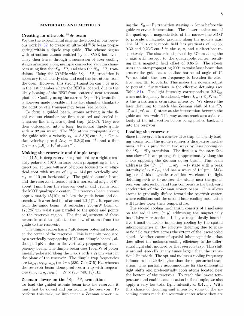
Fig. S1. |Spectra of narrow-linewidth cooling lasers,and their spatial extent. The right side represents thespectra of cooling lasers addressing the 1S0 − 3P1 transition(vertical red bars) with respect to the (relative) energy of thestates in the 3P1 manifold, shown on the left side. The en-ergies of these m′J states are given depending on the locationalong the z axis, and the horizontal black dashed lines repre-sent their respective Zeeman shifts when atoms are locatedinside the reservoir. The horizontal color bars at the bottomleft show the location and spatial extent of each laser beam,see also Table S1 for detailed beam parameters.
transparency laser light is blue detuned by 33 GHz fromthe 3.8 MHz-wide 3P1−3S1 transition at 688 nm. It con-tains two frequency components, 7 mW of right-hand cir-cularly polarized light and 3 mW of left-hand circularlypolarized light separated by 1.4 GHz. The magnetic fieldat the dimple location lays in the (y, z) plane and hasan angle of 60° with respect to the vertical y axis alongwhich the transparency beam propagates. This leads toa distribution of the light intensity onto the transitionsσ+, σ−, π of 1, 9, 6 for the left-hand and 9, 1, 6 forthe right-hand circular polarization.
The light is produced from a single external-cavitydiode laser, frequency shifted by acousto-optic mod-ulators and amplified by several injection-locked laserdiodes and a tapered amplifier. Since the 1S0 − 3P1 and3P1 − 3S1 lines are less than 1.5 nm apart, it is cru-cial to filter the light to prevent amplified spontaneousemission from introducing resonant scattering on the1S0 − 3P1 transition. This filtering is performed by asuccession of three dispersive prisms (Thorlabs PS853N-SF11 equilateral prisms), followed by a 2.5 m (right-hand circular) or 3.9 m (left-hand circular) propagationdistance before aperturing and injection into the finaloptical fiber.
Characterizing the transparency beam protec-tion
The transparency beam induced light shifts on the1S0− 3P1 transition were measured spectroscopically by
Fig. S2. |Loading of the reservoir and dimple at con-stant flux. We achieve a constant flux ΦG in the guideby switching the experiment on for 10 s without the Zeemanslower beam, until reaching a steady flow. We then switchthis beam on at time t = 0. We show (top) the BEC atomnumber and the phase-space density ρD in the dimple. Theblue dotted line indicates our BEC detection limit in termsof condensed atom number. We show (middle) the dimple,reservoir, and “reservoir+crossing” atom number, and weshow (bottom) the temperature TD in the dimple and thetemperature TRy in the reservoir along the vertical axis. Thedashed lines are the results from fits with exponential growthor decay, giving access to the (constant) fluxes, one-body lossrate parameters, and thermalization times (see text). Errorbars represent one standard deviation σ from binning on av-erage 6 data points.
probing the absorption of 88Sr samples loaded into thedimple. 88Sr is used instead of 84Sr since the higher nat-ural abundance improves signal without affecting the in-duced light shifts. Spectra are recorded for various trans-parency beam laser intensities at the magnetic field usedfor the CW BEC experiments. The results are shown inFig. S3c for one then two polarization components.
The observed light shifts are consistent with the cal-culated dressed states for the six coupled sub-levels ofthe 3P1 and 3S1 states. This is evaluated by solving theSchrodinger equation in the rotating frame of the lightfield for a transparency beam consisting of a single fre-quency, right-hand circular laser beam in the presenceof the measured external magnetic field. The theoret-ical results are given in Fig. S3c (solid lines, left side)with no adjustable parameters. We find a reasonableagreement with the observed shifts and reproduce the

11
0 1 2 3 4LHC light intensity (MW/m )2
-2
0
2
4
6
8
31
P(m
=-1
)e
ne
rgy
(×
MH
z)J
h
RHC(b)+LHCextrapolated & usedRHC(a)+LHCRHC(c)+LHC
0 2 4 6 8 10RHC light intensity (MW/m )2
-2
0
2
4
6
8
31
Pm
an
ifo
lde
ne
rgy
(×
MH
z)h
(a) (b) (c)
m = +1J
m = 0J
m = -1J
Operational intensityOperationalintensity
c
a b
Ene
rgy
Reservoir
z
Bz
By = 0.42 G B
Cooling
z
yg
3S1
3P1
1S0
mJ
-1 0 +1
33 GHz
Cooling
Transparencybeam
(π)
(σ+, σ-, π)
'
'
'
'
'
Left-hand circular (LHC), ω1
Right-hand circular (RHC), ω2
+
= 0.74 G
Fig. S3. |Light shift from the transparency beam. a,Level scheme showing laser cooling and transparency tran-sitions. b, Schematic of the potential energy landscape ofreservoir and dimple for the 1S0 and 3P1 states. Atoms arerendered insensitive to the laser cooling light by a single verti-cal “transparency” laser beam (green arrow), containing twofrequency components, one for each circular polarization. c,Transition energies to the three m′J = 0,±1 Zeeman sub-levels of the 3P1 manifold, referenced to the transition at zeroelectric and magnetic field (black dashed line). The energyshifts are shown for a single right-hand circular (RHC) polar-ization (left) and with the addition of the left-hand circular(LHC) component (right). We show the solutions (solid lines)of the Schrodinger equation for the 3P1 manifold coupled bya light field with single frequency component and RHC po-larization. In this case, at high laser intensities, the energy ofthe state originating from m′J = −1 saturates, correspondingto the presence of a dark state. The purple vertical dashedlines show the operational intensities of the LHC and RHClight fields used in the CW BEC experiment, and the purplediamond is extrapolated from the data.
expected saturation of the light shift due to the presenceof a dark state. An optimized fit can be obtained witha slightly higher intensity corresponding to a waist of21 µm instead of 23 µm, and a slightly modified polariza-tion distribution. In this fitted polarization distribution,the contribution of the weakest component, σ−, is en-hanced by a factor of roughly 2.5. Both differences canbe explained by effects from the vacuum chamber view-ports and dielectric mirrors.
When the left-hand circular polarization component ofthe transparency beam is added, we observe in Fig. S3c(right side) that the “dark” state shifts linearly away. Inthis manner all sub-levels of 3P1 can be shifted by morethan 4 MHz, more than 500 times the linewidth of thelaser cooling transition. For comparison, the light shifton the 1S0 ground state from the transparency beamis 20 kHz, and at most 380 kHz by all trapping beams,
about one order of magnitude smaller than the shift on3P1 states from the transparency beam.
We demonstrate the protection achieved by the trans-parency beam in two ways. Firstly, we measure thelifetime of a pure BEC inside the dimple in the pres-ence of all light and magnetic fields used in the CWBEC experiments. This pure BEC is produced before-hand using time-sequential cooling stages. Once the pureBEC is produced, we apply the same conditions as usedfor the CW BEC, except that the light addressing the1S0 − 1P1 transition is off, to prevent new atoms fromarriving. Without the transparency beam the 1/e life-time of a pure BEC in the dimple can’t even reach 40 mswhile with the transparency beam it exceeds 1.5 s.
Secondly, we show the influence of the transparencybeam on the existence of a CW BEC. Beginning withthe same configuration as the CW BEC but without thetransparency beam, steady state is established after afew seconds, with no BEC formed. We then suddenlyswitch the transparency beam on and observe the sam-ple’s evolution as shown in Fig. S4. While the reservoirsample seems unaffected, the dimple atom number in-creases by a factor of 6.4(1.8), indicating fewer losses.At the same time the sample (partially) thermalizes anda BEC appears after about 1 s. This demonstrates thecritical importance of the transparency beam.
Characterizing the BEC and thermal cloudTo characterize the CW BEC and surrounding thermalcloud, we switch all traps and beams off, and performabsorption imaging. Fitting the expanding clouds’ dis-tributions allows us to estimate atom numbers and tem-peratures throughout the system, as well as the numberof condensed atoms, all from a single image.
We begin with absorption images typically recordedafter an 18 ms time-of-flight expansion. The observed 2Ddensity distribution can be fitted by an ensemble of fourthermal components plus an additional Thomas-Fermidistribution when a BEC is present. Three independent2D Gaussian functions represent atoms originating fromthe dimple, the reservoir, and the crossing between theguide and reservoir. Atoms originating from the guideare represented along the guide’s axis by a sigmoid thattapers off due to the effect of the Zeeman slower, and inthe radial direction by a Gaussian profile. Examples areshown in Fig. S5.
We found this fit function with 18 free parameters tobe the simplest and most meaningful one capable of rep-resenting the data. By combining knowledge of theirdistinct locations and/or momentum spreads, we candetermine individually the populations and their char-acteristics. We find that the uncertainty in the fittedparameters is mostly insignificant compared to shot-to-shot variations in the data. An exception is distinguish-ing the population in the reservoir from the one in theguide-reservoir crossing region, where there is some am-biguity resulting in higher uncertainties. Both in themain text and these Materials and methods, the error

12
Fig. S4. |Influence of the transparency beam. We letthe experiment reach a steady state with the transparencybeam off. At t = 0 we switch the beam on and observe thesystem’s evolution. We show (top) the BEC atom numberand the phase-space density ρD in the dimple. The bluedotted line indicates our BEC detection limit in terms ofcondensed atom number. We show (middle) the dimple andreservoir atom number, and (bottom) the temperature TD inthe dimple and the temperature TRy in the reservoir alongthe vertical axis. Both atom number and temperature in thereservoir remain constant, while the dimple loads additionalatoms, indicating lower losses thanks to the protecting effectof the transparency beam.
bars indicate the standard deviation σ calculated frommultiple images. While it is possible to estimate thetemperatures in the y axis from a single fitted image,the initial cloud sizes in the z direction are large com-pared to the ballistic expansion. Thus we use a set ofmeasurements with varying times of flight to estimate zaxis temperatures.
When a BEC is present, it is necessary to add aThomas-Fermi profile to the previously discussed fitfunction. The only additional free parameter used inthe fit is the number of atoms in the BEC. We assumethat the BEC position is the same as the one of thenon-condensed atoms in the dimple and we calculate theBEC’s radii from the BEC atom number, the s-wavescattering length, the trap frequencies in the dimple, andthe expansion time [52]. These frequencies are calculatedfrom the knowledge of the waists of each relevant beamand of the powers used. The waists are either directlymeasured or extracted from observations of dipole oscil-
∆O
D
-0.07
0.07b g
id
c h
je
a thold = 2.2 s
y
z 1 mm
f thold = 3.2 s
y
z 0
0.5
Opt
ical
den
sity
Fig. S5. |Fitting a CW BEC. We show absorption pic-tures and their respective fits for two hold times, before (left,thold = 2.2 s) and after (right, thold = 3.2 s) the formationof the BEC. In the top row, we show absorption picturesa, f taken after 18 ms time-of-flight expansion. In the mid-dle row, we show results of fits b, g to these pictures, andthe fit residuals c, h. The fits use a 2D density distribu-tion fit function accounting only for a thermal cloud. Bycontrast, the bottom row shows both fits d, i and residualse, j with a 2D density distribution fit function including aThomas-Fermi distribution describing a BEC, in addition tothe thermal distribution. In presence of a BEC, the residualof the thermal-only fit h clearly shows a discrepancy at theBEC location, while the residual j demonstrates that the fitaccounts for the BEC.
lation frequencies of a pure BEC in the trap for severalbeam powers.
Adding an additional fitting parameter can lead tooverfitting. To rigorously determine whether includingthis Thomas-Fermi distribution provides a significantlybetter fit of the data, we employ a statistical F -test.This allows us to determine a BEC atom number thresh-old above which the fit is statistically better than theone without the Thomas-Fermi distribution. For this F -test we isolate a region of interest (ROI) in the imagecontaining both thermal and BEC atoms. We then cal-
culate the value F = (RRS1−RSS2)p2−p1 /RSS2
n−p2 , where RRSiis the residual sum of squares over the ROI for modeli with pi parameters, and n is the number of pixels ofthe ROI. The fit including the Thomas-Fermi distribu-tion is significantly better than the one without, only ifF is higher than the critical value of an F -distributionwith (p2 − p1, n − p2) degrees of freedom, with a de-sired confidence probability. By applying this test tothe data of Fig. 3, we find that the BEC model fitsbetter, with a confidence greater than 99.5 %, when theBEC atom number exceeds 2000. This sets our detectionlimit, above which we are confident a BEC exists. Im-portantly, this limit is lower than the BEC atom numbercorresponding to a −2σN shot-to-shot fluctuation. Thisindicates that, at all times after steady state is reached,a BEC exists.

13
Characterizing the reservoir loading
To estimate the flux ΦR of atoms loaded into the reser-voir we begin with all laser cooling and trapping beamson, except for the Zeeman slower beam. After some time,a steady state is reached, in which the guide is filledbut not the reservoir. We then switch on the Zeemanslower beam, and observe the loading of the reservoir,see Fig. S2. Using our fitting procedure for the absorp-tion images (see section “Characterizing the BEC andthermal cloud”), we estimate the growth in the num-ber of atoms in various regions of the cloud. With therough assumptions of a constant flux ΦR and a one-bodyloss rate parameter Γloss originating for example fromtransfer of atoms to the dimple, the loading of the reser-voir can be fitted by the exponential growth functionNR(t) = (1 − e−Γlosst) ΦR/Γloss. This function fits bestfor a flux ΦR = 1.4(2) × 106 atoms s−1, see Fig. S2. Wealso show the combined number of atoms loaded in thereservoir and “crossing” (guide-reservoir intersection) re-gions. We fit this data with a similar exponential growthfunction, and obtain a flux of 2.9(3)×106 atoms s−1. Therelative uncertainty of the combined atom numbers issmaller than for the data set describing only the reser-voir atom number. This is due to ambiguity between the“reservoir” and “crossing” regions in our fitting proce-dure.
Loading dynamics
The data of Fig. S2 show several timescales at play in thesystem’s evolution. First we see atoms populating thereservoir. About 500 ms later the dimple region beginsto fill. Finally about 1 s after the start of the dimpleloading we see a BEC begin to form.
These dynamics can be understood from the ther-malization timescale and from the need to exceed thecritical phase-space density to begin forming a BEC.We estimate the peak phase-space density evolution by
ρD = ND
(~3ωDxωDyωDz
k3BT3D
), where ND is the thermal
atom number in the dimple. However, this estimation isinaccurate because of the non-thermalized distributionfunction describing the atoms in the dimple (see section“Modeling of the BEC’s open dynamics” below). Wegive it here as an indication of the phase-space density,which with this definition and for a thermalized sampleshould be greater than 1.2 in order to produce a BEC.
Once the critical phase-space density is exceeded BECformation begins at a slow rate and then accelerates asmore atoms condense. Indeed, the growth of a BEC ormatter-wave is governed by Bose-stimulated scattering,which scales with the number of atoms occupying theground state of the trap [26, 29, 53, 54].
After about 3 s steady state is established. We probethe system for various hold times up to 5 min and findno indication that the BEC departs from steady state.This is exemplified in Fig. S2 and Fig. 3b.
BEC anisotropy after time-of-flight
A Bose-Einstein condensate and a thermal gas expandvery differently when released from a trap. A thermalgas expands isotropically, beginning with a shape remi-niscent of the initial trap geometry, and asymptoticallyapproaching an isotropic shape for long times of flight(TOF). By contrast, the expansion of a BEC releasedfrom an anisotropic trap remains anisotropic for longTOF, inverting its aspect ratio mid flight. This origi-nates from the anisotropic release of mean-field energy,which reflects the trap anisotropy [52].
The transpose-anisotropy provides an elegant methodby which to efficiently detect the presence of a CWBEC. The transpose-anisotropy of the density distribu-tion nOD is nsOD (y, z) − nsOD (z, y), where the origin ofthe coordinate system is at the density maximum. nsOD
is obtained from nOD by adding the same nOD distribu-tion rotated by 180°. Transpose-anisotropies for short(0.1 ms) and long (18 ms) TOFs are shown in Fig. S6.For 0.1 ms TOF, the density distribution shows a markedanisotropy as indicated by a strong cloverleaf pattern.This initial anisotropy is solely due to the action of thetrap geometry on the density distribution of the thermalgas, as the size of a potential BEC is below our imagingresolution. However, for 18 ms TOF we see a differencebetween pictures for short (2.2 s) and long (3.0 s) holdtime thold. For short thold the anisotropy is broad andsimply a remnant of the initial cloud anisotropy. How-ever for long thold, at which steady state is established,we see an additional, smaller cloverleaf pattern with op-posite anisotropy around the center of the picture. Boththe existence and the sign of this pattern are consistentwith the expansion of a BEC from a dimple with ourtrap frequencies.
Modeling of the BEC’s open dynamicsIn order to describe the formation and properties of thecontinuous-wave Bose-Einstein condensate, we develop amodel capable of fitting our experimental data, as shownfor example by the dashed blue line in Fig. 3b. In thefollowing we describe the model and its results.
Firstly, we lay out the model, which builds on thestandard Boltzmann kinetic theory of Bose gases withadditional dissipation to account for the open dynam-ics. As a main result of our derivation we arrive at therate equation Eq. (10). We provide details of the deriva-tion of each gain and loss term in the equation and theassumptions that led to them.
Secondly, we discuss the fit of this model to our data,from which we extract useful physical quantities, like the1- and 3-body loss rate parameters, and the flux into theCW BEC after reaching steady state.
In particular, we find that we are not able to describeour data if we assume that our system is in thermalequilibrium. This reflects the intrinsic driven-dissipativenature of the system.
The model — We model the dynamics of the BEC usingthe rate equation

14
Opt
ical
den
sity
0
0.5
∆O
D
Opt
ical
den
sity
0
4
∆O
D
thold = 2.2 s thold = 3.0 s
TOF = 0.1 ms
TOF = 18 ms
0.5 mm 200 µm
30 µm∆ = 1.33 Γ
∆ = 0
c
a b
d g
e f
h
0.5 mm -1.2
1.2
-0.07
0.07
Fig. S6. |BEC anisotropy after time-of-flight. a, e, Absorption images after short (0.1 ms) and c, g, after long (18 ms) free-expansion time-of-flight (TOF), for short (thold = 2.2 s, a, c) and long (thold = 3.0 s, e, g) trap loading times. Pictures a ande were imaged with a detuning of 1.33 Γ to avoid saturation. The regions of interest (corner-marked squares) centered aroundthe density maximums are analyzed in panels b, d, f, h, which show the transpose-anisotropy of the density distribution.This representation produces a cloverleaf pattern when the atomic cloud is anisotropic (see text). For short thold (left), thecloverleaf pattern, which appears because of how the trap geometry initially shapes the thermal cloud, keeps a constant signand diminishes during the expansion of a thermalized gas sample. For long thold (right), we observe at long expansion time han additional smaller cloverleaf pattern of opposite sign, which is indicative of the presence of a BEC.
nBEC(r) = sin(r)− sout(r)− γ1bnBEC(r)
−γ3b
[nBEC(r)3 + 6nBEC(r)2nth(r)
+6nBEC(r)nth(r)2],
(1)
where γ1b, γ3b are the phenomenological one- and three-body loss rate parameters, see [42], nBEC, nth are thelocal densities of the BEC and thermal atoms in thedimple, and we do not write explicitly the time de-pendence of the variables. In the framework of kineticBoltzmann equations, sin, sout are the collisional inte-grals (source terms) describing the exchange betweenthe thermal atoms and the BEC. To this end we followclosely the treatment in [55] and write (setting vBEC = 0in [55])
sin =nBECσ
πh3
∫dp3f3
1
v3
∫dvf4 (2a)
sout =nBECσ
h3
∫dp2f2∆v
∫dΩ
4π(1 + f3 + f4), (2b)
where σ = 8πa2sc is the s-wave scattering cross-section,
∆v =√v2
2 − 4v20 , v0 =
√gnBEC/m, g = 4π~2asc/m
and pj = mvj . Eq. (2a) describes the scattering oftwo thermal atoms with velocities v3 and v4 result-ing in a BEC atom and a thermal atom with velocityv2; Eq. (2b) corresponds to the opposite process. InEq. (2a) v4 = v + gnBEC
mv23v3 with v ⊥ v3 such that the
second integration is performed over the plane perpen-dicular to v3. In Eq. (2b) dΩ denotes the solid anglesubtended by v3 and v4. We use 84Sr atomic mass mand its s-wave scattering length asc = 122.8 a0, with a0
the Bohr radius. fj = f(r,pj) are the unknown distri-bution functions of the thermal atoms with the propertyNth =
∫dr dp/h3f(r,p).
In principle, one could obtain fj from complete N-body simulations [55] of the open system, accounting forthe coupled dynamics between the reservoir, the dimpleand the BEC. While strongly desirable, such a studygoes beyond the scope of the present analysis1. In-stead, let us first assume a thermal equilibrium suchthat f is given by the Bose-Einstein distribution. In thiscase the total number of non-interacting atoms in a har-monic trap is given by Nth = (βD~ωD)−3Li3
(e−βDµ
).
Here µ is the chemical potential of the distribution,ωD = (ωDxωDyωDz)
1/3, βD = 1/kBTD, and Lis(z) is apolylogarithm of order s. With the experimentally mea-sured dimple trap frequencies and gas temperature, wefind that even for the maximum allowed µ = 0, the atomnumber only reaches Nth ≈ 1.8 × 10⁵. This estimationis well below the measured value of 6.9(4) × 105 atomsin the dimple. To try to resolve this discrepancy, weperform a more refined calculation following [36], wherethe harmonic trapping potential is replaced by the com-bined potential of the reservoir and dimple traps, andwhere we account for the interactions between atoms.This calculation gives Nth ≈ 3.6 × 10⁵ atoms in reser-voir and dimple combined, which is less than those mea-sured in the dimple, let alone in the reservoir and dimplecombined (1.4(2) × 106). Unsurprisingly, in this calcu-
1 In this context, a possibility is to consider instead a simplerergodic description of the Bose-Einstein condensation [56–58].However, our preliminary analysis indicates breaking of the er-godicity assumptions, thus requiring the complete N-body sim-ulations.

15
lation most atoms are contained well within the dimple,as kBTD is much smaller than the dimple depth. The re-fined approach is thus also incapable of reproducing themeasured atom number. This is in direct contradictionwith our previous analysis in [36]. There, the refinedcalculation was capable of accounting for all atoms in atrap with a similar geometry, but where the continuousrefilling of the reservoir was absent. This difference leadsus to conclude that the current system does not fulfill thethermal equilibrium assumption due to its open charac-ter, and that the population dynamics are governed byout-of-equilibrium distribution functions f .
To proceed, we assume that the distribution functioncan be written as a product
f(r,p) = nth(r)f ′(p). (3)
We take f ′(p) = 1N e−βD
p2
2m , N = 4π(2π~)3
√π2
(mβD
) 32
to
be the Boltzmann distribution, which fulfills the normal-
ization property∫
d3p(2π~)3 f
′(p) = 1. We next specify the
densities nBEC(r) of the BEC and nth(r) of the thermalatoms appearing in Eq. (1). For the BEC we considerthe Thomas-Fermi profile given by
nBEC(r) = n0
(1−
(x
Rx
)2
−(y
Ry
)2
−(z
Rz
)2),
(4)
where Rα =√
2µD/m/ωDα, µD = ~ωD2
(15NBEC
ascaho
) 25
,
aho =√
~mωD
, NBEC is the total BEC atom number and
n0 = µD/g. In the BEC region, the condensate atomswill repel the thermal ones resulting, to a good accuracy,in the characteristic parabolic profile
nth(r) ≈
nth,0
[1 + γx
(xRx
)2
+ γy
(yRy
)2
+ γz
(zRz
)2],
(5)
where γα = (nc,α−nth,0)/nth,0. Next, motivated by theapproach in [36, 55], we determine the thermal densities
in the center, nth,0 = nth(0), and at the edge of theBEC cloud, nc,α = nth(Rα) in the direction α = x, y, z,self-consistently as
nth(r) = − 1
λ3dB
Li 32
[−e−βD(V (r)+2gnBEC(r)+2gnth(r)−η)
],
(6)
with λdB = h/√
2πmkBTD the thermal de-Broglie wave-length. Here, we need to stress that unlike in [36], thefunction in Eq. (6) is not the density corresponding tothe thermal equilibrium of a Bose gas as that one fails toreproduce the observed number of thermal atoms Nth,see the discussion above Eq. (3). The function in Eq. (6)in fact corresponds to a Fermi-Dirac distribution, whichhowever here does not have a particular physical signif-icance. It should be seen as a convenient ansatz fromwhich we extract nth,0 and nc,α, which has the advan-tage that it allows to match the observed number Nth
for positive values of the parameter η [59].The assumed prescription for nth(r) Eq. (6) is clearly
an idealization. Despite this fact, the model yields avalue for the three-body loss rate parameter γ3b thatis compatible with the values reported in the literature(see section The results below). We interpret this com-patibility as indicating that the values of nth,0 and nc,αextracted from Eq. (6) lie within a factor O(1) from theactual experimental values.
Next, we turn to the evaluation of the collisional in-tegrals Eqs. (2) using the distribution function Eq. (3)with the result
sin = nBECn2thσIin (7a)
sout = nBECnthσI(1)out + nBECn
2thσI
(2)out. (7b)
Here, we have introduced the functions
Iin = κv20K1(βDmv
20) (8a)
I(1)out = κN e−βDmv
20v2
0K1(βDmv20) (8b)
I(2)out = 2κj, (8c)
where κ = 1h3
1N 2
8πm3
mβD, K1 is the modified Bessel func-
tion of the second kind, and
j(r) =
∫ ∞2v0
dv2 v2e−βDm
2 v22
[e−
βDm
8 (v2−∆v(v2))2 − e−βDm
8 (v2+∆v(v2))2], (9)
which has to be evaluated numerically.
Ultimately, we are interested in the dynamics of thetotal number of the condensate atoms, which can be ob-tained by integrating Eq. (1) over the volume. To beable to carry out the final integration, we take the func-
tions Iin, I(1,2)out to be independent of the position2. Using
2 In principle, they still depend on spatial coordinates throughv0(nBEC(r)). For the span of experimental values of nBEC(r),this leads to a maximum variation by a factor 0.7.

16
the profiles (4),(5) we arrive at the final rate equation
NBEC = Sin − Sout − L1b − L(3)3b − L
(2)3b − L
(1)3b , (10)
where
Sin = n0n2th,0σV
(1,2)Iin (11a)
Sout = n0nth,0σV(1,1)I
(1)out + n0n
2th,0σV
(1,2)I(2)out (11b)
L1b = γ1bNBEC (11c)
L(3)3b = γ3bn
30V
(3,0) (11d)
L(2)3b = 6γ3bn
20nth,0V
(2,1) (11e)
L(1)3b = 6γ3bn0n
2th,0V
(1,2) (11f)
In the above equations, we have introduced the volumeintegrals
V (p,q) = 1/(np0nqth,0)
∫drnBEC(r)pnth(r)q, (12)
which evaluate to
V (1,1) = 4πRxRyRz2
105(7 + 3γ) (13a)
V (1,2) = 4πRxRyRz2
315(21 + 5G+ 18γ) (13b)
V (2,1) = 4πRxRyRz8
315(3 + γ) (13c)
V (3,0) = 4πRxRyRz16
315, (13d)
where
γ =1
3(γx + γy + γz) (14a)
G =1
5(γ2x + γ2
y + γ2z ) +
2
15(γxγy + γxγz + γyγz).
(14b)
To fit the data, we take γ1b, γ3b in Eqs. (11c)-(11f) asfree parameters and further parametrize Eq. (11a) andEq. (11b) as
Sin = αinn0n2th,0σV
(1,2)Iin (15a)
Sout = αoutαin(n0nth,0σV(1,1)I
(1)out + n0n
2th,0σV
(1,2)I(2)out)
(15b)
with αin, αout the fit parameters.
Fig. S7. |Modeling the onset and disappearance of theBEC. Evolution of the gas in the dimple. (left) BEC onsetwhen loading reservoir and dimple at constant flux ΦG inthe guide, started by Zeeman slower switch-on at t = −0.7 s(same data as in Fig. S2, but choosing a different origin forthe time axis). (right) BEC disappearance after setting ΦG tozero by switching the Zeeman slower off. The first two rowsshow the temperature and atom number of the thermal atomsin the dimple. The last two rows show the BEC atom numberand the estimated phase-space density ρD in the dimple. Thesolid blue line is the result of the fit of the BEC atom numberwith the model of Eq. (10). The dashed grey lines are resultsof fits with exponential growth/decay functions, which areused as input for Eq. (10). Error bars represent one standarddeviation σ from binning ∼ 4 data points. For the BEC atomnumber, due to the small number of data points, the errorbars can be underestimated compared to the, more reliable,characterization at steady state of σN = 2300 provided inthe main text. The phase-space density ρD is estimated frommeasurements of the atom number and temperature in thedimple (see text).
The results — We have simultaneously fitted 6 data setsof the onset of the BEC analogous to Fig. 3b, with slightvariations in the experimental starting conditions. Foreach of these sets, we use as a known time-varying inputour measurements of the time evolution of dimple atom

17
number and temperature (see for example the exponen-tial fits to the dimple data of Fig. S7). We use the rateEq. (10) and require the fit parameters γ1b, γ3b, andαout to be the same for all the data sets. Conversely, weallow independent variation for each data set of αin andthe initial BEC atom number NBEC(0), which providesthe seed to Eq. (10).
From this single fit, we obtain the loss rate param-eters γ1b = 6(2) s−1 and γ3b = 1.9(2) × 10−29 cm6/s.The value obtained for γ3b is compatible with the roughexperimental values reported in the literature, namely≈0.7 × 10⁻²⁹ cm6/s in [60] and 1.4(3) × 10−29 cm6/s.The latter value can be extracted from the data usedin [61], where the standard deviation is derived fromstatistical uncertainty, without accounting for system-atic effects. We also obtain the average flux intothe CW BEC at steady state Sin − Sout = 2.4(5) ×105 atoms s−1. In steady state, most of this incomingflux is compensated by the three-body losses involv-ing thermal atoms described by Eqs. (11e) and (11f),while the loss mechanisms Eqs. (11c) and (11d) areonly reaching a few 104 atoms s−1. Finally, we extractfrom the fit additional information about the CW BEC,namely the Thomas-Fermi radii RTFx, RTFy, RTFz =2.8(1), 1.2(1), 2.9(1) µm, the peak BEC density n0 =3.6(2) × 1020 atoms m−3 and the density of the thermalgas at the BEC center nth,0 = 3.6(1)× 1020 atoms m−3.
Fig. S7 shows example fits together with their corre-sponding experimental data sets. The left (“loading”stage) of Fig. S7 shows the onset and stabilization of theBEC following the switch on of the Zeeman slower beam.The right (“unloading” stage) of Fig. S7 shows the subse-quent data after suddenly switching off the same beam.This corresponds to stopping the atomic flux into thereservoir and leads to the disappearance of the BEC.It is apparent that the rate equation Eq. (10) captureswell the initial dynamics of the BEC atom number aswell as the initial dynamics of the unloading stage. Thediscrepancy for longer times during the unloading stagecan likely be attributed to the change of the momentumdistribution functions f(r,p). This arises from the si-multaneous thermalization and depletion of the dimpleatoms, which is not captured by the parametrization ofEqs. (15).
In summary, the rate equation (10) provides a satis-factory fit to the data, from which we obtain the loss rateparameters γ1b, γ3b and the steady-state BEC flux rateSin − Sout. A more comprehensive quantitative under-standing may be provided through further analysis start-ing from first principles. Such an analysis requires morecomplex modeling of the coupled dynamics between thereservoir, the dimple, and the BEC, such as the use ofthe ZNG theory [62, 63] and the related N -body simu-lations [55].