1 scope of slr review - infrastructure.gov.au · 1 scope of slr review slr consulting australia pty...
TRANSCRIPT

Department of Infrastructure and Regional Development Peer Review Report on the CPP Review of NASF Guideline B
12 September 2016 610.16245-L01-v1.0 BASF B Review 20160912.docx
Page 2
SLR Consulting Australia Pty Ltd
1 SCOPE OF SLR REVIEW
SLR Consulting Australia Pty Ltd (SLR) has been engaged by the Department of Infrastructure and Regional Development (DIRD) to review the report and associated guidance produced by Cermak Peterka Petersen (CPP) regarding the effectiveness of National Airports Safeguarding Framework (NASF) Guideline B – Managing the Risk of Building Generated Windshear and Turbulence at Airports.
The relevant report (herein referred to as the CPP Report) is:
“Technical Review of NASF Guideline B”, CPP Project 9315, July 2016.
As the context for SLR’s peer review, we understand that DIRD seeks to ensure that NASF Guideline B reflects world’s best practice and available science and encourages the use of the latest assessment technologies and methodologies in the application of the guideline.
Our Peer Review is broken up into the following sections:
Section 2 General comments on the overall direction taken within the CPP Report
Section 3 Comments on the proposed changes to NASF Guideline B ( refer CPP Report Table 6 )
Section 4 Comments on the CPP Report 5.2 – Review of External Queries
Section 5 Comments on the CPP Report 6 – Next Steps
Appendix A Comments on CPP Report Table 4 ( Guidance notes relevant to Wind Tunnel Assessment Methodologies )
Appendix B Comments on CPP Report Table 5 ( Guidance notes relevant to CFD-Based Simulation Methodologies )

Department of Infrastructure and Regional Development Peer Review Report on the CPP Review of NASF Guideline B
12 September 2016 610.16245-L01-v1.0 BASF B Review 20160912.docx
Page 3
SLR Consulting Australia Pty Ltd
2 GENERAL COMMENTS ON THE CPP REPORT
2.1 Overall Observation
As pointed out in the CPP Report, there appears to have been considerable uncertainty and variability in methodology associated with the assessment of new airport developments following the publication of NASF Guideline B (produced by SLR).
The CPP Report therefore represents a timely update of the original NASF Guideline B.
The CPP Report retains a strong connection to the original and extensive work carried out by NLR which led to guidance and supporting documentation covering building wake impacts on runway operations, a body of work which has received widespread acceptance within the global airport/airline industry.
2.2 Proposed Inclusion of Turbulence Criterion
The absence of the NLR 4-knot (RMS) turbulence criterion within the original NASF Guideline B has been noted as a significant exclusion. The reasons behind this (perhaps only of historical interest now) are as follows:
Clearly, turbulence can have an adverse impact on aircraft operations, especially during take-off and landing.
Such adverse impacts however are not intrinsically related to building-induced wake flow impacts, ie challenging turbulence conditions during take-off and landing can exist in the absence of any significant building wake disturbance effects.
In fact, the general impact of buildings located nearby to runways, under more or less cross-wind conditions, is to provide an overall lowering of wind speeds downstream (ie in the building wake) with a drop in turbulence magnitude along with the magnitude of mean wind.
For aircraft landing in more or less cross-wind conditions, it is the transition from (1) first a strong cross-wind to (2) second, low speed wake flow behind a building and then (3) back again to a strong cross-wind, which causes potentially adverse aircraft responses, hence the NLR mean wind deficit criteria.
RMS wind speeds (turbulence) will likely be greater in magnitude outside of the building wake flow (normally characterised by low winds). Accordingly, it is winds beyond the extent of a building wake disturbance that are usually of greatest concern in relation to NLR’s 4 kt turbulence criterion.
The above can be summarised as follows:
The exceedance or otherwise of NLR’s mean wind deficit criteria increase in likelihood with the addition of a new building of sufficient size and in close proximity to the relevant runway.
The exceedance or otherwise of NLR’s 4-kt turbulence criterion is almost certainly unlikely to be impacted by the addition of a new development and its associated building wake impacts.
The original NASF Guideline B was designed to address building wake impacts per se, hence the absence of mention of the 4-kt turbulence criterion (which was however included in SLR’s extensive background document to the guideline).
In retrospect, it is logical that NASF Guideline B would have been a useful document to include the NLR 4-kt turbulence criterion, even though airport wind conditions leading to potential exceedances of this criterion were not likely to be associated with building wake disturbance impacts.
It is noted that the addition of the NLR 4-kt turbulence criterion within NASF Guideline B serves a dual purpose. SLR’s own airport studies (and no doubt those of other consultants) have shown that, in specific new building circumstances, the turbulence criterion might well be exceeded before winds reach a level where the other NLR mean wind speed deficit criteria are triggered.

Department of Infrastructure and Regional Development Peer Review Report on the CPP Review of NASF Guideline B
12 September 2016 610.16245-L01-v1.0 BASF B Review 20160912.docx
Page 4
SLR Consulting Australia Pty Ltd
Despite the fact therefore that Consultants (including SLR and CPP) have in fact been using the NLR 4-kt turbulence criterion in addition to the NASF Guideline B mean wind speed deficit criteria in such studies, SLR is in agreement as to the benefits of its inclusion in a revised NASF Guideline B which ostensibly relates to building wake impacts.
2.3 Proposed Inclusion of Double Mean Wind Deficit Criteria
The use of only a single mean wind deficit criterion within the original NASF Guideline B has also been noted as a significant exclusion. The reasons behind this are as follows:
The initial impetus for NLR to develop some form of guidance in relation to wind disturbance due to structures near runways arose from wake effects observed in the vicinity of an engine test run facility at Schiphol Airport. Those wake effects were deemed the cause of pilot reports of heavy disturbances at low heights under strong SSW winds (runways 22 and 27).
The initial guidance from NLR designed to address this issue was …
“The difference in wind velocity perpendicular to the aircraft over a short interval may not exceed 7 knots”
It was quickly realised that this guidance did not specify what a “short interval” was and furthermore did not account for any mean wind deficit in the longitudinal direction, ie the wind velocity in line with the aircraft along the runway axis. Finally, there was no mention of turbulence.
These “gaps” then led to the second round of NLR guidance which the CPP Report proposes to be included in a revised NASF Guideline B. The second round of NRL guidance had the following two mean wind speed deficit criteria.
“The variation in mean wind speed due to wind disturbing structures must remain below 7 knots along the aircraft trajectory at heights below 200 ft. The speed deficit change of 7 knots must take place over a distance of at least 100 m”
“The variation in mean wind speed due to wind disturbing structures must remain below 6 knots across the aircraft trajectory at heights below 200 ft. The speed deficit change of 6 knots must take place over a distance of at least 100 m”
SLR only included the original (and single) mean wind speed deficit criterion in the original NASF Guideline B for the following reasons:
The original NLR guidance was explicit (and hence not prone to mis-interpretation) in its description of the exceedance wind parameter of interest, namely the wind velocity perpendicular to the aircraft. This wind is referred to in common word usage as a “cross-wind”.
The amended NLR double mean wind speed criteria guidance was not explicit – a fact which is acknowledged in the CPP Report (page 2) where it is stated that … “the criteria description are unclear”. The CPP Report also refers (page 2) to the more commonly used word wind velocity descriptors … “along-wind” (in line with the aircraft track) and “cross-wind” (perpendicular to the aircraft track).
Furthermore, from a practical perspective, it is difficult to envisage any circumstance under which an obstacle of practical concern, ie a likely airport building, could actually generate an along-wind deficit criterion exceedance before the cross-wind deficit criterion was already triggered.
Put simply, any (realistic) airport building that causes an along-wind criterion exceedance would trigger the across-wind criterion at much lower wind speeds … when the wind was blowing close to perpendicular to the runway axis. This is reflected in the Airport Building Assessments which SLR has reviewed from other Consultants as well as our own work, where the wind directions of interest in any analysis of building wake effects are always those that generate the highest cross-winds on the runway(s) of interest.
SLR acknowledges that along-wind disturbances are a cause for concern for aircraft either landing or taking off. However, the governing wind conditions of interest in relation to building wake effects are those associated with cross-winds.

Department of Infrastructure and Regional Development Peer Review Report on the CPP Review of NASF Guideline B
12 September 2016 610.16245-L01-v1.0 BASF B Review 20160912.docx
Page 5
SLR Consulting Australia Pty Ltd
Again, in summary … to avoid the opportunity for mis-interpretation, SLR simply adopted the original NLR cross-wind exceedance guidance in the original NASG Guideline B, also being the governing criterion (when compared to the along-wind criterion).
SLR acknowledges that the omission of the revised double NLR mean wind deficit criteria has caused concern simply through a perception of omission. For this reason, and given that it will make no practical difference to building development approvals, we are happy for the double mean wind deficit criteria to be included in a revised NASF Guideline B.
2.4 Proposed Inclusion of “Quality Assurance” Guidance
The inclusion of guidance notes in relation to both Wind Tunnel Testing and CFD Simulation technical quality parameters would appear to be necessary on the basis of apparent significant variability revealed by CPP in the methodologies used by consultants (whether they be Wind Experts or not) in the study of building impacts on runway operations. We make the following observations:
Wind Tunnel Testing
All of the key specific aspects of wind tunnel testing necessary to carry out a whole range of wind engineering studies have been well established and well documented for many years now. Such testing includes:
environmental winds for pedestrian comfort
cladding pressure studies for building façade loads
structural wind load studies to establish high-rise building deflections and accelerations
pollutant dispersion studies, etc.
This has resulted in Wind Engineering “Manuals” being produced by a number of nations, all of which share virtually identical specific technical recommendations for carrying out such studies.
In fact, the CPP Report makes reference to one of these, the AWES Manual covering Wind Engineering Studies of Buildings, developed in 2001.
Extensive validation studies (supporting such Manuals and numerous National Wind Codes) commenced in the late 1960’s and continued through to this day.
Wind Tunnel Testing is therefore a “mature” science, and perhaps somewhat unusually, one where there is more or less global agreement as to all of the main technical factors that need to be taken into account in conducting a wide range of standard wind tunnel tests (refer listing above following the first bullet point).
CFD Simulations
The same cannot be said for CFD Simulation methodologies:
This is NOT because CFD Simulations are not able to provide reliable predictions of various windflow impacts.
Rather, CFD Simulation methodology has seen a rapid evolution just in the past decade alone, associated with an exponential growth in the computational power available to carry out such simulations.
As a result of the above, the CPP Report has correctly identified the potential for significant variations in CFD Simulation methodology to be employed by consultants (even amongst those who can reasonably claim to be “Wind Experts”)
Accordingly, SLR sees significant benefit in the incorporation of the kind of information provided in CPP Table 5 within the revised NASF Guideline B.
It is strongly recommended however, that these guidance notes be subject to wide review and feedback (ie beyond both CPP and SLR) to achieve the right balance between “consistency” and “flexibility” to allow for the rapid strides this exciting area of engineering fluid dynamics is currently experiencing.

Department of Infrastructure and Regional Development Peer Review Report on the CPP Review of NASF Guideline B
12 September 2016 610.16245-L01-v1.0 BASF B Review 20160912.docx
Page 6
SLR Consulting Australia Pty Ltd
3 COMMENTS ON PROPOSED NASF GUIDELINE B MODIFICATIONS
Clause No Current Wording Proposed Wording SLR Comment
10 Buildings that could pose a safety risk are those located:
a. 1200 m or closer perpendicular to the runway centreline; or
b. 900 m or closer in front of runway threshold (ie towards the landside of the airport); or
c. 500 m or closer from the runway threshold along the runway.
Buildings that could pose a safety risk are those located:
a. 1200 m or closer perpendicular to the extended runway centreline; and
b. 900 m or closer in front of runway threshold (i.e. towards the landside of the airport); or
c. anywhere along the length of the runway
Agreed
12 The guidelines set out:
empirically determined criteria for windshear and turbulence respectively;
generic guidance on mitigating risks from proposed buildings;
a methodology for assessment of proposed buildings; and
options, where required, for subsequent detailed modelling of wind effects.
options to mitigate wind effects of existing buildings where required
The guidelines set out:
empirically determined criteria for windshear and turbulence respectively;
generic guidance on mitigating risks from proposed buildings;
a methodology for assessment of proposed buildings; and
options, where required, for subsequent detailed modelling of wind effects.
Unsure as to the reasons for the exclusion of mitigation options within the Guideline.
Refer also additional comments below.
23 The Australian Government committed in the Aviation White Paper to develop guidance on the impact of turbulence and wind shear generated by buildings in the vicinity of runways. To date, no formal regulation exists in Australia or indeed anywhere in the world on the assessment and mitigation of turbulence and wind shear generated by buildings.
Modify as per latest update to NASF Guideline B. Remove reference to White Paper.
Agreed
25 Leased federal airports are protected from tall buildings in the vicinity of airports based on standards established by the International Civil Aviation Organisation (ICAO). These standards form the basis of ‘prescribed airspace’ legislation under the Airports Act 1996 which is administered by the Department of Infrastructure and Transport (DoIT). Under this legislation, airspace surrounding leased federal airports is regulated to ensure that obstacles to safe air transport are not built.
Leave unchanged Agreed

Department of Infrastructure and Regional Development Peer Review Report on the CPP Review of NASF Guideline B
12 September 2016 610.16245-L01-v1.0 BASF B Review 20160912.docx
Page 7
SLR Consulting Australia Pty Ltd
27 Australia has international obligations as a contracting state to the Convention on Civil Aviation to regulate aviation safety. As discussed previously, neither ICAO nor any other major aviation safety regulator has so far established wind impact assessment criteria
Leave unchanged Agreed
28 Current practice is generally to rely on standing warnings to pilots about the potential to encounter adverse wind effects. This is the approach in the UK as well as currently in Australia. For example, at Canberra Airport, there is a permanent notice in aviation publications advising pilots about the potential adverse wind effects that can be encountered because of a hangar. After extensive consultation and research, Australian governments have decided to take a pro-active approach on this issue and this option has been discarded.
Modify as per discussions Feedback required here from relevant third parties
31 For buildings that do not meet the 1:35 rule, an alternative approach is required. This approach is:
the adoption of a windshear criterion to be applied as the basis of regulatory controls.
For buildings that do not meet the 1:35 rule, an alternative approach is required as the basis of regulatory controls:
the adoption of along-wind and cross-wind windshear criteria
the adoption of turbulence criteria
A grammatical suggestion
For buildings that do not meet the 1:35 rule, an alternative approach is required as the basis of regulatory controls:
the adoption of along-wind and cross-wind windshear criteria, and
the adoption of a turbulence criterion
33 Based on this research, NLR developed the following criterion:
Based on this research, NLR developed the following criteria:
34 The variation in mean wind speed due to wind disturbing structures must remain below 7 knots along the aircraft trajectory at heights below 200ft. The speed deficit change of 7 knots must take place over a distance of at least 100m.
The variation in mean wind speed due to wind disturbing structures must remain below:
7 knots along the aircraft trajectory at heights below 200 ft. The speed deficit change of 7 knots must take place over a distance of at least 100 m.
6 knots across the aircraft trajectory at heights below 200 ft. The speed deficit change of 6 knots must take place over a distance of at least 100 m.
The standard deviation of wind speed must remain below 4 knots below 200 ft.
Agreed
37 The most critical zone (in plan view) for building positioning, with respect to potential (building-related) windshear problems, is close to the touch‐down zones of runways.
The most critical zone (in plan view) for building positioning, with respect to potential (building-related) wind shear problems, is close to the touch-down zones of runways.
Critical zones with respect to potential turbulence problems are more difficult to predict as they depend more heavily on building shape and local surrounds.
Agreed

Department of Infrastructure and Regional Development Peer Review Report on the CPP Review of NASF Guideline B
12 September 2016 610.16245-L01-v1.0 BASF B Review 20160912.docx
Page 8
SLR Consulting Australia Pty Ltd
39-42 Statements about building orientation and width/depth ratio
Move to and amend in guidance material
Does not consider multiple wind directions, and provides recommendations that would not necessarily result in compliance with turbulence criteria
These clauses provide initial qualitative advice (eg alerting proponents to issues surrounding oblique-oriented buildings and the incidence of “delta” vortices (which happens to have been an important element of the windshear problem which led to the original NLR criteria). Furthermore, the wording in Clause 41 does in fact alert the proponent to the potential for non-perpendicular wind directions to cause windshear problem.
46 Like all aviation safety incidents, building-induced windshear events involve a coincidence of factors including the following:
There would need to be a building of shape and size able to generate wake disturbances large enough to exceed accepted windshear criteria, eg the NLR “7-knot criterion”.
The wind would need to be blowing in a more or less cross‐wind orientation to the runway being used and of a magnitude able to generate conditions where the “7-knot criterion” could be exceeded.
Like all aviation safety incidents, building-induced windshear events involve a coincidence of factors including the following:
There would need to be a building of shape and size able to generate wake disturbances large enough to exceed accepted windshear and turbulence criteria
The wind would need to be of a magnitude sufficient to create an exceedance of one of the three criteria
The wind direction would need to create exceedances that intersect the measurement plane.
Aircraft would have to be operating in the measurement plane
These proposed new bullet points seem to overlap; suggest the following wording:
There would need to be a building of shape and size able to generate wake disturbances along the aircraft operating assessment plane, large enough to exceed any one of the accepted windshear and turbulence criteria
The above implies a combination of wind speed (of sufficient magnitude) and wind direction that favours adverse windshear and turbulence conditions at the aircraft operating assessment plane.
48-59 Details on calculating building wake deficit for wind shear criteria desktop assessment
Delete
Becomes redundant with the addition of the turbulence criteria, since no simple procedure is available for that assessment.
These clauses were aimed primarily at smaller airports which would give a proponent and airport operator a simple procedure to avoid a costly Wind Tunnel or CFD study in the case of simple rectangular stand-alone buildings. They do not become redundant with the addition of the NLR turbulence criterion, which can be assessed, again in “simple” airport environments by reference to the AU Wind Code AS1170.2.
60 A wind consultant or other suitably qualified professional should be asked to provide guidance on the acceptability or otherwise of a proposed building development in relation to the potential wake disturbance caused by the building on nearby runway operations.
Add:
The wind consultant or other suitably qualified professional shall comply with the QAM provided in the guidance material
Cannot agree with the “add” recommendation in principle until the QAM is finalised.
Certainly, the Wind Tunnel Testing QAM suggestions put forward in CPP Table 4 are straightforward and non-controversial (Wind Tunnel Testing has been pretty well “normalised” globally for many years).
The same cannot be said for CFD Simulation techniques, which have been evolving rapidly the past few years, and hence the need for discussion regarding the suggested QAM elements in CPP Table 5.

Department of Infrastructure and Regional Development Peer Review Report on the CPP Review of NASF Guideline B
12 September 2016 610.16245-L01-v1.0 BASF B Review 20160912.docx
Page 9
SLR Consulting Australia Pty Ltd
This assessment will be premised on the acceptance criterion, viz. whether the “7-knot criterion”, will be exceeded or not, and, if it is predicted to be exceeded, how often.
This assessment will be premised on the acceptance criteria, viz. whether the wind-shear and turbulence criteria will be exceeded or not. If exceeded, an assessment of the expected impact on aircraft operations is required and discussions with the airport are triggered unless the structure is modified to pass the criteria with additional testing.
Agreed
66 For buildings that do not meet the 1: 35 rule, the assessment hierarchy methodology is described in Table 2 - Cases B1, B2 and C.
For buildings that do not meet the 1: 35 rule, the assessment hierarchy methodology is described in Table 2 - Cases B1, B2 and C.
Table simplified to include 4 items:
A: Meet the 1:35 rule
B1: Fail the 1:35 rule but structure deemed to have no impact based on simple assessment
B2: Fail the 1:35 rule but deemed to have no impact after detailed wind tunnel or CFD analysis
C: Fail the 1:35 rule, testing and discussions with airport required
Note:
Case B1 designed to exempt structures such as cranes and chimneys which do not pose a risk to aircraft in terms of wind shear and turbulence generation.
These criteria are currently under development
Very useful to include case B1.
What does “simple” assessment mean in B1 ?
Depending on the final wording of B1, bullet points B2 and C seem logical
67 The output of the consultant’s wind assessment for cases B1, B2 and C will typically be of the form displayed in Figure 5.
Delete.
This plot is of little use to stakeholders.
Replace with: The output of the consultant’s wind assessment will provide information relating to the expected impact on standard operating procedures at the airport in question for further discussions with stakeholders.
This plot was inserted to make proponents aware that the exceedance of any agreed criteria has a “statistical” dimension to it.
For example an exceedance might occur once per week (which presumably would be of considerable concern) or once every 100 years (which would presumably be of significantly less concern, and likely able to be managed operationally by the airport)
If it is felt that aircraft operators are not interested in the statistical characteristics of windshear and/or turbulence exceedances (ie how often they occur), Figure 5 would indeed be of little use, unless words can be inserted to provide a comparable awareness of the issue of exceedance recurrence interval.
Department of Infrastructure and Regional Development Peer Review Report on the CPP Review of NASF Guideline B
12 September 2016 610.16245-L01-v1.0 BASF B Review 20160912.docx
Page 10
SLR Consulting Australia Pty Ltd
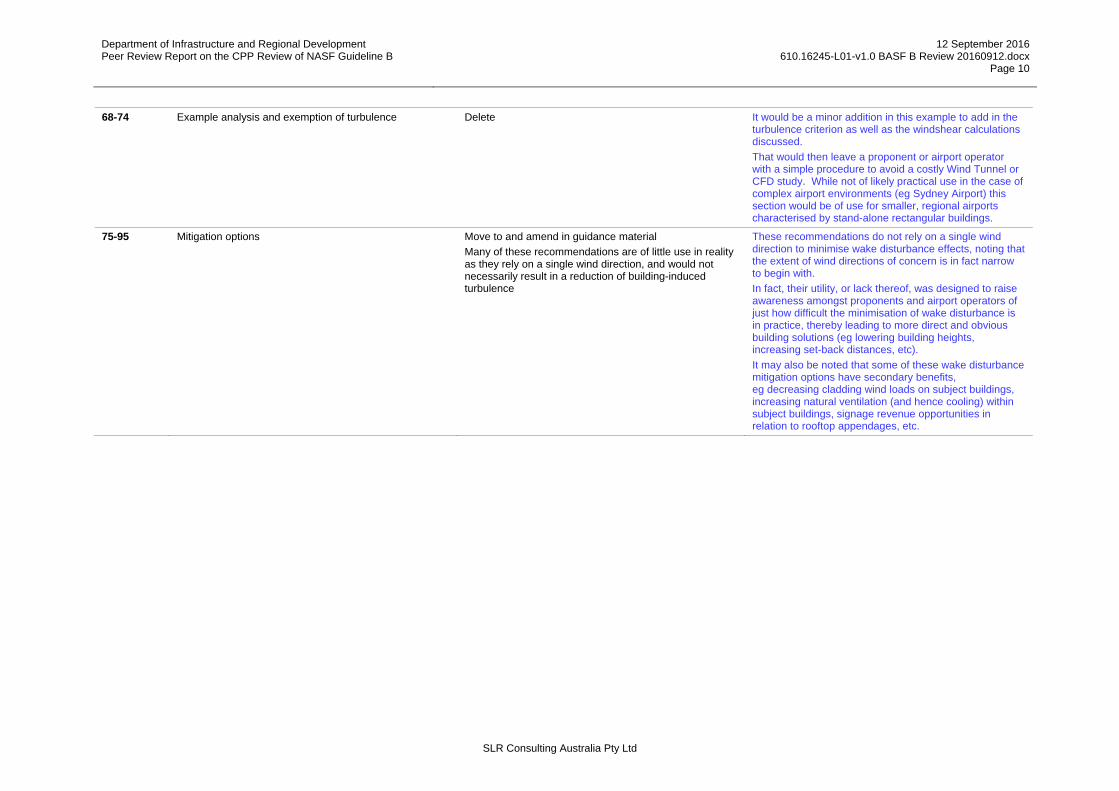
68-74 Example analysis and exemption of turbulence
Delete
It would be a minor addition in this example to add in the turbulence criterion as well as the windshear calculations discussed.
That would then leave a proponent or airport operator with a simple procedure to avoid a costly Wind Tunnel or CFD study. While not of likely practical use in the case of complex airport environments (eg Sydney Airport) this section would be of use for smaller, regional airports characterised by stand-alone rectangular buildings.
75-95 Mitigation options
Move to and amend in guidance material
Many of these recommendations are of little use in reality as they rely on a single wind direction, and would not necessarily result in a reduction of building-induced turbulence
These recommendations do not rely on a single wind direction to minimise wake disturbance effects, noting that the extent of wind directions of concern is in fact narrow to begin with.
In fact, their utility, or lack thereof, was designed to raise awareness amongst proponents and airport operators of just how difficult the minimisation of wake disturbance is in practice, thereby leading to more direct and obvious building solutions (eg lowering building heights, increasing set-back distances, etc).
It may also be noted that some of these wake disturbance mitigation options have secondary benefits, eg decreasing cladding wind loads on subject buildings, increasing natural ventilation (and hence cooling) within subject buildings, signage revenue opportunities in relation to rooftop appendages, etc.

Department of Infrastructure and Regional Development Peer Review Report on the CPP Review of NASF Guideline B
12 September 2016 610.16245-L01-v1.0 BASF B Review 20160912.docx
Page 11
SLR Consulting Australia Pty Ltd
4 COMMENTS ON CPP Report 5.2 – Review of External Queries
SLR has no substantive comments to add to those already supplied by CPP in response to the queries it has received in relation to this project.
5 COMMENTS ON CPP Report 6 – Next Steps
The responses below refer directly to the relevant CPP Report Section 6 sub-clauses
6.1.1 Clarifying NLR definitions, interpretations, and intent
SLR agrees that all relevant aspects of the original NLR documentation should be clarified, so that none of the key exceedance criteria are open to any further interpretation issues.
A case in point is the adoption of the NLR 4-kt turbulence criterion. While the other two mean wind speed deficit criteria state a distance parameter (namely 100 m) for their assessment, the turbulence criterion is left as a stand-alone statement.
For example … Suppose a study identifies an exceedance of the 4-kt turbulence criterion which is found to occur only over a very small distance (say less than 10 m) Would this constitute a “fail” regarding this criterion ?
6.1.2 Detailed review of NLR research and criteria as it relates to airport operations management.
SLR spent considerable time during the production of the original NASF Guideline B studying the extensive body of NLR research and associated reports. A further look at this body of work may possibly yield improved criteria in the context of Australian airports.
It is noted that the adoption of the mean wind speed deficit criteria along with the turbulence criterion involves significant effort (in terms of building development applications) to ensure consistency of application, assessment and result presentation.
6.1.3 Link between NASF and current operational procedures
SLR agrees that there is ample room for increased integration between the assessment and approval of airport building developments, the operational procedures adopted by a given airport and the undoubted instinctive and well-honed responses which both Air Traffic Controllers and Pilots deploy in adverse weather conditions.
It would seem that NASF Guideline B provides a potentially useful vehicle to increase this alignment.
Department of Infrastructure and Regional Development Peer Review Report on the CPP Review of NASF Guideline B
61
SLR Consulting Australia Pty Ltd
6.1.4 Criteria for smaller aircraft
Careful thought needs to be given in terms of the application of the NLR criteria for mean wind speed deficit and turbulence to very light aircraft. As noted in the CPP Report, the smallest aircraft considered in the various NLR studies was a Fokker 100. In general, aircraft manufacturers specify higher cross-wind operational tolerances for larger aircraft. It follows logically (as suggested in the CPP Report) that the NLR criteria should be more stringent for the GA category. Without a deeper understanding however of the aircraft flight responses for such aircraft, caution should be used in simple “extrapolation” type criteria. That said, the CPP Report suggestions appear to represent a reasonable starting point and should be given further review.
6.1.5 Benchmarking criteria against full scale data and operational events
The CPP Report states that the NLR research was primarily based on wind tunnel testing, and piloted and non-piloted simulator based experiments. In fact, CFD simulations were also used in the development of the adopted criteria.
The original NASF Guideline B background supporting document contained a section on problematic airport landing “events” that were confidently predicted to have been associated with building-induced wake effects. Such events are also +a prime source of “real world” benchmarking to be used in the development and application of guidelines such as NASF Guideline B.
6.1.6 Criteria for Helicopters
Operational criteria do in fact exist for helicopter operations (not covered within NASF Guideline B).
Such criteria are used in some countries for example in the operational constraints applying to helipads on high-rise buildings and by all global oil majors in relation to oil rig helipads, which have further constraints regarding proximity to flare stacks, etc.
6.1.7 Continuing general research.
No SLR Comment.
6.2 Recommendations for how this could be carried out
Like CPP, SLR has experience working with University and other R&D-oriented organisations on research funded projects. Indeed, both consultancies have Principals who have spent considerable time working in University environments - The University of Sydney in the case of CPP, The University of Western Ontario in the case of SLR.
Given the evident variances in study methodologies amongst the consulting community that has already been identified by the CPP Report in relation to this topic, SLR suggests that there may be an opportunity for consultancies like SLR and CPP to work jointly, and in combination with academic partners to pursue the kind of grant opportunities available both here in Australia, and potentially, overseas, given both organisations’ network of global offices.
Department of Infrastructure and Regional Development Peer Review Report on the CPP Review of NASF Guideline B
61
SLR Consulting Australia Pty Ltd
6 COMMENTS ON CPP Report – Appendix 2
The CPP Report Appendix 2 provides an extended description of the various ways that the wind can vary, in both a time-wise sense (ie at a single location) and locational sense (ie between two different positions), giving rise to terms like …
Windshear, Turbulence, Turbulence Intensity, etc
There are numerous ways that such variations in wind speed and wind direction can be described and/or defined resulting in slightly different terminology in use within the various professions of relevance: Wind Engineering, Meteorology, Weather Forecasting, etc.
From a wind engineering perspective, the distinction between windshear and turbulence is well understood, at least in so far as wind speed is concerned.
Windshear normally refers to a change in the mean wind velocity from one location to the next.
The change can occur vertically, eg the difference in mean wind speed close to the ground compared to higher up in the atmosphere.
The change can occur horizontally, eg the difference in mean wind speeds in a horizontal plane behind a building, between the outside of the wake and inside the wake.
Turbulence normally refers the ongoing instantaneous changes in wind speed at any one location, above and below the mean wind speed.
There is an interesting absence of a comparable set of “common usage” terms, amongst all relevant professions, to describe the parallel variations that occur with wind direction. Just as in the case of the wind speed, the wind direction is constantly changing, resulting in a mean wind direction and instantaneous wind direction fluctuations. No common colloquial terms have been developed to describe the change in mean wind direction from one location to another (ie the equivalent to windshear but for wind direction) or the instantaneous fluctuations of wind direction at any one location (ie the equivalent of turbulence). Meteorologists and sailors often use the term “wind shift” to describe a change in wind direction, and it is generally assumed that this applies to the mean wind direction; no such term is in common usage to describe instantaneous wind direction fluctuations.
Windshear and turbulence can arise from many different sources, eg the frictional influence of trees and buildings, etc, on the ground, topographic features such as hills and escarpments, etc. They will also vary according the relevant weather phenomenon (refer examples provided in the SLR Background Reference document to the original NASF Guideline B). These are clearly of more than just academic interest to wind engineers, meteorologists, etc.
It is important to note that, in so far as NASF Guideline B is concerned, the key issue of interest is the wake caused by buildings located close to runways and the wind variations (both mean wind and turbulence) associated with those wakes.
As long as these wind disturbances are explicitly described, ie the variation in cross-wind experienced by an aircraft passing through a building wake zone, the occasional variable use of terminology of words like windshear and turbulence should not present an obstacle to a clear and transparent process of handling building development approvals within airport precincts.

Appendix A 610.16245-L01-v1.0 BASF B Review 20160912.docx
Page 1 of 4
SLR Comments on CPP Report Table 4 Requirements for Wind Tunnel Based Modelling Studies
SLR Consulting Australia Pty Ltd
Requirement Discussion Test Requirements Reporting Requirements
Model Geometry A model scale should be chosen in order to represent all nearby influential building structures as well as incorporate the subject structure and the appropriate portion of the runway glideslope. Typically, this scale is in order of 1:500 to 1:1000. The model should generally be designed and constructed in accordance with Part A of the Australasian Wind Engineering Society (2001).
The consultant’s report should include a description of the subject building or structure, photographs of the wind tunnel model and a plan view drawing of the wind tunnel model including surrounds
SLR Comment It is noted that the above-mentioned reference AWES-QAM-1-2001, “Wind Engineering Studies of Buildings”, provides much of the information detailed in CPP Report Table 4 and is well known to all consultants involved in wind tunnel testing.
The consultant’s report should include a description of the subject building(s) or structure(s), photographs of the wind tunnel model and drawings of the wind tunnel model including surrounds, including airport environ site plans and subject building elevations.
Atmospheric Boundary Layer Classification
One the key characteristics of these studies is the modelled atmospheric boundary layer (ABL), which is the governing input into the model as well as a reference of existing conditions at the edge of the modelled area. It is particularly important in many airport studies due to absence of large or closely spaced buildings within the modelled area which would otherwise perturb the input condition
A suitable ABL classification should be selected from an appropriate engineering standard, for Australian airports this would typically be Standard Australia (2011) and be calibrated in accordance with the Australasian Wind Engineering Society (2001). During calibration the ABL should be characterised in terms of vertical velocity profile, vertical turbulence intensity profile and spectral distribution of turbulence. The calibration should also ensure appropriate propagation of the modelled ABL from the edge of the test area to the location of measurement.
The consultant’s report should include a brief description of the chosen ABL classification/s and calibration procedure. Graphical, illustration must be provided showing the measurement profiles relative to the target profiles for vertical velocity, turbulence intensity and spectral distribution of turbulence at, or near, building/structure height as well as demonstrate suitable ABL propagation across open airport space if relevant.
SLR Comment This is standard wind tunnel testing practice.
A suggested word change to Sentence #2 to avoid any potential confusion:
During calibration the ABL should be characterised in terms of the vertical profile of horizontal velocity and turbulence intensity and spectral distribution of turbulence.
This is standard wind tunnel reporting practice.
A suggested word change to Sentence #2 to avoid any potential confusion:
Graphical, illustration must be provided showing the measurement vertical profiles relative to the target profiles for horizontal velocity and turbulence intensity, as well as the spectral distribution of turbulence at, or near, building/structure height ….

Appendix A 610.16245-L01-v1.0 BASF B Review 20160912.docx
Page 2 of 4
SLR Consulting Australia Pty Ltd
Requirement Discussion Test Requirements Reporting Requirements
Instrumentation Most model scale wind engineering studies are unique in comparison to full scale studies and specialised instrumentation must be used. Anemometry instrumentation with high frequency response, high sampling rate and high sensitivity must be used. Inappropriate equipment would typically lead to non-conservative turbulence values. CPP has found both single and multi-component anemometry instrumentation can be effective at drawing conclusions in the context of NLR style criteria
Measurements should be made within a specialised atmospheric boundary layer simulation wind tunnel using suitable anemometers with high sensitivity and frequency response. The apparatus should be capable of measuring turbulent length scales equivalent to 1-2 s full scale. Typical instrumentation would be single or multi component hot-wire or hot-film anemometers, high frequency pressure based sensors such as a Cobra Probe, or Particle Image Velocimetry (PIV). A calibration procedure appropriate for the chosen instrument must be untaken prior to testing.
The consultant’s report should include a brief discussion of the wind tunnel apparatus and measurement instrumentation used and any necessary calibration process undertaken to ensure accuracy
SLR Comment This is standard wind tunnel testing practice.. This is standard wind tunnel reporting practice.
Data Acquisition Settings The specific configuration and settings used to acquire sampled anemometer data are of critical importance to ensure appropriate levels of turbulence are captured
Data should be acquired using suitable sample rates to obtain a measured frequency response of 1-2 s full scale equivalent. A sample time shall be used to ensure stable statically averaging of quantities such as the standard deviation of velocity.
The consultant’s report should include a description of the data acquisition parameters used including sample frequency, sample length (per measurement) and details of any filtering, or signal conditioning if relevant
SLR Comment This is standard wind tunnel testing practice.. This is standard wind tunnel reporting practice.
Wind Directions For any given structure-runway combination only a small range of wind directions will typically be of interest. These are driven by the building position relative to the runway centreline and threshold, and the operational procedures and limitations at the given airport
Test wind directions should be chosen through collective discussion between the consultant and the airport based on building location and airport operational procedures. Direction should be chosen to represent worst case conditions. A minimum of two wind directions per structure is recommended.
The consultant’s report should clearly define all directions tested.
SLR Comment Suggested change to Sentences #2 & #3:
Directions should be chosen to represent likely worst case conditions. A minimum of three wind directions per structure/runway is recommended spanning the wind directions that can give rise to the highest potential cross-wind conditions on the runway. Note that, at some major airports (eg Sydney), buildings may have the potential to impact on more than one runway.

Appendix A 610.16245-L01-v1.0 BASF B Review 20160912.docx
Page 3 of 4
SLR Consulting Australia Pty Ltd
Requirement Discussion Test Requirements Reporting Requirements
Measurement Locations The potential measurement locations are extensive and need to be rationalised to areas of critical interest. These are the areas within the wake zone of the subject structure for a particular direction where there is the greatest potential for adverse conditions. The proposed NLR turbulence criteria are only valid up to a maximum height of 60 m above ground level, beyond which they may be exceeded in typical suburban conditions (the potential input profile).
Measurements should be made within an area directly downstream of the subject structure (project along the wind direction axis) on the vertical plane defined by the runway centreline. Measurement should cover a minimum area of the maximum of 3 times the building width along the runway centreline (centred on the project building centreline), or a width of 500 m, and a vertical extent starting from the glideslope line projected from the runway threshold and extending up to a minimum of 3 times the building height and a maximum height of 60 m. This should be done for each tested direction with a suitable measurement area for each wind direction.
The consultant’s report should include a tabular or graphical illustration of all test point locations, labelled for identification, for each wind direction tested
SLR Comment SLR has been made aware of concerns within the industry associated with the infrequent (but nevertheless practical) occurrence of training fly-by’s, aborted landing simulations, etc (especially for the GA category) where the normal touchdown point may not be relevant to the potential for building wake disturbance, hence the suggested change to the CPP wording adjacent.
The above guidance appears potentially too proscriptive and prone to varying interpretation in the case of adjoining or multiple building configurations. The CPP Review Report provides a useful diagram (CPP Figure 8) which should be used to define the relevant extent of flight paths to be assessed, up to a full height of 60 m (which would thereby avoid any confusion associated with buildings having different height profiles, assumptions about limits to touch down positions, etc.
Note that in practice, while the full runway length to a height of 60 m is “in play” at the start of any study, a specific project would involve a specific subject new building and the identification via measurement of its wake. The actual measurements would therefore be quickly constrained to practical areas where the building wake occurs. Starting with a “Full runway length / 60 m Height” assumption at the start should mean that no mis-interpretations of the exceedance criteria can occur.
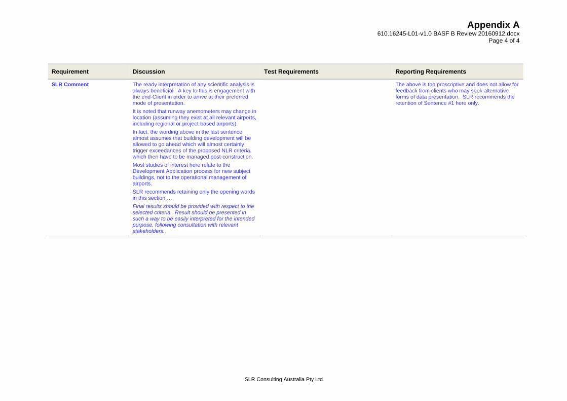
Results Final results should be provided with respect to the selected criteria. Result should be presented in such a way to be easily interpreted for the intended purpose which is generally direct comparison with airport operation wind speed limits. CPP has found this is most effectively achieved by analysing the results to determine the runway anemometer wind speed required to reach the criterion threshold. This result can be compared directly with operational wind speed limits. If any reported values reach the criterion level for a wind speed were the airport intend to have the runway operating, then the subject structure may impact operations
The consultant’s report should include test results for all test locations and a discussion of the results. It is recommended results are presented as the wind speed at the airport anemometer required to reach the criteria threshold for both wind shear and turbulence. An example illustration of results is given in Figure 5.
Appendix A 610.16245-L01-v1.0 BASF B Review 20160912.docx
Page 4 of 4
SLR Consulting Australia Pty Ltd
Requirement Discussion Test Requirements Reporting Requirements
SLR Comment The ready interpretation of any scientific analysis is always beneficial. A key to this is engagement with the end-Client in order to arrive at their preferred mode of presentation.
It is noted that runway anemometers may change in location (assuming they exist at all relevant airports, including regional or project-based airports).
In fact, the wording above in the last sentence almost assumes that building development will be allowed to go ahead which will almost certainly trigger exceedances of the proposed NLR criteria, which then have to be managed post-construction.
Most studies of interest here relate to the Development Application process for new subject buildings, not to the operational management of airports.
SLR recommends retaining only the opening words in this section …
Final results should be provided with respect to the selected criteria. Result should be presented in such a way to be easily interpreted for the intended purpose, following consultation with relevant stakeholders.
The above is too proscriptive and does not allow for feedback from clients who may seek alternative forms of data presentation. SLR recommends the retention of Sentence #1 here only.

Appendix B 610.16245-L01-v1.0 BASF B Review 20160912.docx
Page 1 of 5
SLR Comments on CPP Report Table 5 Requirements for CFD Based Modelling Studies
SLR Consulting Australia Pty Ltd
Requirement Discussion Test Requirements Reporting Requirements
Model Geometry The starting point for the computation model design is the input geometry.
As per wind tunnel test requirements with the exception that there is no requirement to scale the geometry
The Consultant’s report should include a plan view drawing and 3-D views of the CFD geometry including modelled surrounding area.
SLR Comment Small building features are better modelled in CFD versus the wind tunnel, where model buildings are typically built to a scale of around 1:500 or more. This may be important when assessing the benefit of porous screens other façade or roof appendages designed to mitigate adverse wind conditions.
The CFD model should include all building details that are likely to have a potentially significant impact on the influence which the subject building(s) may have on the downstream wind environment of interest (ie in a vertical plane along the runway centreline).
Agreed.
CFD Solver The CFD simulations should be performed on a high end validated commercial CFD solver. Typical examples include various solvers provided by Ansys and CD-Adapco. Non-commercial or custom solver software can be used if accompanied by relevant validation material and/or references to peer reviewed validation material.
The Consultant’s report should specify the solver software used.
SLR Comment Agreed Agreed
Atmospheric Boundary Layer Classification
The required characteristics for the simulated atmospheric boundary layer are the same as listed for the equivalent wind tunnel test. The challenges in achieving a suitable setup however are quite different and this is one the more common sources of error or incorrect modelling assumptions in computational wind engineering type studies, especially in regard to correct prorogation of the input boundary layer through the computation domain. It is therefore crucial that any airport turbulence study performed using CFD clearly demonstrates that a suitable simulation environment was achieved.
As per wind tunnel test. Special attention should be given to ensuring as suitable and stable boundary Layer in terms of velocity distribution, turbulence intensity distribution and distribution of turbulence scales is provided at the start of the modelled area (where building and structures are represented geometrically).
The consultant’s report should include a brief description of the chosen ABL classification/s and calibration procedure. Graphical illustration must be provided showing the measured profiles relative to the target profiles for vertical velocity and turbulence intensity at the start of the modelled area, and spectral distribution of turbulence at or near building/structure height. Data should be provided demonstrating suitable ABL propagation through the domain and across open airport space where relevant.
SLR Comment Agreed Agreed Suggested wording change to Sentences #2 & #3
Data should be provided demonstrating suitable ABL propagation through the domain and across open airport space where relevant, including vertical profiles of velocity and turbulence intensity.

Appendix B 610.16245-L01-v1.0 BASF B Review 20160912.docx
Page 2 of 5
SLR Consulting Australia Pty Ltd
Requirement Discussion Test Requirements Reporting Requirements
Turbulence Modelling In order to capture the time varying effect of turbulence a transient form of CFD simulation must be used. The simulations should be run using settings suitable to sufficiently resolve and measure velocity fluctuations of 1-2s duration. A turbulence model shall be used in the simulation that is of the scale resolving type (e.g LES, SAS). If zonal methods are used (e.g. zonal LES), then they must be scale resolving in a minimum volume that surrounds the subject building and downstream in the building wake extending to, and surrounding, the runway measurement area.
The consultant’s report should include a description of the numerical setup used including the chosen turbulence model and temporal settings. Wherever the simulation has been designed to model or capture turbulence differently in different areas of the modelled area e.g. less advanced techniques or resolution in non-critical areas of domain, then the areas were valid results can be measured must be clearly marked.
SLR Comment Hybrid model such as D-LES can be used to carry out the necessary CFD modelling in a timely manner, but which nevertheless captures relevant turbulence characteristics. D-LES combines the benefits of RANS and LES: while RANS can achieve good prediction for attached boundary layers, LES can capture unsteady motions of large eddies in separated regions. All SRS methods including D-LES require time-resolved simulations with relatively small time steps.
Agreed
Computational Grid The type, quality and size of the computation mesh used to discretize the fluid volume is critical to any CFD model and particularly when turbulence scales are being simulated and measured.
A computational mesh should be designed that is of high quality and suitable to be used in combination with the chosen CFD solver and turbulence modelling approach. The mesh density shall be sufficient to model turbulence scales equivalent to 1-2 seconds gusts in a minimum volume which surrounds the subject building and extends downstream to encompass the full measurement area of the runway.
The consultant’s report should include a description of the meshing approach used. Images of the mesh should be included that illustrate the quality and resolution in the significant areas of the domain.
SLR Comment A mesh sensitivity analysis is recommended for inclusion in the consultant’s report to ensure that all relevant turbulence scales are modelled.
Statistical Settings The transient simulation will be sampled in order to calculate statistical quantities such as mean velocity and standard deviation values. It is important that the solution sufficient length of time to obtain converged and stable statistical quantities.
A total sample length should be used of sufficient length to achieve stable statistical averaging when considering the largest turbulent length scales simulated in the domain.
The consultant’s report should specify the sample time used for statistical values and comment or demonstrate how this was determined to be sufficient.
SLR Comment Agreed Agreed Agreed
Appendix B 610.16245-L01-v1.0 BASF B Review 20160912.docx
Page 3 of 5
SLR Consulting Australia Pty Ltd
Requirement Discussion Test Requirements Reporting Requirements
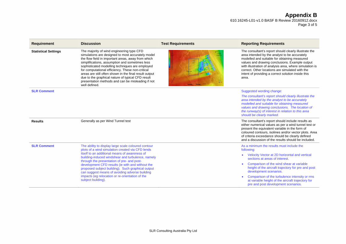
Statistical Settings The majority of wind engineering type CFD simulations are designed to most accurately model the flow field in important areas, away from which simplifications, assumption and sometimes less sophisticated modelling techniques are employed for computational efficiency. These non-critical areas are still often shown in the final result output due to the graphical nature of typical CFD result presentation methods and can be misleading if not well defined.
The consultant’s report should clearly illustrate the area intended by the analyst to be accurately modelled and suitable for obtaining measured values and drawing conclusions. Example output with illustration of analysis area, where simulation is correct. Other locations are simulated with the intent of providing a correct solution inside this area.
SLR Comment Suggested wording change:
The consultant’s report should clearly illustrate the area intended by the analyst to be accurately modelled and suitable for obtaining measured values and drawing conclusions. The location of the runway(s) of interest in relation to this area should be clearly marked.
Results Generally as per Wind Tunnel test The consultant’s report should include results as either numerical values as per a wind tunnel test or present the equivalent variable in the form of coloured contours, isolines and/or vector plots. Area of criteria exceedance should be clearly defined and a discussion of the results should be included.
SLR Comment The ability to display large scale coloured contour plots of a wind simulation created via CFD lends itself to an additional means of awareness of building-induced windshear and turbulence, namely through the presentation of pre- and post-development CFD results (ie with and without the proposed subject building). Such graphical output can suggest means of avoiding adverse building impacts (eg relocation or re-orientation of the subject building).
As a minimum the results must include the following:
Velocity Vector at 2D horizontal and vertical sections at areas of interest.
Comparison of the wind shear at variable height of the aircraft trajectory for pre and post development scenarios.
Comparison of the turbulence intensity or rms at variable height of the aircraft trajectory for pre and post development scenarios.

Appendix B 610.16245-L01-v1.0 BASF B Review 20160912.docx
Page 4 of 5
SLR Consulting Australia Pty Ltd
Requirement Discussion Test Requirements Reporting Requirements
Benchmarking and Validation
There is a large number of variables describing the numerical setup of CFD models, many of which can heavily affect the final output. Unlike physical simulations, computation fluid simulation can easily produce results that are not physically possible if an incorrect approach is used. Use of CFD for detailed modelling of turbulence in the natural wind environment is complex and not yet considered an established commercial practise for many types of quantitative studies. Given the nature of wind turbulence studies at airports is critical that any approach adopted by an organisation for this form of modelling be validated through benchmarking studies, unless it is intended to also undertake physical experiment for the site e.g. the CFD is being used as a screening study and wind tunnel studies will be used later to quantity the final design.
A comparison study should be undertaken to develop and validate the specific CFD approach used within an organisation for airport wind shear and turbulence assessments. This study should benchmark the CFD output against some form of equivalent physical measurement at model scale in a wind tunnel, or full scale in the field. The CFD validation model should have similarity with the subject CFD simulation in terms of computation domain size, boundary condition types, boundary input profile and propagation strategy, mesh density and type, meshing strategy, time step resolution, turbulence models, numerical discretion schemes and contain geometry that is relevant to an airport wind shear type study.
The consultant’s report should include an appendix containing a brief summary of relevant validation studies and present relevant comparative benchmarking data between simulation and experiment.
SLR Comment It is true that Wind Engineering practice has been (globally) well established and relatively unchanged for many years.
CFD practice however has undergone and is continuing to undergo rapid development, primarily due to the exponential growth of computational power.
SLR therefore agrees that a consultant choosing a CFD-based methodology for airport building related studies needs to demonstrate their understanding of the complexities of CFD simulations and an awareness of recent studies both within academia and consultancy.
A considerable number of CFD publications for the assessment of turbulence and wind-induced impacts has been published in relevant learned (refereed) journals (eg Journal of Wind Engineering & Industrial Aerodynamics) especially in the past decade.
There are also now International Standards, eg the Netherland NEN 8100 (2006) Wind Comfort and Wind Danger in the Built Environment, which allow a proponent the option of choosing between wind-tunnel modelling or CFD to assess local urban design related impacts in relation to wind. This particular standard has also led to the specification of quality assurance requirements, both for CFD and for wind-tunnel testing – refer below references.
Numerous technical papers (within refereed journals) have investigated wind engineering applications for CFD and led to the development of best practice guidelines.
The reader is referred to the brief listing below of a representative sample of the literature in relation to CFD Best Practice.
Accordingly, SLR believes the Reporting requirement here should be …
The Consultant’s report should include a discussion of relevant validation and benchmarking studies providing sufficient confidence to the reader that the level of sophistication used with the CFD modelling is appropriate for the requirements of reliably capturing airport building windshear and turbulence impacts.

Appendix B 610.16245-L01-v1.0 BASF B Review 20160912.docx
Page 5 of 5
SLR Consulting Australia Pty Ltd
Requirement Discussion Test Requirements Reporting Requirements
CFD References NEN, 2006. Wind Comfort and Wind Danger in the Built Environment, NEN 8100, Dutch Standard, 2006.
NEN 2006. Application of mean hourly wind speed statistics for the Netherlands, NPR 6097:2006 (in Dutch). Dutch Practice Guideline.
Willemsen E, Wisse JA. 2007. Design for wind comfort in The Netherlands: Procedures, criteria and open research issues. J Wind Eng Ind Aerodyn 95(9-11):1541-1550.
Blocken B, Carmeliet J, Stathopoulos T. 2007. CFD evaluation of the wind speed conditions in passages between buildings – effect of wall-function roughness modifications on the atmospheric boundary layer flow. J Wind Eng Ind Aerodyn 95(9-11):941-962.
Blocken B, Janssen WD, van Hooff T. 2012. CFD simulation for pedestrian wind comfort and wind safety in urban areas: General decision framework and case study for the Eindhoven University campus. Environ Modell Softw 30:15-34.
Blocken B, Stathopoulos T, Carmeliet J. 2007. CFD simulation of the atmospheric boundary layer: wall function problems. Atmos Environ 41:238-52.
Franke J, Hellsten A, Schlünzen H, Carissimo B. 2007. Best practice guideline for the CFD simulation of flows in the urban environment. COST Action 732: Quality Assurance and Improvement of Microscale Meteorological Models.
Franke, J., Hellsten, A., Schlünzen, H., Carissimo, B., 2011. The COST 732 best practice guideline for CFD simulation of flows in the urban environment – A summary. Int J Environ Pollut 44(1-4):419-427.
Franke J, Hirsch C, Jensen AG, Krüs HW, Schatzmann M, Westbury PS, Miles SD, Wisse JA, Wright NG. 2004. Recommendations on the use of CFD in wind engineering. Proc. Int. Conf. Urban Wind Engineering and Building Aerodynamics, (Ed. van Beeck JPAJ), COST Action C14, Impact of Wind and Storm on City Life Built Environment, von Karman Institute, Sint-Genesius-Rode, Belgium, 5 - 7 May 2004.
Gorlé C, van Beeck J, Rambaud P, Van Tendeloo G. 2009. CFD modelling of small particle dispersion: the influence of the turbulence kinetic energy in the atmospheric boundary layer. Atmos Environ 43(3):673-681.
Hargreaves DM, Wright NG. 2007. On the use of the k–_ model in commercial CFD software to model the neutral atmospheric boundary layer. J Wind Eng Ind Aerodyn 95(5):355-369.
Mochida A, Tominaga Y, Murakami S, Yoshie R, Ishihara T, Ooka R. 2002. Comparison of various k–e models and DSM applied to flow around a high-rise building—report on AIJ cooperative project for CFD prediction of wind environment. Wind Struct. 5(2–4):227–244.
Tominaga, Y., Mochida, A., Yoshie, R., Kataoka, H., Nozu, T., Yoshikawa, M., Shirasawa, T. 2008. AIJ guidelines for practical applications of CFD to pedestrian wind environment around buildings. J Wind Eng Ind Aerodyn 96(10-11):1749-1761.
Tominaga Y, Mochida A, Murakami S, Sawaki S. 2008. Comparison of various revised k- models and LES applied to flow around a high-rise building model with 1:1:2 shape placed within the surface boundary layer. J Wind Eng Ind Aerodyn 96(4):389-411.
Yang Y, Gu M, Chen S, Jin X. 2009. New inflow boundary conditions for modelling the neutral equilibrium atmospheric boundary layer in computational wind engineering. J Wind Eng Ind Aerodyn 97(2):88-95.
Yoshie R, Mochida A, Tominaga Y, Kataoka H, Harimoto K, Nozu T, Shirasawa T. 2007. Cooperative project for CFD prediction of pedestrian wind environment in the Architectural Institute of Japan. J Wind Eng Ind Aerodyn 95(9-11):1551-1578.