1 signal processing for temporal spectrum sharing in a ... · signal processing for temporal...
TRANSCRIPT

1
Signal Processing for Temporal Spectrum Sharing ina Multi-radar Environment
Francisco Paisana, Nicholas Kaminski, Nicola Marchetti and Luiz DaSilvaCONNECT, Trinity College Dublin, Ireland
Email: {paisanaf, kaminskn, marchetn, dasilval}@tcd.ie
Abstract—Regulators, aware of the significant underutilizationof spectrum reserved for radar operation, are starting to openthese bands for sharing with commercial services. In this paper,we provide the signal processing techniques necessary to applytemporal sharing to reduce radar exclusion zones and increasespectral efficiency. Our approach directly extends to the fairlycommon scenario of multiple radars operating at relatively closedistance in the same frequency and allows a secondary user totransmit without exceeding a stipulated level of interference atany radar. We require only that radars behave periodically; oursecondary users apply adaptive sensing to track radar behaviorin real-time without a priori information. To accomplish this, weintroduce a pulse deinterleaving mechanism to separate multipleradar emissions in real-time, with no batch or offline processing.We show that our approach to temporal sharing is applicable tostatic or low mobility sharing scenarios, where the interferencechannel displays quasi-periodic features.
Keywords—Temporal Sharing, Radar Bands, Spectrum Sharing,Dynamic Spectrum Access, Software-defined Radio
I. INTRODUCTION
Over 2.4 GHz of the US spectrum between 225 MHzand 6 GHz is currently allocated to radar-reliant services,such as radio-location, weather forecast, and radio-navigation.However, several measurement studies show that these servicesdo not fully utilize the bandwidth, time, and space associatedwith this allocation [1]. Due to the high cost and time thatit takes to replace legacy radar infrastructure, regulators havebeen incentivising spectrum sharing initiatives in detriment ofmore conventional frequency relocations. The Federal Commu-nications Commission (FCC) proposal for small cell and radarcoexistence in the 3.5 GHz band [2] and the global allowanceof Wireless Local Area Network (WLAN) devices in the 5GHz band exemplify this trend.
The Spectrum Access System (SAS) and Dynamic Fre-quency Selection (DFS) techniques for 3.5 GHz and 5 GHzbands currently dominate proposals for shared spectrum ac-cess in radar bands [2], [3]. Both of these techniques relyon exclusion zones, centered on incumbents, to demarcatethe maximum coverage of radar transceivers. However, suchspatial sharing schemes block access to radar bands for thelarge percentage of the world population in range of coastalregions and airports [1].
Several efficient spectrum sharing approaches based onfrequency separation [4] or precoding [5] have been proposedunder the DARPA Shared Spectrum Access for Radar andCommunications (SSPARC) program for coexistence between
communication and radar systems. However, considering thespecific focus of this program, these works are better targetedat more modern military radar systems with low out-of-band emissions, which often employ frequency hopping andmultiple adaptive antennas. Legacy systems with high out-of-band emissions and mechanically rotating antennas stillconstitute the majority in radar bands, and, considering theirhigh price and low cost of operation, replacing them for moreadvanced technologies may take several decades to complete[6]. Furthermore, given the unique advantages of each genera-tion of radar technology and the fact that digital data from radarsites can be combined for better performance, operators are inmany cases following a strategy of complementing their oldinfrastruture with newer systems, rather than replacing it [6]–[8]. The expected high longevity of legacy radar systems, incombination with the fact they currently constitute a bottleneckboth in terms of required exclusion zones and frequencyseparation [3], [6], [9], leads us to focus, in this paper, ontheir coexistence with communication systems.
Consideration of the temporal dynamics of radar systemswith highly directional rotating antennas can enable a moreefficient approach to spectrum sharing. Significant spectrumopportunities exist for Secondary Users (SUs) to transmitinside areas currently designated as exclusion zones, providedthat they do so only when radar antennas are pointing in an-other direction [10], [11]. This paper addresses the challengesand techniques necessary to realize such temporal sharing.In particular, we focus on the signal processing techniquesrequired to enable temporal sharing for the large portion ofradars that employ the same antenna for transmission andreception, display periodic scan patterns, and do not performLow-Probability-of-Intercept (LPI) techniques [6]. Examplesof such systems include the ARSR and FPS series radars in theL band, ASR in the lower S band, and maritime (magnetron orsolid-state) in the upper S band [6]. Note, however, that theseconditions may not be found in some tracking, ElectronicallySteered Array (ESA) and frequency hopping systems. Astemporal sharing is unable to accommodate such incumbents,we do not advocate its use as a standalone technique, butrather as an extension of other more conservative spectrumaccess schemes to which SUs fall back when facing morechallenging sharing conditions. Such a multi-strategy approachto sharing, illustrated in Figure 1, can be accomplished withthe assistance of a context-aware database or SAS to determineover which policy contexts, locations and bands both spatialand temporal sharing, or any other scheme are applicable. This

2
No sharing, e.g. within exclusion zone,
emergency situations
Spatial sharing, e.g. LPI, classified
waveform, ESA, non-periodic scan radarSAS
Incumbents ESC Public
Policy
Temporal Sharing, e.g. periodic
mechanically steering radarsAccess rules and
thresholds
commercial
military
Requests for spectrum
access
Modes of Spectrum AccessSecondary Users context awareness
Fig. 1: Proposed framework for database-aided sharing.
database could obtain this information through coordinationwith the incumbents, which would be straightforward forsystems whose parameters and positions are already updatedin databases and websites in real-time (e.g. weather [12], [13],traffic control, radionavigation), or via Environmental SensingCapability (ESC), as it is currently envisioned in the 3.5 GHzband [9].
A. Our ContributionWe distinguish the technical challenges in the deployment
of opportunistic temporal sharing into the two sub-problemsof radar signal deinterleaving, and interruption period pre-diction. Radar signal deinterleaving enables SUs to share aspectrum band with multiple radars by empowering the SUto differentiate and separate superimposed signals of differenttransmitters. This deinterleaving depends on a radar’s signalhaving at least one feature, such as Pulse Width (PW), fre-quency, or Pulse Repetition Interval (PRI), that is unique withregard to the remaining signals. Fortunately, such uniquenessis generally a reasonable assumption, considering that radarsystems need to display different features to operate close toeach other. For instance, low duty cycle suppression techniquesincrease a radar system’s tolerable Interference to Noise Ratio(INR) level from -6 dB to +63 dB, when the interferenceis caused by another radar with a different PRI [14]. Theinterruption period prediction process enables SUs to discernperiodic features in radars’ antenna sweeping motions, andderive the resulting temporal spectrum opportunities.
Prior to our use for spectrum sharing, radar signal dein-terleaving was originally explored in Electronic Intelligence(ELINT) to add in the interception and analysis of radaremissions to detect and identify potential enemy systems.As such, we note some differences when using the conceptfor temporal sharing. First, our purpose is the separation ofsignals with power large enough for the generating transmitterto be considered within interference range over the band ofoperation of the SU, rather than the classification of all systemsin a certain area. Second, tracking the dynamic operation ofmultiple radars to support temporal sharing requires an onlinedesign for the deinterleaving algorithm.
Interruption period prediction comprises the two sub-problems of scan analysis and scan tracking. Scan analysisestimates the Antenna Scan Period (ASP) and radiation patternfeatures of each of the detected and deinterleaved radars withininterference range. Scan tracking schedules occasional sensingto maintain synchronization with the radar systems’ rotation
phases and identify changes in the radio environment througha recursive update scheme.
The main contributions of this paper are:• an SU architecture for temporal sharing that addresses
both the radar signal deinterleaving and interruptionperiod prediction problems. Our proposed architectureincorporates lessons learned from our implementation oftemporal sharing in Software Defined Radio (SDR) [15].
• a non-coherent radar signal detection and feature estima-tion and representation scheme.
• a Time Of Arrival (TOA) radar deinterleaving method thatoperates in an online manner.
• a temporal sharing spectrum opportunity predictionscheme based on scan period and radiation pattern es-timation.
• a scan tracking scheme that detects and compensatesfor changes in the radio environment, including smalldrifts in the radar antenna rotation or changing channelcharacteristics.
B. Related WorksSeveral works have been published assessing the required
interference protection of radar and communication systemswhen coexisting in the same band. The National Telecommu-nications and Information Administration (NTIA) has releasedseveral reports sheding some light on the effects of interferenceon radar receivers [14], [16], and required exclusion zone sizesin the 3.5 GHz band [9]. In [17], [18], the authors analysedhow radar transmission parameters, namely power, duty cycleand Pulse Repetition Frequency (PRF) may disrupt currentcommunication systems’ throughput and packet transmissiondelays. Other works, such as [10], [19], focused on the impactof the aggregation of interference from multiple SUs on radarreceivers.
The inefficiencies inherent in spatial sharing have led toan increased interest on more cooperative spectrum sharingapproaches for the radar bands. The DARPA SSPARC programexemplifies one such initiative, seeking the development oftechnology for coexistence between military radars and othermilitary or commercial systems [20]. Under this program,the authors in [21] focus on the coexistence between radarand communication systems from an information theoreticalperspective, developing metrics that account for the impactof interference on the co-design of radar and communicationsystems. In [4], the authors study the spectral efficiency gainsprovided by frequency separation techniques coordinated by acontext-aware SAS, with military operation security in mind.The authors in [5], [22]–[24] analysed the capability of MIMOmilitary radars at avoiding harmful interference with cellularsystems in the 3.5 GHz band by virtue of adaptive antennas.
Focusing on spectrum sharing techniques for the large por-tion of radar systems that rely on rotating antennas and do notemploy LPI techniques, our preliminary works in [13], [25],[26] and other authors in [11], [12] analysed the efficiencygains provided by coexistence mechanisms, such as temporalsharing and beamforming. In [12], [25], [26], in particular,it is proposed the use of a context-aware SAS that utilizes

3
TABLE I: Table of key notations used throughout this work
Notation DescriptionNradar Number of radar systems in an SU’s surroundingsfci Centre frequency of radar if0 SU’s sampling rate
Wav
efor
m
tTOAi,m TOA of the pulse m of radar i
T PRIi,m PRI of radar i at pulse index m
APAi,m Amplitude of the pulse m of radar i
fPFi,m Centre frequency of pulse m of radar i at the SU’s baseband
T PWi,m Width of pulse m of radar i
ΞPDWi,m
Vector containing the Pulse Description Words (PDWs), i.e. parameters describing anintercepted pulse m of radar i
ΞPTi Vector of parameters describing a pulse train emitted by a radar i
Lin
kB
udge
t
P radar,Txi
Transmit power of radar with index i
P SU,Tx Transmit power of SUGPUi (t) Antenna gain of radar i in the direction of the SU at instant of time t
Gi,max Maximum antenna gain of a radar i
GSUi Antenna gain of the SU in the direction of radar i
FDRradar-SUi
Frequency Dependent Rejection, i.e., attenuation of the radar’s signal caused bythe SU’s receiver chain
FDRSU-radari Attenuation of the SU’s signal caused by the radar’s Receiver (Rx) chain
Lradar-SUi Attenuation of radar’s signal due to channel effects (e.g. fading, path loss)
LSU-radari Attenuation of the SU’s signal caused by channel effects
λi(t) Received power by the SU from radar i over timeISU-radari (t) Received power by the radar i from the SU over time
Scan
Patte
rn
TASPi The time necessary for the radar antenna to make a full sweep; period of λi(t).
ΛPARPi (θ)
Perceived Antenna Radiation Pattern, i.e. shape of the repeated pattern within λi(t),where θ ∈ [0, 2π] corresponds to the radar antenna rotation phase.
Tλ,refi,n
Reference timestamp at which the phase θ = 0◦ of ΛPARPi (θ) occurs
Θi,k Phase Interval at which ΛPARPi (θ) crosses γthres
NΘi Number of phase intervals Θi,k for radar i where ΛPARP
i (θ) crosses γthres
∆IPi,k,m
Interruption period for a single radar i-SU pair derived from the phase interval Θi,kfor the antenna scan index m
σPARPΛ
Standard deviation of a radar’s instantaneous PARP over its reference time,due to channel decoherence
Ξscani
Set of scan parameters involved in the computation of ∆IPi,k,m . We represent this set
as a vector [TASPi , T
λ,refi,n
,Θi,1, ...,Θi,NΘi
].
Thr
esho
lds
Imax Maximum interference a radar may receive from SUs without service disruptionγthres Sensing threshold used by the SU to decide whether to interrupt its transmissions
γpulseThreshold based on which the SU’s sensing module decides whether it has detecteda radar pulse or just noise
γR Threshold based on which the SU decides whether to terminate the sensing session
γCThreshold used to decide whether a pulse belongs to a clusteringduring the pulse sorting stage
γPRI Threshold used during TOA deinterleaving
incumbents’ information to select and configure SUs’ sensingor coexistence mechanisms, and to dynamically account forthe impact of aggregate interference. However, these works arelimited to the design of the SAS architecture or quantificationof spectral efficiency gains, without addressing the challengesand signal processing techniques necessary to realize suchcoexistence mechanisms. Furthermore, schemes like the onein [12] that do not rely on sensing information do not accountfor the impact of reflections on interference.
II. RADAR SIGNAL MODEL
To construct our model, we imagine a single SU at a fixedposition receiving signals from Nradar radar systems in itssurroundings. Each individual radar i ∈ {1, ..., Nradar} emits aPulse Train (PT) with a different peak transmit power P radar,Tx
iand center frequency f ci , using a directive antenna that rotatesmechanically in azimuth with period TASP
i . From this SU’spoint of view, the received signal from each radar can becharacterized as a waveform or a scan pattern. A waveformrepresents the received PTs as a set of modulation features,such as PRF or PRI, PW, f c, and Intra-Pulse Modulation(IPM). Alternatively, a scan pattern captures the variationin amplitude of a PT over time, which results from thedirectionality and rotation of the emitter’s antenna.
A. Waveform ModelWe model samples received by an SU from a single radar i
in an ideal channel as follows
xi[n] =
+∞∑m=−∞
APAi,m.pi[n−mT PRI
i,m].e2πjnfPFi,m/f0 (1)
Here, n is the sample index and m is the pulse index. The pulseshape pi[·] defines the IPM and PW, and, to reduce the poweramplifier complexity, usually displays constant envelope. Notethat multipath may disperse the pulse shape.
We collect the features of the signal into vectors of PDWsΞPDWi,m = [tTOA
i,m , TPWi,m, f
PFi,m, A
PAi,m]T. For the case of radar sys-
tems with fixed PW, Pulse Frequency (PF) and PRI, T PWi,m
and fPFi,m will be constant with m and tTOA
i,m values follow thesequence
tTOAi,m = tTOA
i,j + (m− j)T PRIi ,∀j,m ∈ Z (2)
As a result, we characterize an entire PT with ΞPTi =
[tTOA,refi , T PW
i , fPFi , T
PRIi ]T, where tTOA,ref
i corresponds to a ref-erence pulse’s TOA from which other TOA may be derivedwith equation (2). Note that we do not consider the APA hereas it is the focus of the scan pattern model.
B. Scan Pattern ModelThe variation in power over time of the pulses received
by the SU from a single radar system can be modelled as acurve in dBW λi(t), which is obtained through the link budgetequation,
λi(t) = P radar,Txi +GPU
i (t)+GSUi −FDRradar-SU
i −Lradar-SUi (3)
The interference caused by a single SU on a radar can, in turn,be defined as follows,
ISU-radari (t) = P SU,Tx +GPU
i (t) +GSUi − FDRSU-radar
i −LSU-radari
(4)Considering that both the radar and SU reuse the sameantennas and frequency bands for Transmitter (Tx) and Rx,the channel effects are reciprocal (LSU-radar = Lradar-SU) [1], [3],[27]. The same assumption cannot be made for the FrequencyDependent Rejection (FDR), as the radars and SU employtransceivers with different spectrum masks and that may beuncalibrated.
To ensure that the interference at the radar does not surpassa specified level ISU-radar
i (t) < Imax, the SU cannot transmitwhenever λi(t) is above the threshold γthres, which can bederived by subtracting equations (3) and (4) as follows,
γthres = P radar,Txi − FDRradar-SU
i + Imax − P SU,Txi + FDRSU-radar
i .(5)
We define an interference period (∆IP) as a time intervalwhere we have λ(t) ≥ γthres ∀t ∈ ∆IP. Additionally, weconsider a radar system r to be within interference range ofan SU if the peak value of λr(t) for the SU is above γthres.
As can be seen from (5), γthres is dimensioned based onterms which are not known locally by SUs and change fromradar to radar. Furthermore, as the condition λi(t) < γthres

4
t
i(t)
iPARP()λi
max
i,1i,0
2
thres
i,3i,2i,1i,0
thres
Fig. 2: Characterization of a radar periodic scan pattern.
for SU transmissions does not account for the aggregation ofinterference from multiple SUs, a safety margin has also tobe subtracted from γthres. To account for all these factors, weargue that it should be the role of the SAS to set γthres andinform SUs of its value. The SAS may set a unique, constantγthres value following a worst scenario approach, change γthresaccording to the SU’s location or based on interference reportsfrom incumbents, or set different γthres values for different ΞPT
the SU may detect. We consider out of the scope of this paperto evaluate different mechanisms the SAS may use to computeγthres.
From (5), it is apparent that γthres, for a single SU case,is constant in time and does not depend on the instantaneousradar antenna gain or orientation. In particular, the thresholddoes not depend on whether the radar antenna tilt is alignedwith the SU or which radiation lobe illuminates the SU at agiven instant of time.
C. Periodic Scan Pattern ModelWhen radar systems exhibit periodic scan patterns and fixed
propagation conditions, the λi(t) curve can be fully character-ized by the features TASP
i , ΛPARPi (t) and Tλ,ref
i,n , described inTable I and illustrated in Figure 2.
For a given time t, the instantaneous rotation phase can bederived through the following transformation
θ(t) = 2π
(t− Tλ,ref
i,n
TASPi
−
⌊t− Tλ,ref
i,n
TASPi
⌋)(6)
In turn, we obtain λi(t) through ΛPARPi (θ(t)). Based on phase
intervals Θi,k, k ∈ {1, ..., NΘi }, we derive the interruption
periods (∆IPi,k,m|n) for a single radar-SU pair and for any
antenna scan index m ∈ N as follows
∆IPi,k,m|n =
TASPi
2πΘi,k + Tλ,ref
i,n + (m− n)TASPi (7)
D. Multipath EffectsMultipath may significantly affect the shape of ΛPARP
i (θ),distancing it from the real radar antenna radiation pattern. Tocorroborate this claim, we illustrate in Figure 3 two represen-tative examples of the λ(t) curves, one in LOS and the otherin NLOS, we collected during our measurement campaign inCork naval base, Ireland [28]. As can be seen in Figure 3a,the illumination instances of our spectrum analyser by theradar antenna main-beam under LOS are evident, displaying asignal strength approximately 25 dB higher than the instancesthat result either from reflections or the illumination by side-lobes. In contrast, under NLOS conditions, the effect of clutter
becomes non-negligible, and the ΛPARPi (θ) is significantly less
sparse. As a consequence, there will be, in the latter case,a higher number of interruption phase intervals NΘ
i , and theSU will need to interrupt its transmissions more frequently toavoid causing interference.
(a) LOS environment.
(b) NLOS environment.
Fig. 3: Measured λ(t) curves at different fixed locations for amagnetron radar. Each blue circle corresponds to a detected pulsewith a specific TOA and PA.
As shown in Figure 3, in scenarios of low or no mobility,reflection paths maintain a constant relative attenuation andangle of arrival, and the λ(t) curves display an approximatelyperiodic pattern. In the high mobility case, not shown in thispaper for brevity, we observed that the periodicity of λi(t)would be lost, and the ΛPARP
i (θ) would gradually change overtime. The nature and rate of this variation were particularlycorrelated to the speed of the link terminals, and the spatialcorrelation of their channel fading.
Based on such observations, we decided to separate the timeseries ΛPARP
i (θ; t) into a static term, a stationary stochastic, andtrend stochastic processes as follows,
ΛPARPi (θ; t) = ΛPARP
i (θ; t0) + Zi(t) + Ui(t) (8)
Here ΛPARPi (θ; t0) is a reference Perceived Antenna Radiation
Pattern (PARP) for time t0. Zi(t), and Ui(t) represent thechannel decoherence processes. To the best of our knowledge,there are no propagation studies on modelling the processesZi(t) and Ui(t) for radar spectrum sharing. As full analysisof Zi(t) and Ui(t) is out of scope here, we focus on thequasi-static radar-SU scenario, where Ui(t) is negligible andZi(t) is modelled through a discrete white noise stochastic pro-cess Zi,0, Zi,1, ..., Zi,n with distribution N (0, σPARP
Λ ), whereZi(t = mτ) = Zi,m, and τ is the decoherence time.

5
III. TEMPORAL SHARING DESIGN
Temporal sharing relies on a Quiet Period (QP) allocationscheme that maximizes the SU’s throughput under the con-straint of limiting the interference at any of the neighbourNradar radar systems to be below the stipulated limit Imax dBW.With SQP as the set of all scheduled QPs, we state this as
∆IPi,k,m ⊆ SQP ∀i ∈ {1, ..., Nradar}, k ∈ {1, ..., NΘ
i },m ∈ N(9)
Each QP in SQP results from one or the union of multipleintersecting expected interruption periods ∆IP
i,k,m that the SUcomputes through equation (7). Naturally, uncertainties, suchas noise, channel decoherence, and multiple radars’ interfer-ence will make ∆IP
i,k,m 6= ∆IPi,k,m. Therefore, the probabilities
of interruption misdetection and false alarm can be expressedas,
P IPMD = P (t /∈ ∆IP
i,k,m|t ∈ ∆IPi,k,m) (10)
P IPFA = P (t /∈ ∆IP
i,k,m|t ∈ ∆IPi,k,m) (11)
Here, we propose a temporal sharing architecture that supportsthe joint minimization of these two probabilities.
A. Proposed SU ArchitectureIn figure 4, we illustrate our SU system architecture, which
is formed by the three main sub-modules: controller, reasoningengine, and spectrum monitoring system.
1) controller: The controller interfaces with the SAS, fromwhich the controller obtains policy and context-aware spec-ifications, such as γthres, Tsensing,min, available channels, andauthorization to perform temporal sharing. The controller con-figures the other sub-modules on the basis of this information.
2) reasoning engine: The reasoning engine is conceptuallydivided into the sub-modules: modeling system, and temporalsharing manager. The modeling system gathers and processesthe spectrum occupancy reports coming from the spectrummonitoring system and constructs a representation of the SU’sradio environment, which we call an RF snapshot. An RFsnapshot contains information on the number of radar systems,Nradar, as well as their estimated waveform and scan featuresΞPTi , and Ξscan
i . The temporal sharing manager utilizes theinformation stored in the current RF snapshot to infer the∆IP intervals based on (7), which it then uses to schedulefuture QPs. It also coordinates the activation of the spectrummonitoring system in order to update the current RF snapshot.
3) spectrum monitoring system: The spectrum monitoringsystem comprises all the signal processing stages needed todetect, separate, and characterize the radar systems withininterference range. Measured and processed radio environmentdata is then represented as a spectrum occupancy report overthe time period specified by the reasoning engine’s activationcommand.
We divide the processing of the SU’s received samples intothree different tasks: pulse detection and PDW estimation,pulse sorting, and scan analysis. In the first task, the spectrummonitoring system estimates PDW sets (ΞPDW) for pulses ofintercepted radar signals. Pulse sorting then follows, which
Fig. 4: Proposed architecture for an SU’s temporal sharing cognitiveengine, and its interactions with remaining components, namely SAS,radio front-end, and RAT.
SU
’s
Re
ceiv
ed
Po
we
r
Sensing Event
scheduled
New RF
snapshotRF
snapshot
update
�thres
Tx/Rx
mode
Sensing Mode
QP / Tracking
ModeLoss of synch
Fig. 5: Illustration of the SU’s behavior after losing synchronizationwith a radar rotation.
clusters the detected pulses based on their ΞPDW into distinctPTs with feature sets ΞPT
i and generates a λi(t) for each PT.Scan analysis then estimates the incumbents’ scan parametersΞscani from these λi(t) curves to form the RF snapshots.
B. SU’s behaviour
Figure 5 exemplifies the behaviour of our temporal sharingmechanism for the case of a single Primary User (PU). Duringnormal operation, the SU’s activity is divided into quiet andtransmission periods. The SU exploits QPs to detect changes inthe radio environment and update its RF snapshot, in a processwe denominate as tracking procedure. For each tracking proce-dure, the spectrum monitoring system generates an updated RFsnapshot, which the modeling system subsequently comparesagainst the prior RF snapshot. If the two sensing reports agree,only minor adjustments in radar estimates occur to maintain theSU synchronized with the radar rotation pattern. On the otherhand, in case of significant mismatch, a sensing procedureoccurs immediately, so that the modeling system obtains a newRF snapshot. Such an approach allows the SU to cope withunexpected events, such as the appearance of a new PU, orloss of synchronism with an already detected system.
The duration of sensing procedures is on the order of severalseconds to allow the radar to sweep the SU multiple times,which ensures successful discernment of scan parameters.Tracking procedures, in contrast, last for only a few mil-

6
liseconds, matching approximately the time a radar system’santenna lobe spends pointing at the SU.
Considering the lack of a priori knowledge regarding theincumbents’ ASP, the SU cannot set a sensing time thatensures a reliable ASP estimate for every possible scenario. Inlight of this, SUs should frequently assess whether they haveenough measurement data prior to halting sensing. Therefore,pulse sorting and scan analysis should operate in an onlinemanner with inputs as a memory-limited representation of pastprocessing results and the most recently detected pulses toavoid the computational cost of multiple uses over a growingset of collected pulses.
C. Background and problem definition for the radar signaldeinterleaving
The SUs must detect the radar systems within their inter-ference range. These radars may be identified with a detectionthreshold γthres well above the noise floor (e.g. see the DFScase [3]), considered over the range of frequencies withinthe SU’s bandwidth of operation (e.g. 20 MHz). With thisin mind, the success of the deinterleaving process depends onfour factors:• separability of the PTs - The set of features ΞPT selected
for deinterleaving determines the distance between PTs.The optimal set ΞPT depends on the number of radarsystems within range and the features that distinguishthe emissions of each systems, which is sharing scenariospecific.
• quality of the PDW estimator - A large Root MeanSquared Error (RMSE) for PDW estimations indicatesdisperse pulse descriptions that are difficult to separate.
• γthres - A low γthres results in a high RMSE for estimatedPDWs.
• pulse sorter’s design - The sorting algorithm must jointlyidentify the number of PTs Nradar in the radio environmentas well as their centroids ΞPT
i and boundaries, to correctlyassociate detected pulses with PTs.
In this work, we examine the ability of the pulse sorter indifferentiating PTs based on centre frequency, PW, and PRI.We selected these features on the basis of their generality to allpulsed radar systems. While our model can utilize IPM-specificfeatures or angle of arrival information, we avoid the use ofthese elements to maintain generality. Furthermore, we leavethe decision as to whether deinterleaving is necessary within agiven region and band or a more specific set of PDWs to thedominion of the SAS.
Since the SU does not have an initial estimate for each PT’sT PRI, we apply an approach from ELINT of following cluster-ing based on [T PW, fPF] with TOA deinterleaving. This follow-on stage of deinterleaving operates over individual clusters tobuild sequential patterns of pulses with [tTOA,ref, T PRI] values.The inherent challenge of such period estimation rests in thepossibility of obtaining results that are harmonics of the truevalue. This problem is exacerbated by any missed pulses asa result of non-ideal detection. Additionally, the long silentperiods caused by the radar antenna rotation aggravate thisissue in temporal sharing.
Several TOA deinterleaving methods have already beenproposed in the literature for ELINT [29]–[33]. Unfortunately,most of these algorithms are limited in terms of informationobtained about PTs’ bursts timings, which is necessary for laterscan analysis, or in terms of lack of online operation. Whilethe approach of [31] does not share these typical limitations,their method does not consider the long silent periods inherentin temporal sharing which may cause this algorithm to obtainan harmonic of the PRI rather than the true PRI. Therefore, weprovide a pulse sorting algorithm suitable for temporal sharingin section IV.
D. Background and problem definition for interruption periodprediction
Once successful deinterleaving occurs, interruption periodprediction depends primarily on the quality of the radars’ scanparameters estimates Ξscan
i , specifically TASPi , ΛPARP
i (θ), T refi,n,
and the channel decoherence, which limits the predictabilityof the channel.
As illustrated in Figure 2, a conventional radar system’sλi(t) curve can be conceptually characterized as a train of pe-riodic narrow spikes that result from illuminations by antennalobes or reflections, interleaved with low power or gap periods.This highly non-sinusoidal shape with missing samples, as wellas our requirement of adaptive sensing times, makes Fouriertechniques ill-suited to our TASP
i period estimation problem.Therefore, we employ data-folding techniques, which betterfit our scenario and simultaneously obtain the ASP and PARP.
The literature commonly suggests the use of phase dis-persion minimization or autocorrelation as indicators of thequality of a solution. However, we observed that none of thesemethods is robust against the detection of harmonics of theactual period, and phase dispersion performs poorly for non-smoothed signals. For this reason, we decided to design ourown test statistic.
We employ a stopping criterion to govern our adaptivesensing scheme, which determines the accuracy of the Ξscan
iestimates. This criterion must remain valid regardless of thenoise or interference level and the radar scan pattern character-istics to ensure that the target P IP
MD is met. Once the stoppingcriterion triggers, scan tracking is still necessary to avoidthe accumulation of small deviations in the estimates TASP
i
and T refi,n over time which may misalign ∆IP
i,k,m from ∆IPi,k,m.
Buffering scheduled QPs with a small safety margin tSMhandles any residual deviation remaining after scan tracking.
We subtract a safety margin γPARPΛ from the stipulated
threshold γthres to overcome residual errors in the ΛPARP
estimates and the effect of channel decoherence. Assumingperfect synchronization, γPARP
Λ is computed to satisfy
P IPMD = P (ΛPARP
i (θ) < γthres−γPARPΛ |ΛPARP
i (θ)+Zi(t) > γthres)(12)
Here P IPMD is the target misdetection probability. We observe
that P IPMD may not reach zero even in the case of perfect
estimation (ΛPARPi (θ) = ΛPARP
i (θ)), due to the lower boundof decoherence phenomenon Zi(t).

7
Fig. 6: Illustration of the pulse detection circuit. We illustrate inred and green dash line the paths and modules activated when thecircuity perceives that the channel is occupied or not, respectively.The remaining paths and modules are always activated.
Fig. 7: Illustration of the curve fitting method used to fit the receivedsmoothed pulse to a trapezoid and extraction of PDW values - PW,TOA, and PA.
IV. RADAR SIGNAL DEINTERLEAVING
A. Pulse Detection and PDW estimation
To address a lack of knowledge regarding the PUs’ wave-form, we provide a non-coherent pulse detection and identifi-cation mechanism illustrated in Figure 6, which can be dividedinto three main stages: signal smoothing, pulse detection andPDW detection.
In the signal smoothing stage, we apply a moving average,with size M , to the input samples x[n], producing a smoothedset of samples y[n]. This process reduces the effect of noisein the detection and estimation of pulses’ PDWs in subsequentstages.
In the pulse detection stage, pulses are separated fromnoise by comparing the samples y[n] with γpulse. Samples thatcorrespond to a pulse remain in memory for PDW extraction,while those containing only noise support online noise floorand γpulse calibration.
In the PDW extraction stage, we estimate identifying fea-tures of the pulses. Using the least squares metric, we fit atrapezoid to the pulse samples from y[n], as shown in figure7. We employ an isosceles trapezoid with a difference of 2Mbetween the maximum and minimum parallel side lengths, buta variable height, base length, and starting point to characterizeindividual pulses. The fitting process yields the sampling ratef0 from the 50% rise and fall times of the trapezoid andthe PA from the height of the trapezoid. Further trapezoidanalysis then provides nTOA = tTOAf0 and NPW = T PWf0.
Applying this information supports calculation of the PF fromthe original IQ samples x[n]:
fPF =f0
2πarg
(nTOA+NPW∑n=nTOA
x[n]x[n+ 1]∗
)(13)
Here (.)∗ is the complex conjugate operator, and arg(.) is theargument of a complex number. This method for determiningPF avoids a frequency domain analysis of the pulse, whichis challenging to perform when the range of possible pulsedurations is high.
B. Pulse Sorting1) Clustering based on PW and PF: The pulse sorter
clusters pulses with the nearest neighbour method, using theMahalanobis distance as metric. The Mahalanobis distancebetween a pulse’s estimated parameters s = [T PW, fPF]T anda cluster k can be computed as follows,
d[k] =
√(s− µk)TR−1
s (s− µk) (14)
Here µk is the estimated centroid for the cluster k, and Rs ∈R2×2 is the estimated covariance matrix of the pulse’s s. Inour scenario, Rs is unknown a priori, and depends on theSignal to Noise Ratio (SNR), which varies with radar antennarotation, and the quality of the PDW estimator from sectionIV-A. To maintain performance, we compute Rs over differentSNR levels off-line and store the results in a table. The SUthen uses the arriving pulse’s APA to infer SNR and obtainsRs from this table.
The distance d[k] between the pulse being sorted andall clusters is computed to identify the cluster at minimumdistance (kmin). We then compare d[kmin]2 with a validationgate γC to determine whether to add the pulse to the minimumdistance cluster or create a new cluster. If d[kmin]2 < γC, thepulse joins the cluster and the cluster centroid is updated.Alternatively, if d[kmin]2 > γC, the sorter tests for twoconditions before creating a new cluster:• The pulse’s APA must be higher than γthres to limit initial
error in the estimation of a cluster’s centroid µ and avoidoutliers.
• The pulse must not result from a collision betweenmultiple pulses. The sorter assumes a collision if the pulsefits at least two of the generated PTs from deinterleaving,and, in such cases, discards the pulse.
We adjust γC so that the probability that detected pulses falloutside their true cluster’s association region is lower than apredefined value. Unfortunately, γC cannot be computed ana-lytically, as the cluster centroids µk and Rs are not known withinfinite precision, and the distribution of the estimated PDWs,particularly T PW, is not a Gaussian distribution. Therefore, weobtain this threshold empirically through iterative testing.
We consider two PTs to be separable through clustering iftheir gating regions do not intersect for pulses with powerhigher than γthres. In contrast, if gating regions overlap signif-icantly, the pulse sorter must rely on the TOA deinterleaver toseparate the two PTs.

8
2) TOA Deinterleaving: Our TOA deinterleaving methodis a multi-target tracking algorithm, that jointly estimates thenumber of targets or PTs and their PRIs, as well as correctlyassociates the detected pulses to their respective PT based ontheir TOA. Each PT candidate is characterized by the followingparameters,• Npulses - Total number of pulses that were added to the
PT candidate.• tTOA,ref, APA,ref - TOA and PA values of the last added
pulse to the sequence.• T PRI - The estimated PRI of the PT, recursively updated
each time a new pulse is added to the PT as follows,
T PRIm = T PRI
k +
tTOA−tTOA,refk
kskips− T PRI
k
Npulses + 1(15)
Here m and k are the indexes of the new and last addedpulses of the PT. tTOA is the observed TOA of the addedpulse, and kskips = round
(tTOA−tTOA,ref
k
T PRIk
). This equation
accounts for missed pulses between the last and newpulses, i.e. m > k + 1.
• Nconsec - Counter of the number of consecutive pulses,which is reset every time a pulse is added with kskips > 1.
• Qf - The fitness factor of the PT, used to discern whethera detected PT is just a false alarm. We calculate thisfactor as a ratio, where the denominator is Npulses, and thenumerator is the number of pulses inserted with kskips = 1and that meet the condition,∣∣∣APA|dB −APA,ref
k |dB
∣∣∣ < γPA|dB (16)
Here .|dB represents the conversion operator to decibelsand γPA is a threshold defined a priori. This fitness factorpenalizes PTs with incorrectly estimated PRIs resultingfrom either an a-periodic TOA, indicated by severalmissed pulses (kskips > 1), or large deviation in the PA ofconsecutive pulses, which is typical of pulses generatedby different radar emitters. However, this factor does notpenalize candidates whose PRI is an harmonic of the truePRI. In this work, we denote a detected PT with a Qfhigher than 0.6 and Npulses higher than 5 as a “promotedcandidate”.
Our deinterleaving algorithm can be subdivided into threeconcurrent stages: (i) target generation, which concerns thecreation of new PTs as candidate solutions, (ii) data associationwhere detected pulses are assigned to existing candidates, and(iii) target pruning that deals with the removal of PTs with lowfitness factor or that are mutually exclusive.
Target generation is only activated in the occurrence of adetected pulse that does not fit in any of the already existing PTcandidates. To determine whether a pulse p fits in a candidatet, p must satisfy the following test,
dist(p, t) =∣∣∣tTOAp −
(tTOA,reft + kT PRI
t
)∣∣∣ < γPRI (17)
Here k ∈ Z, tTOAp is the estimated TOA of the pulse to assign.
tTOA,reft is the TOA of the last inserted pulse on t. γPRI is a
gating threshold specified a priori.
A new PT candidate is created for every combination ofthree approximately equidistant pulses, where at least one ofthem did not fit in any of the pre-existing candidates, accordingto (17). The distance between these three pulses will determinethe initial T PRI of the PT. An example of this process isillustrated in Figure 8. To limit the scope of the candidatesearch we apply four extra constraints: (i) The search windowis bounded by a maximum PRI (T PRI
max) value set a priori; (ii)candidates with the same PRI and tTOA,ref cannot be created;(iii) the difference between the PAs of the three initial pulsesthat form a candidate must be lower than γPA|dB; and (iv)harmonics of an existing PT are only created if the latter is notyet promoted. We denote a PT candidate t2 as an harmonic oforder k of t1 if the following conditions are satisfied,∣∣kT PRI
t1 − T PRIt2
∣∣ < γPRI, k ∈ N+ (18)∣∣∣tTOA,reft1 −
(tTOA,reft2 + jT PRI
t2
)∣∣∣ < γPRI, j ∈ Z (19)
Our data association procedure follows a hybrid hard/softdecision approach. We assign a pulse to a single candidatet if the constraint (17) is met for a k equal to 1, and t isa promoted candidate. In case multiple candidates exist thatmeet all of the previous requirements, we assign the pulse tothe one with the lowest T PRI. Otherwise, when no candidatesexist, we enter the soft decision domain in which the pulseis assigned to all PTs that fit (17). Intuitively, hard decisionsshould only take place when the degree of confidence in aparticular association is high. This will lead to a decrease ofthe Qf of incorrect solutions, as they will not be assigned newpulses.
Generated candidates fall into four possible categories: (i)PTs that match actual solutions in PRI and TOA alignment,according to (18) for an harmonic order k equal to 1, and to(19); (ii) PTs with incorrect PRI or non-aligned TOAs values;(iii) harmonics of type (i); and (iv) sub-harmonics of type (i).The goal of the pruning algorithm is then to detect the PTs oftype (i) and remove the remaining as invalid solutions.
Pruning removes type (ii) sequences when a time longerthan 10T PRI passes without updating these sequences with newpulses. However, considering that detected radar pulses mayarrive in short bursts interleaved by long periods of silenceas a result of the radar antenna sweep patterns, pruning inthis manner must be carefully controlled to avoid unwantederasure. To avoid this, we apply what we call the “stay-alive mechanism” that prevents promoted candidates frombeing removed. Instead, the pruning algorithm labels promotedcandidates as “defunct” and reanimates these candidates whena new candidate with the same PRI is detected.
The elimination of type (iii) sequences, on the other hand,requires first finding their respective sub-harmonic t1 thatmeets the conditions (18) and (19), is promoted, and has aQfNpulses value higher than theirs. To ensure that t1 is notitself a type (iv) of an actual solution t2, we verify whethert1’s Qf is lower than 0.6, and, in such case, t1 is erasedinstead.
The complexity of the algorithm is dominated by the fittingprocess of the arriving pulses to the existing PT candidates,

9
Fig. 8: Example of new PT candidates, each characterized by a uniqueTOA and PRI, being generated when a new PT, represented by bluevertical arrows, arrives. The green, pink, and blue horizontal arrowsconsist of type (i), (ii), and (iii) candidates. The horizontal arrowsin dash line represent non-created candidates, as they would neitherform a sequence of at least 3 equi-distant pulses (in pink color), norcomply with constraint (ii) (in light blue).
Fig. 9: Using the proposed algorithm for staggered PRFs will leadto the detection of multiple PTs with PRI equal to the sum of theradar’s individual PRI values. In this Figure, two PTs, represented inblue and green, were detected.
which grows with O(NNKK), where N , NK and K arethe number of observed pulses per PT, actual PTs, andcandidates, respectively. As the deinterleaver quickly stabilisesin the correct solution, the number of candidates K reducesasymptotically to NK , and the complexity becomes O(NN2
K),where NK will generally be low.
For the case of staggered PRF systems, the proposed al-gorithm will identify multiple PTs with the same PRF asillustrated in Figure 9. The occurrence of such an event canbe easily recognized during scan analysis, as the resultingPTs’ λ(t) curves will have similar shape, period and absoluteamplitude. In the case of jittered PRF systems, our proposedapproach is to relax γPRI. Finally, when radar systems employless trivial PRF schemes or it is the operator’s objective not tohave its radar systems’s waveform parameters disclosed, pulsesorting needs to be switched off and the database has to ensurethere is only one radar within the SU’s interference range fortemporal sharing to take place. An example of such scenarioincludes ground-based radars, deployed in a geographicallysparse manner.
V. SCAN ANALYSIS AND TRACKING
The steps involved in the analysis of the detected PTs’λ(t) curves depend on whether the reasoning engine has senta tracking or sensing command to the spectrum monitoringsystem. More specifically, for sensing procedures, the SU’sgoal is to estimate the scan parameter sets Ξscan of the detectedPTs, while for tracking procedures, the objective is to estimateand compensate for drifts in the radar systems’ rotation phases,and detect mismatches between the radio environment and thereasoning engine’s current RF snapshot.
A. Scan Analysis and Interruption PredictionDuring a sensing session, the PTs detected and promoted by
the pulse sorter become eligible for scan analysis when theyare deemed within interference range, i.e. when their respectiveλ(t) curve’s peak crosses γthres. As soon as this event occurs,the scan analyser can initiate the estimation of their ASP,PARP, and reference timestamps. These computations occurconcurrently to pulse detection and sorting.
Our period estimation method consists of data-folding λ(t)for several ASP guesses (TASP), and after our stop criterion isreached, selecting the guess with the highest test statistic T .We perform data folding by applying of the transformation(6) that converts a time instant t to an antenna rotationphase θ(t), followed by the quantization of θ(t) to θn =Q(θ(t)), n ∈ {0, ..., Nbins}, where Nbins is the number of binsand defines the phase resolution of the obtained PARP. ThePARP’s average Λ
PARP(θn) and autocorrelation Rcorr are then
obtained as follows,
ΛPARP
(θn) =1
Nf
∑Q(θ(t))=θn
λ(t) (20)
Rcorr =
∑t λ(t)λ(t− TASP)√∑
t λ2(t)
∑t λ
2(t− TASP)(21)
Here Nf is the number of folds. Our test statistic is thenexpressed as follows
T = (Rcorr)η
(Λ
PARP(θmax)−
arg maxD=2,...,Dmax
1
D
D−1∑i=1
ΛPARP
(θmax + i
360
D
))(22)
Here η is a relevance weight that we assign to the auto-correlation factor θmax = arg maxθn Λ
PARP(θ). Dmax is the
maximum number of harmonics to filter out.We employ a heuristic described in Algorithm 1 that selects
the best period guesses for which data-folding is applied ina computationally light manner to support real-time operation.Our heuristic initially smoothes the λ(t) curve to remove high-frequency noise, and subsequently computes the local maxima(t(i)), in which the smoothed curve exceeds a predefinedthreshold. Lscan represents the set of all scan pattern candidatesat a given time for a single PT, where each candidate s is theresult of a different combination of t(i) ∈ L∆ pairs.
As a stop criterion, sensing sessions terminate upon detect-
ing a candidate scan pattern with a R1Nfcorr above a pre-defined
threshold γR, and a ΛPARP
(θmax) above γthres, for all PTs withininterference range. If there is more than one candidate perPT that meet these requirements, the one with highest T isselected.
In our use case, we observed that very small deviations inthe period guesses TASP were enough for the radar main lobesto misalign across consecutive data folds, which led to poorPARP estimations. While smoothing could be used to reduce

10
Algorithm 1 Algorithm for creation and update of new scanpattern candidates
Update PT’s λ(t)λ(t)← smooth of λ(t)t(x) ← new peak found in λ(t) above γthresfor each t(i) in L∆ doτ = t(x) − t(i)
if ∃a ∈ LscanTASPa ≈ τ and θa(t(x)) ≈ 0 then
continueend ifif #Lscan ≥ 20 then
sort Lscan by descending Terase last Lscan elements until #Lscan = 15
end ifs← new scan pattern candidateTASPs ← τ
Tλ,ref ← t(x)
Update ΛPARP
(θn) and RcorrLscan ← s
end forL∆ ← ∆IP
x
this sensitivity, this method distorts the shape of the PARP.Our solution integrates a Tλ,ref tracking mechanism into thePDM method to force peaks in the λ(t) to stay aligned acrossfolds. More specifically, considering a gating region of size ε,the new reference T ref
n is selected as the maximum λ(t) withinthe interval [Tλ,ref
n−1 + TASP − ε2 , T
λ,refn−1 + TASP + ε
2 [, and TASP
is updated as an average of all previous Tλ,refn − Tλ,ref
n−1 values.The spectrum monitoring system includes interruption angle
intervals Θi,k of the chosen patterns, i.e. the angles at whichthe Λ
PARP(θn) are above γthres, in the report back to the
reasoning engine. The reasoning engine will then replace itscurrent RF snapshot with the new one and compute the QPsaccording to (7).
B. Scan TrackingFor the case of tracking sessions, the scan analyser module
just detects the interruption intervals ∆IP, when λ(t) crossesγthres, and forwards them with the respective PT’s feature setsΞPTi as a report to the modeling system for comparison with
the current RF snapshot.First, the modeling system associates detected PTs with the
ones that compose the current RF snapshot, based on theirrespective PT feature sets ΞPT
i . We resorted to the Kuhn–Munkres algorithm for this procedure, followed by a validationregion that filters out any match whose PRI, PW, or PFdifference exceeds pre-defined gating thresholds. For eachcorrect PT association, the PT’s detected interference periods∆IP are intersected with the expected ones ∆IP, according tothe current RF snapshot. If a detected PT is left unmatched,the SU concludes that there is a new radar in the radioenvironment, and starts a new sensing procedure to estimateits features. On the other hand, if the SU does not observe anExpected Interference Period (EIP) that it expected during thetracking session, the SU infers a loss of tracking and starts anew sensing session. In any other case, the new report datasimply refreshes the current RF snapshot.
The RF snapshot refresh process comprises: (i) the readjust-ment of the radars’ interruption angle intervals Θi,k based on
the mismatch between ∆IP, and ∆IP, and (ii) the readjustmentof the ASP and Tλ,ref, when the SU perceives that the radarrotation phase has crossed the angle θ = 0◦ of its PARP.Here, we employ a Kalman Filter, applying the followingpredicted state and covariance estimate, and measurementsystem models,
xk|k−1 = Fxk−1|k−1 =
[1 10 1
]xk−1|k−1 (23)
Pk|k−1 = FPk−1|k−1FT (24)
zk = Hxk = [1 0] xk (25)
Here xn|m = [Tλ,refn|m , T
ASPn|m]T, xk−1|k−1 and Pk−1|k−1 are the
current state and covariance estimates. xk|k−1 and Pk|k−1
are the predictions for the next radar full rotation. zk is theactual observations, in particular the new T ref. The obtaineda posteriori states xk|k and Pk|k through the Kalman filterformula support estimation of the next state.
We use Pk|k−1 to compute the time safety margin tSM forthe future tracking events. Considering that the true state xkfollows a multivariate Gaussian distribution with mean xk|k−1
and covariance Pk|k−1, through marginalization over TASPk ,
we conclude that the time reference error ek = Tλ,refk −
Tλ,refk|k−1 follows a Gaussian distribution with variance equal
to {Pk|k−1}1,1 = σ2T ref . We then compute the time safety
margin through tSM =√
2σT ref erf−1 (pe), where pe is thetarget probability of T ref falling outside of the margin bounds.
VI. RESULTS
A. Probability of detection and quality of the PDW estimatorWe begin by first measuring the isolated performance of the
pulse detection and PDW estimation algorithm, for the case ofa single radar system in the environment.
For each simulation run, we generated a radar pulse train ata sampling rate of 40 MS/s with a distinct waveform and SNR.We tested a short-pulse Pulsed Carrier (PC) modulation signalwith a PW of 0.5 µs, and two long-pulse signals with a PW of20 µs, one PC modulated and the other using Linear FrequencyModulation (LFM). A radar PW of 0.5 µs corresponds to fivesamples per pulse (nPW = 5). The SU sampled the receivedsignal at baseband at 10 MS/s. While lower sampling rateswould reduce power consumption, they would also reduce nPWand, consequently, precision in the PDW estimation.
We compared the set of detected pulses by the SU SSUand the set of pulses originally transmitted by the radar Sradarto obtain the probability of detection and PDW estimationperformance. We matched two elements of the two sets ifthe TOA of a pulse in SSU, tSU, is located within the intervaltSU ∈ [tradar−0.5, tradar +T
PW +0.5]µs, where tradar is the TOAof a pulse in Sradar. Unmatched pulses from SSU and Sradar arefalse alarms and misdetections, respectively. Figures 10 and11 display pulse detection probability (PD) and RMSE curvesfor PW, PF, TOA, and PA, over varying Peak Signal-to-NoiseRatios (PSNRs) and RF power, respectively.
We obtained the PD curves in Figure 10 by adjusting thethreshold γpulse to place a boundary on the RMSE of the

11
Fig. 10: Probability of detection for a pulse over different signalstrength levels.
detected pulses’ features. This is contrarily to the typicalapproach in which the detection threshold is set to maximizedetection probability under a false alarm rate constraint. Ourmethod supports filtering out detected pulses with low SNRs,as their poor PDWs estimates complicate deinterleaving duringthe pulse sorting stage. Under this configuration, a high pulsedetection probability (over 90 %) occurs only for power levelsequal to or higher than -98 dBm for all tested radar systems.This provides the lower bound on sensitivity to thermal noiseas the following stages of processing, especially TOA deinter-leaving and scan analysis, require low pulse misdetection ratesto operate correctly.
In Figure 11, we show the RMSE curves for PW, PF, TOA,and PA for the RF power levels that correspond to a PD >50%, and in a dashed line for PD < 50%. As expected, theshorter the PWs, the higher the RMSE for the PA and PF,since fewer samples are used to estimate these features. For theparticular case of PW and TOA, on the other hand, the RMSEcurves are approximately independent of the actual PW forhigh SNRs, since these estimates are based on rise/fall edgedetection. It is clear that for none of the PDWs, the estimationerror tends asymptotically to zero as the SNR increases. Thisphenomenon is a direct result of time resolution ambiguitycaused by the finite sampling rate employed by the SU. Forvery low SNRs, the RMSE curves grow very rapidly. However,through the initial adjustment of the threshold γpulse, the PDthat pulses are detected at these power levels is very low.
The RMSE of the PA, in particular, is lower than 1 dB forany RF power above -95 dBm. Taking into account that forradar systems the detection thresholds γthres are usually set atmuch higher levels than this (e.g. -64 dBm for DFS), we canconclude that it is unlikely that the impact of thermal noise inPA estimation is a relevant factor for scan analysis, and can becompensated with a small safety margin. In practice, the PA’sRMSE will be higher than the one displayed in Figure 11 dueto the non-linearity of the SU’s low-noise amplifier. This canbe circumvented, however, by calibrating the Rx to operate inthe linear region around the stipulated γthres, which is the RFpower level at which the critical decision to transmit or entera quiet period is made.
B. Pulse Clustering PerformanceIn Figure 12, we illustrate what would be the radius of the
validation region for PW and PF for different radar systems,
TABLE II: List of the several combinations of radar PRIs tested ineach simulation run.
Runs PRI of radar PTs [ms]1 {1.0, 0.75}2 {0.9, 1.0, 1.3}3 {0.25π, 1.1, 0.2}4 {0.9, 0.11, 0.5}
over different RF power levels, and for the probabilities ofdetection of 99%, 95%, and 50%. In practice, these resultsshould show how distinct two radar systems should be fortheir validation regions to not intersect, and, consequently, beseparable through pulse clustering.
As can be seen, a deviation lower than 800 kHz in centrefrequency or lower than 0.5 µs in PW between two radar sys-tems is enough for them to be distinguishable using a thresholdγthres > −90dBm. This separability distance, however, shouldbe dependent on the multipath dispersion factor of the channel.Unfortunately, to the best of our knowledge, there are not yetany propagation models dimensioned for the characteristicsof a radar to cellular system that can be used to assess theimpact of this phenomenon. Our measurement observations,however, showed that the time dispersion caused by multipathis expected to be low due to the directivity of the radar antenna.
C. Comparison between TOA deinterleaving algorithms
In this test, we compare the performance of our TOAdeinterleaving algorithm with the one proposed in [31] interms of probability of radar’s PT misdetection and false alarmin a multi-radar environment. For each simulation run, weconnected multiple PT signal sources with distinct PRIs andequal pulse miss rates (PMR) to the input of both deinterleavermodules for a time period of 7 seconds. To emulate the burstynature of pulses’ TOAs that results from the radar antennasweeping patterns, we set the pulses transmitted by each sourceto arrive in short bursts of 10 ms, interleaved by periods ofsilence of 0.99 s. This burst duration is equivalent to the timethat a SU stays illuminated by the main beam of a radar withantenna beamwidth of 1◦ and rotation period of 3.6 s.
At the end of each run, the two deinterleaver modules outputa list with their detected PTs. To obtain the final false alarmand misdetection probabilities, we performed a post-processingassignment step between the PRIs of the detected PTs by eachmodule and a set composed by the real PRIs. We resortedto the KuhnMunkres algorithm for this procedure, followedby a validation threshold that filters out any match whose PRIdifference exceeds 10 µs. The detected PTs whose PRI was leftunmatched were counted as false alarms, while the unassignedelements of the set of real PRIs as misdetected radar systems.The final results are shown in Figures 13, and 14 for differentpulse miss rates (PMR) and sets of PRIs. The set of testedPRIs, in turn, are shown in Table II.
The authors in [31] suggest that to improve their algorithmperformance, with some incurred computational costs, the usershould increase the time window or the number of pulses pro-cessed per batch sequence-search procedure. However, takinginto account that, in a realistic radar spectrum sharing scenario,

12
(a) TOA’s estimation RMSE. (b) PW’s estimation RMSE.
(c) PA’s estimation RMSE. (d) PF’s estimation RMSE.
Fig. 11: Obtained RMSE for different PDWs over different signal strength levels.
(a) PW’s validation gate. (b) PF’s validation gate.
Fig. 12: Radius of the validation region for the estimated PW, and PF.
(a) (b)
Fig. 13: Probability of false positives and negatives for different PTs’ sets over time.
detected pulses arrive in short bursts, increasing the processingtime window beyond these burst durations brings little benefitand is actually harmful for this algorithm performance. For thisreason, we set the processing time window to 10 ms. Under
this more realistic set-up, this method, however, showed poorperformance results, as can be seen in Figures 13 and 14,which demonstrate its inability to cope with the bursty natureof the PTs at its input. In particular, for the PT sets 1, 2 and

13
Fig. 14: Probability of burst detection for each PT set over differentPMR levels.
3, the false alarm sequences seem to grow without bound withtime and the probability of burst detection is never 1 even forPMRs equal to zero. These results demonstrate the difficultydisplayed by this method at deinterleaving PTs with PRI inthe same order of magnitude.
Overall, our proposed algorithm led to comparatively lowerfalse alarm and misdetection rates and displayed reasonablyhigh robustness to occasional missed pulses. The low misde-tection rates obtained are a direct consequence of the proposed“stay-alive mechanism” of keeping PT candidates with goodfitness factor stored when interrupted with long periods ofsilence, and the fact that our algorithm does not rely onfixed sequence-search time windows set a priori to detect PTcandidates. The low false alarm rates, on the other hand, werepossible mainly due to our algorithm’s capability to identifyand erase detected PT candidates that are harmonics or sub-harmonics of other PTs.
As the PMR approaches 40%, there is an evident lossin performance for our algorithm. This phenomenon wasexpected since at these PMR levels, the fitness factor of thePT candidates gets closer to their stipulated minimum level of0.6, before they get tagged as poor candidates and pruned.However, such high PMR levels are unlikely to happen atRF power levels above -96 dBm, as demonstrated in Figure10, unless strong interference by another system occurs or thecollision rate between pulses is high.
It is also important to note that the results shown in Figure13 for the proposed algorithm are worst-case scenario ones,as they were obtained for the case that the radar systems’ PTsarrive to the user with exactly same RF power. In case therotation phases of the radar systems are asynchronous at theSU’s location, the condition (16) reduces the fitness factor ofPTs composed by multiple radars’ pulses even further, leadingto their removal from the list of outputs.
D. Scan Analysis Performance
The goal of this test is to evaluate the capability of theSU to, based on the obtained λ(t) curves of the detected PTsduring the sorting stage, correctly infer the future interruptionintervals ∆IP
i,k. Solving this problem requires the estimationof the scan parameters Θi,k, T ref
i,n, and TASPi . As discussed
in VI-A, the thermal noise has negligible impact on the PA
estimation error for RF power levels around the conventionaldetection thresholds used to protect radar systems. Thus,we focus our analysis on the more relevant phenomenon ofchannel decoherence across scan rotations, modelled throughZ(.) in equation (8).
In this simulated scenario, the radio environment wascomposed by a single circularly-rotating radar system withan antenna radiation pattern shaped according to the maskrecommended by the ITU-R for the 5 GHz band in [3], atransmit power of -69 dBm, and ASP of 3 seconds. The SU,in turn, applied a γthres of -74 dBm, γR of 0.8, and Tsensing,minof 5 seconds. The channel decoherence was modelled byvarying the standard deviation σPARP
Λ for a stochastic processZ(.) with decoherence time of 10 ms. For each simulationrun, we initialized a sensing session on the SU, which willonly terminate once the SU assesses that it has collectedenough information regarding the radar scan parameters. Thetransmission stage then follows, which was set to last 60seconds, to measure the probabilities of detection and falsealarm.
In Figures 15a and 15b, we display, in the form of ReceiverOperating Characteristic (ROC) curves, the performance ofour scan analysis system at detecting and tracking interruptionintervals, for different channel decoherence levels σPARP
Λ andradar antenna gains Gmax, respectively. Each ∆IP was com-puted based on the estimated scan parameters, according to(7), extended by a time safety margin computed directly fromthe Kalman Filter covariance output as described in Section V.In both Figures we also draw in red the performance curvesthat an SU would obtain if it had a priori knowledge of thescan parameters and the synchronization was perfect.
Both Figures 15a and 15b show an overall close match be-tween the performances of the proposed scan analysis systemwhen the scan parameters are known and not known a priori.This proves that the upper bound in performance of the scananalyzer is mostly defined not by its scan parameter estimationperformance but rather by the environment factor of channeldecoherence that reduces the predictability of the channel. Asshown in Figure 15b, for the same σPARP
Λ , this phenomenongets exacerbated the less directive the radar antenna is.
A significant mismatch between perfect synchronization andour results can be observed for the case of very low false alarmrates. This is a result of the time safety margin employed,which places a lower bound on the false alarm levels. Thisphenomenon, however, fades away as the detection thresholdis decreased. On the other hand, for the particular case of Gmaxequal to 20 and 25 dBi in Figure 15b, the red and blue curvesnever fully match. This can be explained by the fact that underthese conditions, the scan analyzer starts displaying difficultiesat synchronizing with the radar antenna pattern.
Setting a detection probability objective of 99% or higher,it is clear from Figure 15a that temporal sharing is highlyinefficient for σPARP
Λ equal or above 15 dB for an antennagain of 35 dBi, as it would lead to false alarm periods thatcorrespond to more than 20% of the total time. This reinforcesour point regarding the inadequacy of this spectrum accesstechnique in highly mobile scenarios, where the decoherenceof the channel can be significant, especially during transitions
14
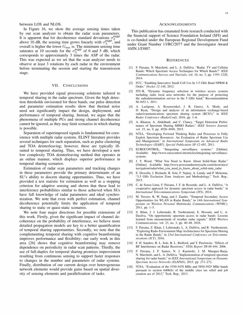
between LOS and NLOS.In Figure 16, we show the average sensing times taken
by our scan analyzer to obtain the radar scan parameters.It is apparent that for decoherence standard deviations σPARP
Λabove 10 dB, the sensing time grows linearly with σPARP
Λ , andoverall is higher the lower Gmax is. The minimum sensing timesaturates at 10 seconds for the σPARP
Λ of 0 and 5 dB, whichcorresponds to approximately 3 times the ASP of the radar.This was expected as we set that the scan analyzer needs toobserve at least 3 rotations by each radar in the environmentbefore terminating the session and starting the transmissionstage.
VII. CONCLUSIONS
We have provided signal processing solutions tailored totemporal sharing in the radar spectrum. Given the high detec-tion thresholds envisioned for these bands, our pulse detectionand parameter estimation results show that thermal noiseneed not significantly impact the design, deployment, andperformance of temporal sharing. Instead, we argue that thephenomena of multiple PUs and strong channel decoherencecannot be ignored, as they may limit scenarios in which sharingis possible.
Separation of superimposed signals is fundamental for coex-istence with multiple radar systems. ELINT literature providesseveral techniques for such separation, such as pulse clusteringand TOA deinterleaving; however, these are typically ill-suited to temporal sharing. Thus, we have developed a newlow complexity TOA deinterleaving method that operates inan online manner, which displays superior performance intemporal sharing scenarios.
Estimation of radar scan parameters and tracking changesin these parameters provide the primary determinants of anSU’s ability to discern sharing opportunities. Thus, we haveprovided a test statistic for estimation as well as a stoppingcriterion for adaptive sensing and shown that these lead tointerference probabilities similar to those achieved when SUshave full knowledge of radar parameters and ideal synchro-nization. We note that even with perfect estimation, channeldecoherence potentially limits the application of temporalsharing to static or quasi-static scenarios.
We note four major directions for possible extensions ofthis work. Firstly, given the significant impact of channel de-coherence on the probability of interference, we believe moredetailed propagation models are key to a better quantificationof temporal sharing opportunities. Secondly, we note that thecomplementing temporal sharing with cognitive beamformingimproves performance and flexibility; our early work in thisarea [26] shows that cognitive beamforming may removedependence on periodicity in radar scan patterns. Thirdly, theuse of full-duplex for temporal sharing promises improvementresulting from continuous sensing to support faster responsesto changes in the number and parameters of radar systems.Finally, distribution of our current design over heterogeneousnetwork elements would provide gains based on spatial diver-sity of sensing elements and parallelization of tasks.
ACKNOWLEDGMENTS
This publication has emanated from research conducted withthe financial support of Science Foundation Ireland (SFI) andis co-funded under the European Regional Development Fundunder Grant Number 13/RC/2077 and the Investigator Award10/IN.1/I3007.
REFERENCES
[1] F. Paisana, N. Marchetti, and L. A. DaSilva, “Radar, TV and CellularBands: Which Spectrum Access Techniques for Which Bands?” IEEECommunications Surveys and Tutorials, vol. 16, no. 3, pp. 1193–1220,2014.
[2] FCC, “Enabling Innovative Small Cell Use In 3.5 GHz Band NPRM &Order,” Docket 12-148, 2012.
[3] ITU-R, “Dynamic frequency selection in wireless access systemsincluding radio local area networks for the purpose of protectingthe radiodetermination service in the 5 GHz band,” RecommendationM.1652-1, 2011.
[4] A. Lackpour, A. Rosenwinkel, J. R. Guerci, A. Mody, andD. Ryan, “Design and analysis of an information exchange-basedradar/communications spectrum sharing system (RCS3),” in IEEERadar Conference (RadarConf), 2016, pp. 1–6.
[5] A. Khawar, A. Abdelhadi, and C. Clancy, “Target Detection Perfor-mance of Spectrum Sharing MIMO Radars,” IEEE Sensors Journal,vol. 15, no. 9, pp. 4928–4940, 2015.
[6] NTIA, “Developing Forward Thinking Rules and Processes to FullyExploit Spectrum Resources: An Evaluation of Radar Spectrum Useand Management,” in International Symposium on Advanced RadioTechnologies (ISART), Special Publication SP-12-485, 2011.
[7] EUROCONTROL, “Integrating surveillance systems.” [Online].Available: http://www.eurocontrol.int/articles/integrating-surveillance-systems
[8] J. Y. Wood, “What You Need to Know About Solid-State Radar.”[Online]. Available: http://www.powerandmotoryacht.com/electronics/navigation/radar/what you need to know about solid-state radar
[9] E. Drocella, J. Richards, R. Sole, F. Najmy, A. Lundy, and P. Mckenna,“3.5 GHz Exclusion Zone Analyses and Methodology,” Tech. Rep.,2015.
[10] C. de Souza Lima, F. Paisana, J. F. de Rezende, and L. A. DaSilva, “Acooperative approach for dynamic spectrum access in radar bands,” inInternational Telecommunications Symposium (ITS), 2014.
[11] M. Tercero, K. W. Sung, and J. Zander, “Temporal Secondary AccessOpportunities for WLAN in Radar Bands,” in 14th International Sym-posium on Wireless Personal Multimedia Communications (WPMC),2011, pp. 1–5.
[12] Z. Khan, J. J. Lehtomaki, R. Vuohtoniemi, E. Hossain, and L. A.Dasilva, “On opportunistic spectrum access in radar bands: Lessonslearned from measurement of weather radar signals,” IEEE WirelessCommunications, vol. 23, no. 3, pp. 40–48, 2016.
[13] F. Paisana, Z. Khan, J. Lehtomaki, L. A. DaSilva, and R. Vuohtoniemi,“Exploring Radio Environment Map Architectures for Spectrum Sharingin the Radar Bands,” in 23rd International Conference on Telecommu-nications (ICT), 2016.
[14] F. H. Sanders, R. L. Sole, B. L. Bedford, and T. Pawlowitz, “Effects ofRF Interference on Radar Receivers,” NTIA Report TR-06-444, 2006.
[15] F. Paisana, J. F. Santos, N. J. Kaminski, J. M. Marquez-Barja,N. Marchetti, and L. A. DaSilva, “Implementation of temporal spectrumsharing for radar bands,” in IEEE International Symposium on DynamicSpectrum Access Networks (DySPAN), 2015, pp. 271–272.
[16] NTIA, “Evaluation of the 5350-5470 MHz and 5850-5925 MHz bandspursuant to section 6406(b) of the middle class tax relief and jobcreation act of 2012,” Tech. Rep., 2013.

15
(a) antenna maximum gain Gmax of 35 dBi. (b) σPARPΛ = 15 dB.
Fig. 15: ROC curves of the scan analyzer over different channel decoherence and radar antenna gain levels. In red, we represent the obtainedperformance if the estimation of the scan parameters and the synchronization was perfect.
Fig. 16: Sensing time for different radar antenna gain levels Gmax anddecoherence standard deviations σPARP
Λ .
[17] A. Lackpour, M. Luddy, and J. Winters, “Overview of interferencemitigation techniques between WiMAX networks and ground basedradar,” in 20th Annual Wireless and Optical Communications Confer-ence (WOCC), 2011.
[18] V. Ramaswamy and J. T. Correia, “Understanding the impact ofRADAR interference on IEEE 802.11 MAC in spectrum sharing envi-ronments,” in IEEE Military Communications Conference (MILCOM),2015, pp. 73–78.
[19] M. Tercero, K. W. Sung, and J. Zander, “Impact of aggregate interfer-ence on meteorological radar from secondary users,” in IEEE WirelessCommunications and Networking Conference (WCNC), 2011.
[20] DARPA, “Shared Spectrum Access for Radar and Communications(SSPARC),” Tech. Report, 2013.
[21] G. M. Jacyna, B. Fell, and D. McLemore, “A high-level overview offundamental limits studies for the DARPA SSPARC program,” IEEERadar Conference (RadarConf), 2016.
[22] H. Deng and B. Himed, “Interference mitigation processing forspectrum-sharing between radar and wireless communications systems,”IEEE Transactions on Aerospace and Electronic Systems, vol. 49, no. 3,pp. 1911–1919, 2013.
[23] A. Babaei, W. H. Tranter, and T. Bose, “A practical precoding approachfor radar/communications spectrum sharing,” in 8th International Con-ference on Cognitive Radio Oriented Wireless Networks (CROWN-COM), 2013, pp. 13–18.
[24] A. Khawar, A. Abdelhadi, and T. C. Clancy, “On The Impact of Time-Varying Interference-Channel on the Spatial Approach of SpectrumSharing between S-band Radar and Communication System,” 2014IEEE Military Communications Conference, 2014.
[25] F. Paisana, J. P. Miranda, N. Marchetti, and L. A. DaSilva, “Database-aided sensing for radar bands,” in IEEE International Symposium onDynamic Spectrum Access Networks (DYSPAN), 2014, pp. 1–6.
[26] F. Paisana, D. Finn, N. Marchetti, and L. DaSilva, “Reduction ofradar band exclusion zones through database-aided beamforming,” in
IEEE International Symposium on Dynamic Spectrum Access Networks(DySPAN), 2015.
[27] J. F. Santos, F. Paisana, N. J. Kaminski, J. M. Marquez-Barja, and L. A.DaSilva, “Context-aware radar modeling framework,” in IEEE Interna-tional Symposium on Dynamic Spectrum Access Networks (DySPAN),2015.
[28] F. Paisana, L. A. Dasilva, and N. Marchetti, “Spectrum Sharing Tech-niques for Radar Bands,” PhD Thesis, Trinity College, Dublin, 2017.
[29] A. Ansari, D. Zhang, and S. Mahlke, “Parade: A versatile parallel archi-tecture for accelerating pulse train clustering,” in IEEE 7th Symposiumon Application Specific Processors (SASP), 2009, pp. 88–93.
[30] A. W. Ata’a and S. N. Abdullah, “Deinterleaving of radar signals andPRF identification algorithms,” IET Radar Sonar Navigation, vol. 1,no. 5, pp. 341–347, 2007.
[31] Y. Kuang, Q. Shi, Q. Chen, L. Yun, and K. Long, “A Simple Way toDeinterleave Repetitive Pulse Sequences,” in 7th WSEAS Conferenceon mathematical methods and computational techniques in ElectricalEngineering, 2005, pp. 218–222.
[32] K. Mahmoud, P. A. Mansour, and F. Forouhar, “A New Methodfor Detection of Complex Pulse Repetition Interval Modulations,” inInternational Conference on Signal Processing Proceedings (ICSP),vol. 3, 2012, pp. 1705–1709.
[33] M. Ahmadi and K. Mohamedpour, “A New Method for RecognizingPulse Repetition Interval Modulation,” in 2009 International Conferenceon Signal Processing Systems, 2009, pp. 146–151.
Francisco Paisana received his Master’s Degree inelectrical engineering and computers from InstitutoSuperior Tecnico, Portugal in 2012. He subsequentlycompleted his PhD in wireless communications atTrinity College Dublin in 2016. He is currently aPostDoc at CONNECT Research Centre, Trinity Col-lege Dublin. His research interests include software-defined radio, spectrum sharing, machine learning,signal processing and cognitive radio.

16
Nicholas J. Kaminski conducts research focusedon extending the bounds of wireless technology bydeploying targeted intelligence to act in harmonywith flexible radio systems. He advances distributedradio intelligence through experimentation-based re-search and furthers wireless communications by in-corporating techniques for understanding communi-cations from complex systems science. Dr. Kaminskireceived his masters degree in Electrical Engineeringin 2012 and his Ph.D. in 2014 from Virginia Tech,USA. During this time he was funded as a Bradley
Fellow at the Bradley Department of Electrical and Computer Engineering atVirginia Tech, USA.
Nicola Marchetti received the Ph.D. degree inwireless communications and the two M.Sc. de-grees in electronic engineering and in mathematics.He is an Assistant Professor with Trinity CollegeDublin, Ireland and performs his research underthe Irish Research Centre for Future Networks andCommunications (CONNECT). His collaborations todate include Samsung, Nokia, Huawei, Intel amongothers. He has authored 110 publications and holds2 patents. His research interests include PHY andRRM for 5G, cognitive radio and dynamic spectrum
access, complex systems science, and integrated optical wireless networks.
Luiz A. DaSilva holds the chair of Telecommunica-tions at Trinity College, where he is a co-principalinvestigator of CONNECT, a telecommunicationscentre funded by the Science Foundation Ireland.Prior to joining TCD, Prof DaSilva was a tenuredprofessor in the Bradley Department of Electrical andComputer Engineering at Virginia Tech. His researchfocuses on distributed and adaptive resource manage-ment in wireless networks, and in particular radioresource sharing and the application of game theoryto wireless networks. Prof DaSilva is a principal
investigator on research projects funded by the National Science Foundation,the Science Foundation Ireland, and the European Commission. Prof DaSilvaisan IEEE Communications Society Distinguished Lecturer and a Fellow ofTrinity College Dublin. He is also a Fellow of the IEEE, for contributions tocognitive networks and to resource management in wireless networks.