1 summary and featuressummary and features
TRANSCRIPT
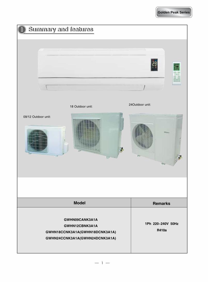
Model Remarks
GWHN09CANK3A1A
GWHN12CBNK3A1A
GWHN18CCNK3A1A(GWHN18DCNK3A1A)
GWHN24CCNK3A1A(GWHN24DCNK3A1A)
1 Summary and featuresSummary and features
09/12 Outdoor unit:
18 Outdoor unit:24Outdoor unit:
1Ph 220~240V 50Hz
R410a
Golden Peak Series
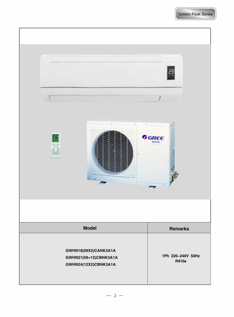
Model Remarks
GWHN18(09X2)CANK3A1A
GWHN21(09+12)CBNK3A1A
GWHN24(12X2)CBNK3A1A
1Ph 220~240V 50HzR410a
Golden Peak Series
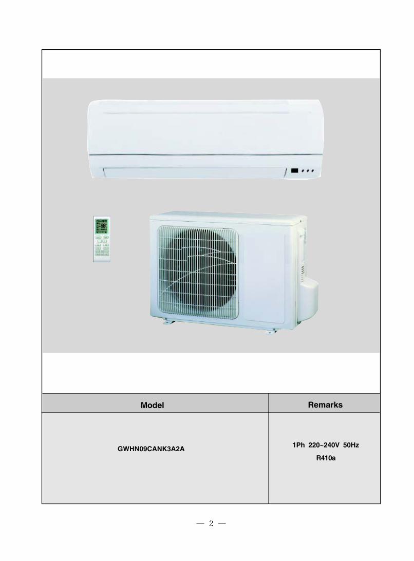
Model Remarks
GWHN09CANK3A2A 1Ph 220~240V 50Hz
R410a

Model Remarks
GWHN18(09X2)CANK3A2A
GWHN21(09+12)CBNK3A2A1Ph 220~240V 50Hz
R410a

COOLING HEATING COOLING HEATING
2650 /9050 2850/ 9730 3516/12000 4015/13700
820 785 1080 1104
1110 1150 1500 1500
5.69 5.9 7.6 7.6
Model of Indoor Unit
Fan Motor Speed (r/min) (H/M/L)
Output of Fan Motor (w)Input of Heater (w)Fan Motor Capacitor (uF)Fan Motor RLA(A)Fan Type-PieceDiameter-Length (mm)
Evaporator
Pipe Diameter (mm)Row-Fin Gap(mm)Coil length (l) x height (H) x coilwidth (L)Swing Motor ModelOutput of Swing Motor (W)Fuse (A)Sound Pressure Level dB (A)(H/M/L)Sound Power Level dB (A)(H/M/L)***Dimension (W/H/D) ( mm)
Dimension of Package(W/H/D)(mm)
Net Weight /Gross Weight (kg) 9/12
51/49/46/42
805 x 280 x 215
860 x 355 x 280
MP24AA1.5
PCB 3.15A
41/39/36/32
Aluminum fin-copper tube
72-1.5
656 x 25.4 x 304.8
10.254
Cross flow fan – 1φ99*644
GWHN12CBNK3A1A/I
Cool:ing 1120/1010/890/760Heating: 1120/1010/900/780
9/
A
GWHN12CBNK3A1A
220-240V
50Hz
580
1
3.26/3.64
A
500
1
8/10
3.21/3.61
Indoorunit
50/48/46/44
740 x 250 x 180
790 x 320 x 264
MP28EC2
3.15
40/38/36/34
Aluminum fin-copper tube
72-1.6
576X142X145
10.263
Cross flow fan – 197
GWHN09CANK3A1A/I
Cool:ing 1160/1065/959/861Heating: 1160/1067/960/860
/
GWHN09CANK3A1A
220-240V
50Hz
Energy Class
Total Capacity (W/Btu/h)
Power Input (W)
Rated Input (W)
Rated Current (A)
Air Flow Volume (m3/h) (H/M/L)**
Dehumidifying Volume (l/h)
EER / C.O.P (W/W)
Model
Function
Rated Voltage
Rated Frequency
Technical specificationsTechnical specifications2
Golden Peak Series

GWHN09DANK3A1A/O GWHN12DBNK3A1A/OHIGHLY Gree
ASG102CV-B7AT QXA-133uB030Rotary Rotory
18A 324.05 5.1875 1160
KA-172-LYGN914 B250-150-141E
-5~43 -15~46
7 71-1.6 2-1.4
608X495X205 731X495X25.4830 85030W 300.345 0.35
2 21400 1700
Axial fan -1 Axial fan –1400 400
Auto defrost Auto defrostT1 T1I I
IP24 IP24
3 3.8
1 1.2
52 5262 62
848X540X320 848X540X320878X590X360 878X590X360
35/40 40/44R410A/0.75 R410A/1.10
5 525 25
Liquid Pipe (mm) Φ6(1/4") Φ6(1/4")Gas Pipe (mm) Φ9.52(3/8") Φ12(1/2")Height (m) 5 5Length (m) 10 10
Aluminum fin-copper tube
CapillaryCapacitor
Dimension of Package (L/W/H)(mm)
CondenserPipe Diameter (mm)Rows-Fin Gap(mm)Coil length(l) x height(H) x coil width(L)Fan Motor Speed (rpm) (H/M/L)Output of Fan Motor (W)
Net Weight /Gross Weight (kg)
Permissible Excessive OperatingPressure for the Suction Side(MPa)
Sound Pressure Level dB (A) (H/M/L)Sound Power Level dB (A) (H/M/L)Dimension (W/H/D) (mm)
OuterDiameter
Refrigerant Charge (kg)
Outdoorunit
Connection Pipe
Gas additional charge(g/m)Length (m)
MaxDistance
Model of Outdoor UnitCompressor Manufacturer/trademarkCompressor ModelCompressor TypeL.R.A. (A)Compressor RLA(A)Compressor Power Input(W)Overload ProtectorThrottling MethodStarting MethodWorking Temp Range (℃)
Fan Motor RLA(A)Fan Motor Capacitor (uF)Air Flow Volume of Outdoor UnitFan Type-Piece
Moisture ProtectionPermissible Excessive OperatingPressure for the Discharge Side(MPa)
Fan Diameter (mm)Defrosting MethodClimate TypeIsolation
The above data is subject to change without notice. Please refer to the nameplate of the unit.

COOLING HEATING COOLING HEATING
18000 19500 22000 23200
1640 1670 2120 2120
2500 2550 3000 3000
10.9 11.1 13 13
Model of Indoor Unit
Fan Motor Speed (r/min) (H/M/L)
Output of Fan Motor (w)Input of Heater (w)Fan Motor Capacitor (uF)Fan Motor RLA(A)Fan Type-PieceDiameter-Length (mm)
Evaporator
Pipe Diameter (mm)Row-Fin Gap(mm)Coil length (l) x height (H) x coilwidth (L)Swing Motor ModelOutput of Swing Motor (W)Fuse (A)Sound Pressure Level dB (A)(H/M/L)Sound Power Level dB (A)(H/M/L)***Dimension (W/H/D) ( mm)
Dimension of Package(W/H/D)(mm)
Net Weight /Gross Weight (kg)
EER / C.O.P (W/W)
Model
Function
Rated Voltage
Rated Frequency
GWHN18CCNK3A1A(GWHN18DCNK3A1A)
220-240V~
50Hz
Energy Class
Total Capacity (Btu/h)
Power Input (W)
Rated Input (W)
Rated Current (A)
Air Flow Volume (m3/h) (H/M/L)**
Dehumidifying Volume (l/h)
GWHN18CCNK3A1A/I(GWHN18DCNK3A1A/I)
1200/1050/900
20/1
0.4Cross flow fan – 1
φ96 X 797
Aluminum fin-copper tube
Φ72-1.6
785X340.51X25.4
14/19
3.21
Indoorunit
58/55/52/48
1020X228X310
1078X390X325
MP35XX2.5
PCB 3.15A Transformer 0.2A
48/45/42/38
A
GWHN24CCNK3A1A(GWHN24DCNK3A1A)
220-240V~
50Hz
830/670/620
4
3.01
B
830/670/600
3
GWHN24CCNK3A1A/I(GWHN24DCNK3A1A/I)
1200/1050/950
20/1
0.4Cross flow fan – 1
φ96 X 797
Aluminum fin-copper tube
Φ72.5-1.6
785X340.51X25.4
MP35XX2.5
PCB 3.15A Transformer 0.2A
48/45/42/39
15/20
58/55/52/49
1020X228X310
1078X390X325
Golden Peak Series

GWHN18CCNK3A1A/O(GWHN18DCNK3A1A/O)
GWHN24CCNK3A1A/O(GWHN24DCNK3A1A/O)
Shanghai Hitachi ElectricalAppliances Co,Ltd./Highly
Shanghai Hitachi ElectricalAppliances Co,Ltd./Highly
ASH210SV-C8LU ASH264SV-C8LUrotary compressor rotary compressor
40 607.5 10.3
1725 2215
内置 内置
Capillary CapillaryCapacitor Capacitor
-7℃≤T≤43℃ -7℃≤T≤43℃Aluminum fin-copper tube Aluminum fin-copper tube
7 Φ9.522-1.4 2-1.4
806×660×25.4 804X660X44860 78048 68
0.62 1.23.5 2.5
2790m3/h 3400m3/hAxial fan –1 Axial fan –1
Φ473 Φ472Auto defrost Auto defrost
T1 T1I I
IP24 IP24
3.8 3.8
1.2 1.2
56/54/52 56/54/52 66/64/62 66/64/62
913X680X378 950X700X412994X720X428 1100X755X450
46/50 59/64R410/1.6 R410/1.85
4 450 50
Liquid Pipe (mm) Φ6 Φ9.52Gas Pipe (mm) Φ12 Φ16Height (m) 5 5Length (m) 10 10
Fan Motor Speed (rpm) (H/M/L)Output of Fan Motor (W)
CondenserPipe Diameter (mm)Rows-Fin Gap(mm)Coil length(l) x height(H) x coil width(L)
Net Weight /Gross Weight (kg)
Permissible Excessive OperatingPressure for the Suction Side(MPa)
Sound Pressure Level dB (A) (H/M/L)Sound Power Level dB (A) (H/M/L)Dimension (W/H/D) (mm)Dimension of Package (L/W/H)(mm)
OuterDiameter
Refrigerant Charge (kg)
Outdoorunit
Connection Pipe
Gas additional charge(g/m)Length (m)
MaxDistance
Model of Outdoor Unit
Compressor Manufacturer/trademark
Compressor ModelCompressor TypeL.R.A. (A)Compressor RLA(A)Compressor Power Input(W)Overload ProtectorThrottling MethodStarting MethodWorking Temp Range (℃)
Fan Motor RLA(A)Fan Motor Capacitor (uF)Air Flow Volume of Outdoor UnitFan Type-Piece
Moisture ProtectionPermissible Excessive OperatingPressure for the Discharge Side(MPa)
Fan Diameter (mm)Defrosting MethodClimate TypeIsolation
The above data is subject to change without notice. Please refer to the nameplate of the unit.

COOLING HEATING COOLING HEATING
2650 2850 2650/3500 2800/3800
1750 1860 2040 2020
2460 2460 3120 3120
7.95 8.1 8.87 8.78
550/500/450/400
600/550/500/450
3.02 3.27
B C
Model of Indoor UnitGWHN21(09)CANK3A1A/I
GWHN21(12)CBNK3A1A/I
Fan Motor Speed (r/m in)(H/M/L)
1160/1060/960/860
1250/1100/1000/900
Output of Fan Motor (w) 20 9Input of Heater (w)Fan Motor Capacitor (uF)Fan Motor RLA(A) 0.263 0.254Fan Type-PieceDiam eter-Length (m m) φ97 X 583 φ99 X 644
Evaporator
Pipe Diameter (m m)Row-Fin Gap(mm )Coil length (l) x height (H) xcoil width (L)Swing Motor Model MP28EC MP24AAOutput of Swing Motor (W) 2.0 1.5Fuse (A)Sound Pressure Level dB(A) (H/M/L)Sound Power Level dB (A)(H/M/L)***Dimension (W/H/D) ( m m) 746/315/260 805/280/180
Dimension of Package(W/H/D)(mm) 790/325/275 860/355/280
Net Weight/Gross Weight(kg) 8/10 9/12
2-1.5
656X25.4X304.8
Aluminum fin-copper tube
φ7
860/355/280
9/12
MP24AA1.5
PCB 3.15A
41/39/36/32
51/49/46/42
805/280/215
Cross flow fan – 1φ99X644
GWHN24(12)CBNK3A1A/I
Cool:ing1120/1010/890/760;
Heating:1120/1010/900/780
9/1
0.254
600X2
2
GWHN24(12X2)CBNK3A1A
220-240V~
50HZ
COOLING
3500X2
2320
3100
15.6
EER / C.O.P (W/W)
Model
Function
Rated Voltage
Rated Frequency
GWHN18(09X2)CANK3A1A
220-240
50
Energy Class
Total Capacity (W/Btu/h)
Power Input (W)
Rated Input (W)
Rated Current (A)
Air Flow Volum e (m3/h) (H/M/L)**
Dehumidifying Volum e (l/h)
8/10
3.01/3.06
φ97X583
GWHN18(09)CANK3A1A/I
1160/1060/960/860
20/
Indoorunit
50/48/46/44
746/315/260
790/325/275
MP28EC2
PCB 3.15A
40/38/36/34
2-1.6
576X283X279
3.01/3.21
B/C
550/500/450/400
1
GWHN21(09+12)CBNK3A1A
220-240
50
1.0/1.2
1
Cross flow fan – 1
/
B/D
10.263
Cross flow fan -1
50/48/46/44
PCB 3.15A
40/38/36/34
2 - 1.6
576X283X279
Golden Peak Series

GWHN18(09X2)DANK3A1A/O
GWHN21(09+12)DBNK3A1A/O
GWHN24(12X2)DBNK3A1A/O
LANDA MITSUBISHI MITSUBISHIQXA-B109uB030 KN104VGMMC RN135VHEMC
rotory rotory ROTARY20 19/27 274 4.08/5.6 5
925 900/1230 1130B165-150-241H / -
Capillary Capillary CapillaryCapacitor Capacitor Capacitor
-5℃ - 43℃ -5℃ - 43℃ -15℃ - 43℃
φ7 φ8 ¢82-1.4 2- 1.4 2-1.4
664X178X705 660X216X660 660x216x38.1840 840 84068 68 680.3 0.3 0.653.5 3.5 3.5
/ / 5000Axial fan –1 Axial fan –1 Axial fan -1
472 472 472Auto defrost Auto defrost Auto defrost
T1 T1 T1I I I
IP24 IP24 IP24
3 3 3.8
1 1 1.2
59 59 6069 69 70
1018/700/412 1018/700/412 1018/700/4121100/755/450 1100/755/450 1100/755/450
65/70 65/70 65/70 R410A 0.9/0.9 R410A 0.9/1.15 R410A 1.0/1.0
5 5 530 30 30
Liquid Pipe (mm) φ6 φ6/φ6 ¢6Gas Pipe (mm) φ9.52 φ9.52/φ12 ¢12Height (m) 5 5 5Length (m) 10 10 10
Coil length(l) x height(H) x coil w idth(L)
Net Weight /Gross Weight (kg)
Permissible Excessive OperatingPressure for the Suction Side(MPa)
Sound Pressure Level dB (A)Sound Power Level dB (A)Dimension (W/H/D) (mm)Dimension of Package (L/W/H)(mm)
Fan Type-Piece
Fan Motor Speed (rpm) (H/M/L)Output of Fan Motor (W)
OuterDiameter
Refrigerant Charge (kg)
Outdoorunit
ConnectionPipe
Gas additional charge(g/m)Length (m)
MaxDistance
Model of Outdoor Unit
Compressor Manufacturer/trademarkCompressor ModelCompressor TypeL.R.A. (A)Compressor RLA(A)Compressor Power Input(W)Overload ProtectorThrottling MethodStarting MethodWorking Temp Range (℃)CondenserPipe Diameter (mm)Rows-Fin Gap(mm)
Aluminum fin-copper tube
Permissible Excessive OperatingPressure for the DischargeSide(MPa)
Fan Diameter (mm)Defrosting MethodClimate TypeIsolation
Fan Motor RLA(A)Fan Motor Capacitor (uF)Air Flow Volume of Outdoor Unit
Moisture Protection
The above data is subject to change without notice. Please refer to the nameplate of the unit.

COOLING HEATING COOLING HEATING COOLING HEATING
2650 /9050 2850/ 9730 2650 2850 2650/3500 2800/3800
820 785 1750 1860 2040 2020
1110 1150 2460 2460 3120 3120
5.69 5.9 7.95 8.1 8.87 8.78
550/500/450/400 600/550/500/450
Model of Indoor UnitGWHN21(09)C
ANK3A2A/IGWHN21(12)C
BNK3A2A/I
Fan Motor Speed (r/min)(H/M/L)
1160/1060/960/860
1250/1100/1000/900
Output of Fan Motor (w) 20 9Input of Heater (w)Fan Motor Capacitor (uF)Fan Motor RLA(A) 0.263 0.254Fan Type-PieceDiameter-Length (mm) φ97 X 583 φ99 X 644Evaporator
Pipe Diameter (mm)Row-Fin Gap(mm)Coil length (l) x height (H) xcoil width (L)Swing Motor Model MP28EC MP24AAOutput of Swing Motor (W) 2.0 1.5Fuse (A)Sound Pressure Level dB (A)(H/M/L)Sound Power Level dB (A)(H/M/L)***Dimension (W/H/D) ( mm) 746/315/260 805/280/180
Dimension of Package (L/W/H) ( mm) 790/325/275 860/355/280
Net Weight /Gross Weight (kg) 8/10 9/12
GWHN18(09X2)CANK3A2A
GWHN21(09+12)CBNK3A2A
220-240 220-240
40/38/36/34
500
1
A
10.263
Cross flow fan – 1
576X142X145
GWHN09CANK3A2A/I
Cooling1160/1065/959/861
Heating:1160/1067/960/860
8/10
3.21/3.61
Indoorunit
50/48/46/44
740 x 250 x 180
790 x 320 x 264
MP28EC2
3.15
φ97X583
20/
GWHN09CANK3A2A
220-240V
50Hz
Energy Class
Total Capacity (Btu/h)
Power Input (W)
Rated Input (W)
Rated Current (A)
Air Flow Volume (m3/h) (H/M/L)**
Dehumidifying Volume (l/h)
EER / C.O.P (W/W)
Model
Function
Rated Voltage
Rated Frequency 50 50
550/500/450/400
1 1.0/1.2
3.01/3.06 3.01/3.21
B/D B/C
GWHN18(09)CANK3A2A/I
1160/1060/960/860
20/
Cross flow fan -1 Cross flow fan – 1φ97X583
/1 1
0.263
40/38/36/34 40/38/36/34
576X283X279 576X283X279
MP28EC2
8/10
Aluminum fin-copper tube
φ72-1.6
50/48/46/44 50/48/46/44
746/315/260
790/325/275
PCB 3.15A PCB 3.15A
Golden Peak Series

GWHN09DANK3A1A/OGWHN18(09X2)DANK
3A1A/OGWHN21(09+12)DBN
K3A1A/OHIGHLY LANDA MITSUBISHI
ASG102CV-B7AT QXA-B109uB030KN104VGMMCRN145VHEMC
Rotary rotory rotory18A 20 19/274.05 4 4.08/5.6875 925 900/1230
KA-172-LYGN914 B165-150-241H /
φ7 φ7 φ81-1.6 2-1.4 2- 1.4
608X495X205 664X178X705 660X216X660830 840 84030 68 68
0.345 0.3 0.32 3.5 3.5
1400 / /Axial fan -1 Axial fan –1 Axial fan –1
400 472 472Auto defrost Auto defrost Auto defrost
T1 T1 T1I I I
IP24 IP24 IP24
3 3 3
1 1 1
52 59 5962 69 69
848X540X320 1018/700/412 1018/700/412878X590X360 1100/755/450 1100/755/450
35/40 65/70 65/70R410A/0.75 R410A 0.9/0.9 R410A 0.9/1.15
5 5 525 30 30
Liquid Pipe (mm) Φ6(1/4") φ6 φ6/φ6Gas Pipe (mm) Φ9.52(3/8") φ9.52 φ9.52/φ12Height (m) 5 5 5Length (m) 10 10 10
Fan Motor Speed (rpm) (H/M/L)Output of Fan Motor (W)
Condenser
Pipe Diameter (mm)Rows-Fin Gap(mm)Coil length(l) x height(H) x coil width(L)
Net Weight /Gross Weight (kg)
Permissible Excessive OperatingPressure for the Suction Side(MPa)
Sound Pressure Level dB (A)Sound Power Level dB (A)Dimension (W/H/D) (mm)Dimension of Package (L/W/H)(mm)
OuterDiameter
Refrigerant Charge (kg)
Outdoorunit
Connec-tionPipe
Gas additional charge(g/m)Length (m)
MaxDistance
Model of Outdoor Unit
Compressor Manufacturer/trademark
Compressor Model
Compressor TypeL.R.A. (A)Compressor RLA(A)Compressor Power Input(W)Overload ProtectorThrottling Method
Starting Method
Working Temp Range (℃)
Fan Motor RLA(A)Fan Motor Capacitor (uF)Air Flow Volume of Outdoor UnitFan Type-Piece
Moisture ProtectionPermissible Excessive OperatingPressure for the Discharge Side(MPa)
Fan Diameter (mm)Defrosting MethodClimate TypeIsolation
Aluminum fin-copper tube
Capillary
Capacitor
-5~43

Part namePart name
Wall PipeLED displayer
Remote control window
Guide louver
Indoor unit
Outdoor unit
Front Panel
Filter
Air in
Air out
Drainage hose
Air in
Air out
Manual switch
Wireless remote control
Wrapping Tape
Set Temp
Heat Cooling
Co
nn
ect
ion
pip
e
3
LED displayer
DRY Run
Golden Peak Series
Note: the outdoor unit of one and one plese refer to the outdoor unit of 09/12 outdoor unit.

Wall Pipe
Guide louver
Indoor unit
Outdoor unit
Front Panel
Filter
Air in
Air out
Drainage hose
Air in
Air out
Manual switch
Wireless remote control
Wrapping Tape
Indicator light
Heat
Cooling
Co
nn
ect
ion
pip
e
Run
Remote control window

Wall Pipe
LED displayer
Remote control window
Guide louver
Indoor unit
Outdoor unit
Front Panel
Filter
Air in
Air out
Drainage hose
Air in
Air out
Manual switch
Wireless remote control
Wrapping Tape
Set Temp
Heat Cooling
Connection pipe
LED displayer
DRY Run

Wall Pipe
Remote control window
Guide louver
Indoor unit
Outdoor unit
Front Panel
Filter
Air in
Air out
Drainage hose
Air in
Air out
Manual switch
Wireless remote control
Wrapping Tape
Heat
Cooling
Connection pipe
Run
Indicator light
(09) Indoor unit
(12) Indoor unit

Tube exit
Air inlet
Rear View
RightLeft
Ceiling
Wall-Mounting Plate
W D
HOutline and installation dimensions of indoor unit
4 Outline and installation dimensionOutline and installation dimension
Wall-Mounting Plate:
09
12
18/24
Model W(㎜) H(㎜) D(㎜)GWHN09CANK3A1A/I 740 250 180
GWHN18(09)CANK3A1A/I GWHN21(09)CANK3A1A/I 746 315 260GWHN12CBNK3A1A/I 805 280 215
GWHN21(12)CBNK3A1A/I 805 280 180GWHN18CCNK3A1A/I(GWHN18DCNK3A1A/I)GWHN24CCNK3A1A/I(GWHN24DCNK3A1A/I)
1020 228 310
Golden Peak Series

Tube exit
Air inlet
Rear View
RightLeft
Ceiling
Wall-Mounting Plate
W D
H
Wall-Mounting Plate:
09
12
Model W(㎜) H(㎜) D(㎜)GWHN09CANK3A2A/I 740 250 180
GWHN18(09)CANK3A2A/I GWHN21(09)CANK3A2A/I 746 315 260GWHN21(12)CBNK3A2A/I 805 280 180

Outline and installation dimensions of outdoor unit
Unit:mm
GWHN09CANK3A1A/O, GWHN12CBNK3A1A/O
Bolt
Nut
Wrench
overover
over
over

913 378
68
0
550
34
2
GWHN18CCNK3A1A/O(GWHN18DCNK3A1A/O)
Bolt
Nut
Wrench
Unit:mm
Golden Peak Series

Unit:mm
950
70
0
572
37
8
GWHN24CCNK3A1A/O(GWHN24DCNK3A1A/O)
BoltNut
Wrench
over
overover
over

Bolt
Nut
Wrench
1018 412
70
0
572
37
8
GWHN18(09X2)DANK3A1A/O, GWHN21(09+12)DBNK3A1A/O,GWHN24(12X2)DBNK3A1A/O
Unit:mm
Golden Peak Series

Electrical circuit diagramElectrical circuit diagram55555
Golden Peak Series


Golden Peak Series


These circuit diagrams are subject to change without notice, please refer to the one supplied with the unit.
Golden Peak Series

66666
�
�
Manual of functions of remote controller and operation method
Manual 1 of functions of remote controller
6.1.1 Temperature parameterThe room setting temperature(Tpreset)The room ambient temperature (Tamb)
6.1.2Basic Functions Once energized, the compressor should in no way be restarted unless after 3-minute time interval at least. For the first energization, the compressor will be started without 3-minute lag. The compressor, once started,will not be stopped within 6 minutes with the change of room temperature.
Cooling Mode Cooling Conditions and Process
When T amb.≥Tpreset +1℃, the unit will run under cooling mode, in which case the compressor and outdoor fan will start and the indoor fan will run at setting speed. When T amb.≤Tpreset -1℃, the compressor and the outdoor fan will stop, the indoor fan will run at setting speed. When Tpreset -1 <T℃ amb.< Tpreset +1 , the unit will maintain its original operating status.℃ Under this mode, the switchover valve will not be powered on, and the setting temperature range is16 ~30 .
Tpreset +1℃
Tpreset -1℃
Compressor
Outdoor fan Indoor fan Preset speed
Run
Tamb
Stop
Stop cooling
Start cooling
Original operating status
≥6 min. ≥3 min. ≥6 min.
6.1.2.1.3 Protection Antifreeze Protection
If it is detected that the system is under antifreeze protection, the compressor and outdoor fan will be stopped, and the indoor fan will run at setting speed. When antifreeze protection is released and the compressor has stopped for 3 minutes, the unit will resume its original operating status.
During antifreeze protection
3 min.
StopRun
Preset speed
Compressor
Outdoor fan Indoor fan
6.1.2.2 DRY Modes
6.1.2.2 .1 The conditions and process of DRY +2 , the unit will run under DRY cooling mode, in which case the compressor and outdoor fan ℃
will be started and the indoor fan will run at low speed. When T amb. > Tpreset
When Tpreset -2℃≤T amb.≤Tpreset +2℃, the unit will run under DRY mode, in which case the indoor fan will keep run at low speed, the compressor and the outdoor fan will be stopped after 6 minutes . After 4 minutes,the compressor and the outdoor fan will be restarted. The dehumidifying process is so repeated in cycle. . When Tamb.< Tpreset-2℃, the compressor and outdoor fan will be stopped, the indoor fan will run at low speed. Under this mode, the switchover valve will not be powered on, and the setting temperature range is16 ~30 .
Golden Peak Series
Tpreset +2℃
Tpreset -2℃
Tamb
Compressor Outdoor fan
Indoor fan
Cooling
Dry
Stop 6 min. 6 min. 4 min. 4 min.
low speed
Run Stop
6.1.2.2.3 Protection Antifreeze Protection
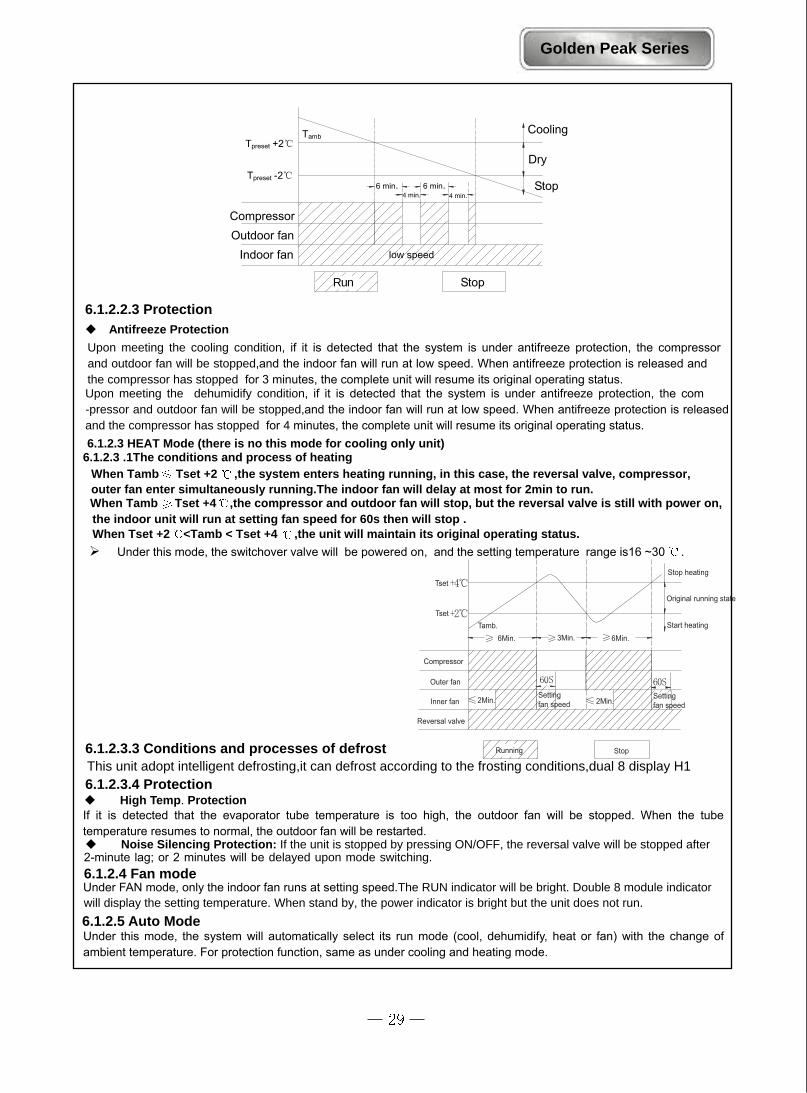
Upon meeting the cooling condition, if it is detected that the system is under antifreeze protection, the compressor and outdoor fan will be stopped,and the indoor fan will run at low speed. When antifreeze protection is released and the compressor has stopped for 3 minutes, the complete unit will resume its original operating status. Upon meeting the dehumidify condition, if it is detected that the system is under antifreeze protection, the com -pressor and outdoor fan will be stopped,and the indoor fan will run at low speed. When antifreeze protection is released and the compressor has stopped for 4 minutes, the complete unit will resume its original operating status. 6.1.2.3 HEAT Mode (there is no this mode for cooling only unit)
6.1.2.3 .1The conditions and process of heating
Tset
Tset
Compressor
Outer fan
Inner fan
Reversal valve
Running Stop
Stop heating
Original running state
Start heatingTamb.6Min. 3Min. 6Min.
2Min.Settingfan speed 2Min.
Settingfan speed
When Tamb Tset +2 ,the system enters heating running, in this case, the reversal valve, compressor, outer fan enter simultaneously running.The indoor fan will delay at most for 2min to run.When Tamb Tset +4 ,the compressor and outdoor fan will stop, but the reversal valve is still with power on, the indoor unit will run at setting fan speed for 60s then will stop . When Tset +2 <Tamb < Tset +4 ,the unit will maintain its original operating status.
Under this mode, the switchover valve will be powered on, and the setting temperature range is16 ~30 .
6.1.2.3.3 Conditions and processes of defrostThis unit adopt intelligent defrosting,it can defrost according to the frosting conditions,dual 8 display H1 6.1.2.3.4 Protection High Temp. Protection
If it is detected that the evaporator tube temperature is too high, the outdoor fan will be stopped. When the tube temperature resumes to normal, the outdoor fan will be restarted. Noise Silencing Protection: If the unit is stopped by pressing ON/OFF, the reversal valve will be stopped after
2-minute lag; or 2 minutes will be delayed upon mode switching. 6.1.2.4 Fan mode Under FAN mode, only the indoor fan runs at setting speed.The RUN indicator will be bright. Double 8 module indicator will display the setting temperature. When stand by, the power indicator is bright but the unit does not run.
6.1.2.5 Auto Mode Under this mode, the system will automatically select its run mode (cool, dehumidify, heat or fan) with the change of ambient temperature. For protection function, same as under cooling and heating mode.

Golden Peak Series
3.Other controls1. Memory functionMemory contents: Mode, up and down swing, Light, Setting temp., Setting fan speed, Ordinary settingFahrenheit/Centigrade, after powered off, and powered on, it will run at the memory contents.If no timer setting function in last remote control order, the system will memorize the last remote control order, the system will memorize the last remote control order and work with last remote control setting.In the last remote control order, there is ordinary timer function, if power off happen beffore the timerarrived, the system will memorize the last remote control timer function, and will recalculate.If there is timer function in last remote control order, but timer has arrive, system will run at timer on or timeroff and power off, after repowered on, the system will run at the mode before power off.
Timer function
1.Ordinary Timer setting:Timer on: Under unit off, the timer on function could be set up, if timer on has arrived, controller will run at setting mode, the timer interval is 0.5hr, setting range is 0.5-24hrs.Timer off: Under unit off, the timer off function could be set up, if timer off has arrived, controller will run at setting mode, the timer interval is 0.5hr, setting range is 0.5-24hrs.
Timer setting for hour:Timer on: if system is running, to set timer on, the system will continue to run, if unit is off to set up timer on,when timer on has arrived, the system will run at pressetting mode.Timer off: If system is off to set up the timer off, when to set up timer off, the unit will stand by, when unit is on,to set up timer off, when the timer off arrived, the system will stop to work.Timer setting change:When system is in Timer status, can set up timer on and timer off by wireless remote control, to reset up Timeralso, the system will run at last setting status.When system is running, at the same time to set up Timer on and Timer off, the system will keep the presentsetting status, when time arrived, system will stop to work.When system stop, at the same time to set up Timer on and Timer off, the system will stop, untile the timerarrived, the system will start to work.Hereafter, when timer of timer on in every day arrived, it will run the presetting modes, after timer off arrived,the system will stop.(3) Auto buttonAfter powered on, press this button, it will run at Auto mode, when repressed, the unit will turns off.(4) BuzzerThe controller is powered on and detect the signal received, the buzzer will beep.(5) Sleep function
Under cooling or dehumidifying mode, the preset temperature will automatically rise by 1 , ine hour aftersetting of sleep program and rise by 1 after 2hours.
Under heating mode, the preset temperature will automatically decrease by 1 one hour after setting of sleepprogram and decrease by another 1 after 2hours.

(6) Turbo functionThe turbo function is available in Cool and Heat modes.(7) Dry functionDry function is available in Cool and Dehumidifying modes.(8) Auto fan speed controlIn this mode, indoor fan can run with Hig, Mid, Low speeds.
(10) Displayer
Running figure and mode figure display
Dual 8 display
After powered on, the figure will be displayed, then only Power/running indicator turn on. When usingremote conroller to open the unit, it will turn on, at the same time to display current setting running modes.
When the unit is turned on, after powered on, the nixie tube will display the setting temp.(setting range is 16-30 ). Under Auto mode, cooling and fan will display 25 , heating will display 20 , cooling only control display 25 .
(9) Up and down swing controlAfter powered on, the lower swing motor will firstly rotate the guide louver to position 0, close up the air outletvent; After unit turned on, if to set up swing function, when indoor fan stop running, the guide louver will stopat current position, inner fan motor is running, guide louver will resume to swing.From Cool, Dry, Fan modes to Heat mode, the guide louver will be opened at D position, when turn on swing will run at (A-D); from Heatmode to Cool, Dry, Fan mode, the fan louver will turn to B position, if turn on the swing, it will run at (A-C).
(11) PG motor lock protectionWhen turn on the fan motor, if motor continuously run for a while and the running speed is very slow, in orderto prevent motor automatically self-protection, it will stop running and display lock; If currently turns unit on,that dual 8 will display lock error code H6; If current is unit off, will not display the block error information.
LCD DisplayWhen cooling and dehumidifying, the Cool and indicator will turn on, when heating, the Heat and Run indicaorwill turn on, when in fan mode, the indicator will turn on.
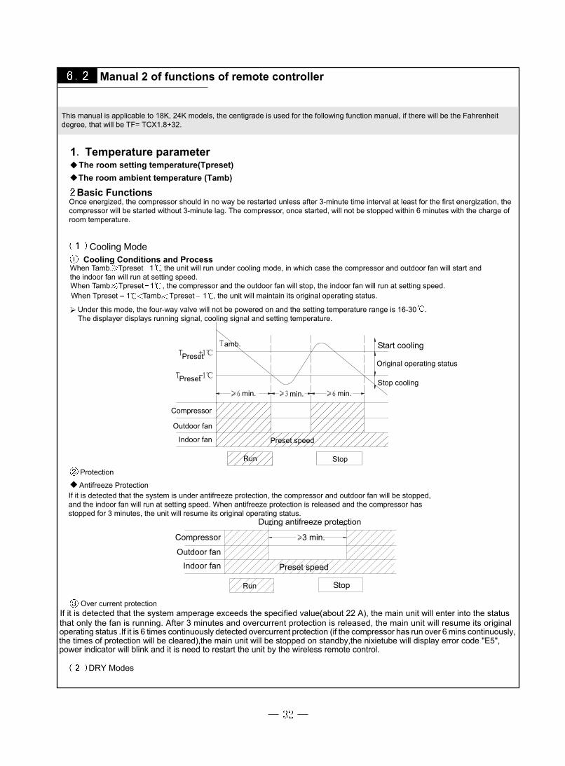
Manual 2 of functions of remote controller
1. Temperature parameterThe room setting temperature(Tpreset)The room ambient temperature (Tamb)
Basic Functions Once energized, the compressor should in no way be restarted unless after 3-minute time interval at least for the first energization, the compressor will be started without 3-minute lag. The compressor, once started, will not be stopped within 6 minutes with the charge ofroom temperature.
Cooling ModeCooling Conditions and Process
When Tamb. Tpreset 1 , the unit will run under cooling mode, in which case the compressor and outdoor fan will start andthe indoor fan will run at setting speed. When Tamb. Tpreset 1 , the compressor and the outdoor fan will stop, the indoor fan will run at setting speed.When Tpreset 1 Tamb. Tpreset 1 , the unit will maintain its original operating status.
Under this mode, the four-way valve will not be powered on and the setting temperature range is 16-30 .The displayer displays running signal, cooling signal and setting temperature.
Start cooling
Original operating status
Stop coolingmin. min. min.
Preset
Preset
amb.
Compressor
Outdoor fan
Indoor fan
Run Stop
Preset speed
Protection
Antifreeze ProtectionIf it is detected that the system is under antifreeze protection, the compressor and outdoor fan will be stopped,and the indoor fan will run at setting speed. When antifreeze protection is released and the compressor hasstopped for 3 minutes, the unit will resume its original operating status.
Compressor
Outdoor fan Indoor fan
Run Stop
During antifreeze protection
3 min.
Preset speed
Over current protection
DRY Modes
This manual is applicable to 18K, 24K models, the centigrade is used for the following function manual, if there will be the Fahrenheitdegree, that will be TF= TCX1.8+32.
If it is detected that the system amperage exceeds the specified value(about 22 A), the main unit will enter into the statusthat only the fan is running. After 3 minutes and overcurrent protection is released, the main unit will resume its original operating status .If it is 6 times continuously detected overcurrent protection (if the compressor has run over 6 mins continuously,the times of protection will be cleared),the main unit will be stopped on standby,the nixietube will display error code "E5",power indicator will blink and it is need to restart the unit by the wireless remote control.
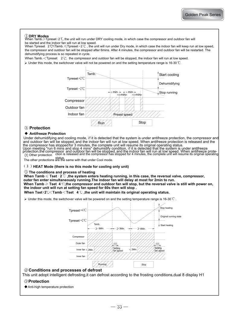
DRY ModesWhen Tamb. Tpreset 2 , the unit will run under DRY cooling mode, in which case the compressor and outdoor fan willbe started and the indoor fan will run at low speed.When Tpreset 2 Tamb. Tpreset 2 , the unit will run under Dry mode, in which case the indoor fan will keep run at low speed,the compressor and outdoor fan will be stopped after 6mins. After 4 minutes, the compressor and outdoor fan will be restarted. Thedehumidifying process is so repeated in cycle.When Tamb. Tpreset 2 , the compressor and outdoor fan will be stopped, the indoor fan will run at low speed.
Under this mode, the switchover valve will not be powered on and the setting temperature range is 16-30 .
Compressor
Outdoor fan
Indoor fan
Run Stop
Start cooling
Stop running
Preset speed
min. min. min. min.
Tpreset
TpresetTamb.
Dehumidifying
Protection Antifreeze Protection
HEAT Mode (there is no this mode for cooling only unit)The conditions and process of heating
When Tamb Tset 2 ,the system enters heating running, in this case, the reversal valve, compressor, outer fan enter simultaneously running.The indoor fan will delay at most for 2min to run.When Tamb Tset 4 ,the compressor and outdoor fan will stop, but the reversal valve is still with power on, the indoor unit will run at setting fan speed for 60s then will stop . When Tset 2 Tamb Tset 4 ,the unit will maintain its original operating status.
Under this mode, the switchover valve will be powered on and the setting temperature range is 16-30 .
Tpreset
TpresetTamb.
Compressor
Outer fan
Inner fan
Inner fan
Running Stop
6Min. 3Min. 6Min.
Stop heating
Original running state
Start heating
2Min. fan speedSetting 2Min. Setting
fan speed
Conditions and processes of defrostThis unit adopt intelligent defrosting,it can defrost according to the frosting conditions,dual 8 display H1
Protection Anti-high temperature protection
Other protectionThe other protections are the same with that under Cool mode.
Under dehumidifying and cooling mode, i f it is detected that the system is under antifreeze protection, the compressor andand outdoor fan will be stopped, and the indoor fan will run at low speed. When antifreeze protection is released and thethe compressor has stopped for 3 minutes, the complete unit will resume its original operating status.
Upon meeting "run 6 mins and stop 4 mins" dehumidify condition, i f it is detected that the system is under antifreezeprotection,the compressor and outdoor fan will be stopped, and the indoor fan will run at low speed. When antifreeze prote-
ction is released and the compressor has stopped for 4 minutes, the complete unit will resume its original operatingstatus.
Golden Peak Series

Other controlsTimer function
Ordinary Timer setting:timer on: Under unit off, the timer on function could be set up, if timer on has arrived, controller will run at setting mode, the timer interval is 0.5hr, setting range is 0.5-24hrs.Timer off: Under unit off, the timer off function could be set up, if timer off has arrived, controller will run at setting mode, the timer interval is 0.5hr, setting range is 0.5-24hrs.
Timer setting for hour:Timer on: if system is running, to set timer on, the system will continue to run, if unit is off to set up timer on,When timer on has arrived, the system will run at pressetting mode.Timer off: If system is off to set up the timer off, when to set up timer off, the unit will stand by, when unit is on,to set up timer off, when the timer off arrived, the system will stop to work.Timer setting change:When system is in Timer status, can set up timer on and timer off by wireless remote control, to reset up Timeralso, the system will run at last setting status.When system is running, at the same time to set up Timer on and Timer off, the system will keep the presentsetting status, when time arrived, system will stop to work.When system stop, at the same time to set up Timer on and Timer off, the system will stop, untile the timerarrived, the system will start to work.Hereafter, when timer of timer on in every day arrived, it will run the presetting modes, after timer off arrived,the system will stop.
Auto buttonAfter powered on, press this button, it will run at Auto mode, when repressed, the unit will turns off.
BuzzerThe controller is powered on and detect the signal received, the buzzer will beep.
Sleep functionUnder cooling or dehumidifying mode, the preset temperature will automatically rise by 1 , ine hour aftersetting of sleep program and rise by 1 after 2hours.
Under heating mode, the preset temperature will automatically decrease by 1 one hour after setting of sleepprogram and decrease by another 1 after 2hours.
Tpreset
Tpreset
Tpreset Preset temp. Tpreset
1hour 2hours 2hours above
Auto ModeUnder this mode, the system will automatically select its run mode (cool, dehumidify, heat or fan) with the change of ambient temperature. For protection function, same as under cooling and heating mode.
Fan mode Under FA N mode, only the indoor fan runs at setting speed.The RUN indicator will be bright. Double 8 module indicator will display the setting temperature. When stand by, the power indicator is bright but the unit does not run.
Noise Silencing ProtectionIf the unit is stopped by pressing ON/OFF, the reversal valve will be stopped after 2-minute l g; or 2 minutesa w l li be
delayed upon mode switching.
If it is detected that the evaporator tube temperature is too high, the outdoor fan will be stopped. When the tube temperature resumes to normal, the outdoor fan will be restarted.
Over current productThe overcurrent protection is the same with the the over current protection under cool mode.

Turbo functionThe turbo function is available in Cool and Heat modes.
Dry functionDry function is available in Cool and Dehumidifying modes.
Auto fan speed controlIn this mode, indoor fan can run with Hig, Mid, Low speeds.
Up and down swing control
DisplayerRunning figure and mode figure display
After powered on, the figure will be displayed, then only Power/running indicator turn on. When usingremote conroller to open the unit, it will turn on, at the same time to display current setting running modes.
Dual 8 display
PG motor lock protectionWhen turn on the fan motor, if motor continuously run for a while and the running speed is very slow, in orderto prevent motor automatically self-protection, it will stop running and display lock; If currently turns unit on,that dual 8 will display lock error code H6; If current is unit off, will not display the block error information.
After powered on, the lower swing motor will firstly rotate the guide louver to position 0, close up the air outletvent; After unit turned on, if to set up swing function, when indoor fan stop running, the guide louver will stopat current position, inner fan motor is running, guide louver will resume to swing.From Cool, Dry, Fan modes to Heat mode, the guide louver will be opened at D position, when turn on swing will run at (A-D); from Heatmode to Cool, Dry, Fan mode, the fan louver will turn to B position, if turn on the swing, it will run at (A-C).When unit is turned off, the guide louver will turn to position 0, the swing is only available after preset theswing function, and indoor unit is running. Note: When to set up at position L to B, A to C, B to D, the guide louver will swing between position W to D.
Tpreset
Tpreset
Tpreset
1hr. 2hrs. 2hrs. above
Tpreset temp.
Power-off MemoryMemory contents: Mode, UP/DOWN Swing, light, Set temp, Set fan speed.After de-energized, and re-energized, the unit will start to run with the memory function automatically. The system, if the last remote control signal do not set timer function, will memorize the last remote control signal and run according to it. If the last remote control signal has set timer function, the system is de-energized before the set time,when re-energized, the system will memorize the timer function, the set time will recalculate. If the last remote control signal has set timer function and thesystem is de-energized after the set time, when re-energized, the system will memorize the running status before de-energized.
When the unit is turned on, after powered on, the nixie tube will display the setting temp.(setting range is 16-30 ).When the preset temperature display signal has been received, the nixie tube will display the preset temperature;If the display ambient temperature signal has been received, the nixie tube will display the current indoor ambient
temperature, if to set up others by remote controller that the display will maintain its status. At displaying ambienttemperature, the unit received the remote control signal, it will display 5s preset temperature then turn to ambienttemperature display. The ambient temperature sensor malfunction will display F1; Indoor tube sensor will display
F2, wire jumper cap protection displays C5.
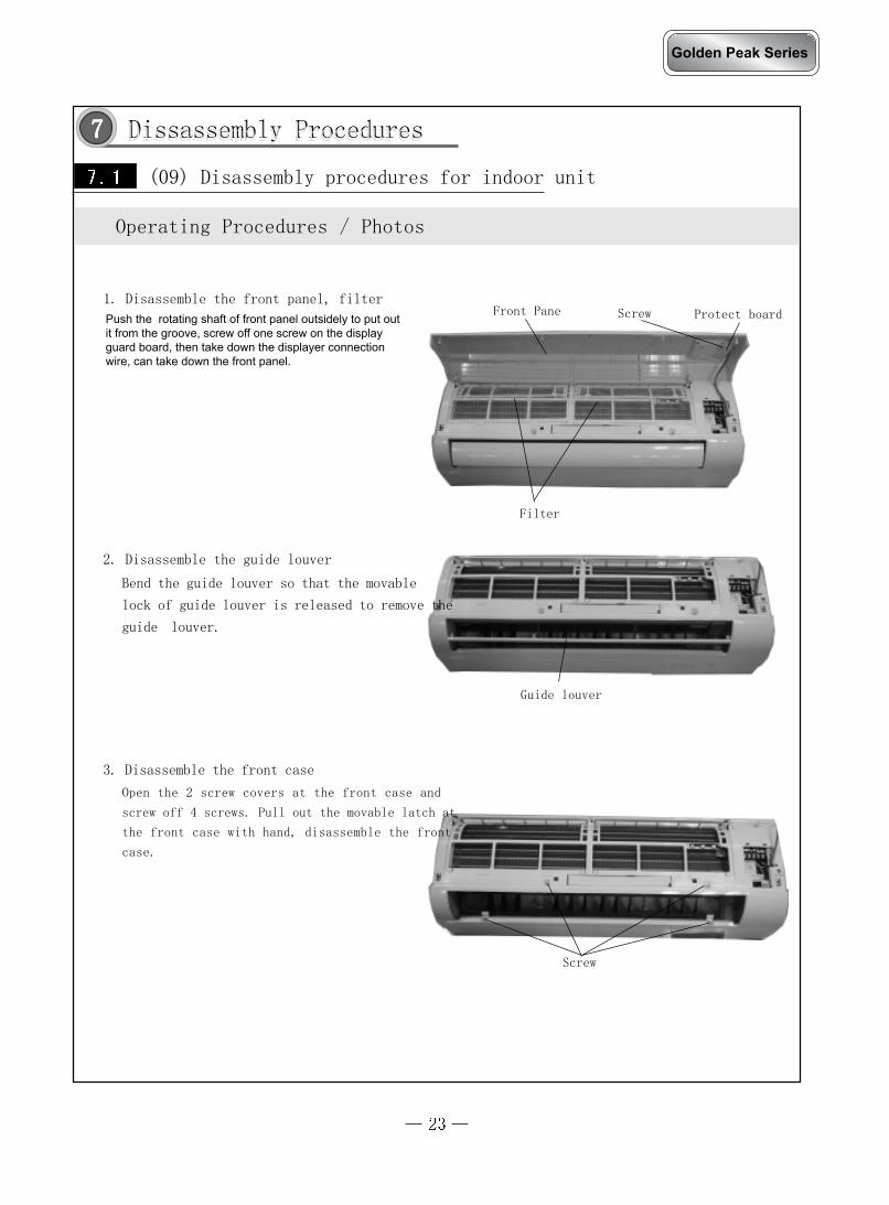
Dissassembly Procedures
Front Pane
(09) Disassembly procedures for indoor unit
1. Disassemble the front panel, filter
Filter
Bend the guide louver so that the movable
lock of guide louver is released to remove the
guide louver.
2. Disassemble the guide louver
Screw
Operating Procedures / Photos
Dissassembly Procedures77777
Screw
Guide louver
Open the 2 screw covers at the front case and
screw off 4 screws. Pull out the movable latch at
the front case with hand, disassemble the front
case.
3. Disassemble the front case
Protect board
Golden Peak Series
Push the rotating shaft of front panel outsidely to put outit from the groove, screw off one screw on the displayguard board, then take down the displayer connectionwire, can take down the front panel.
Operating Procedures / Photos
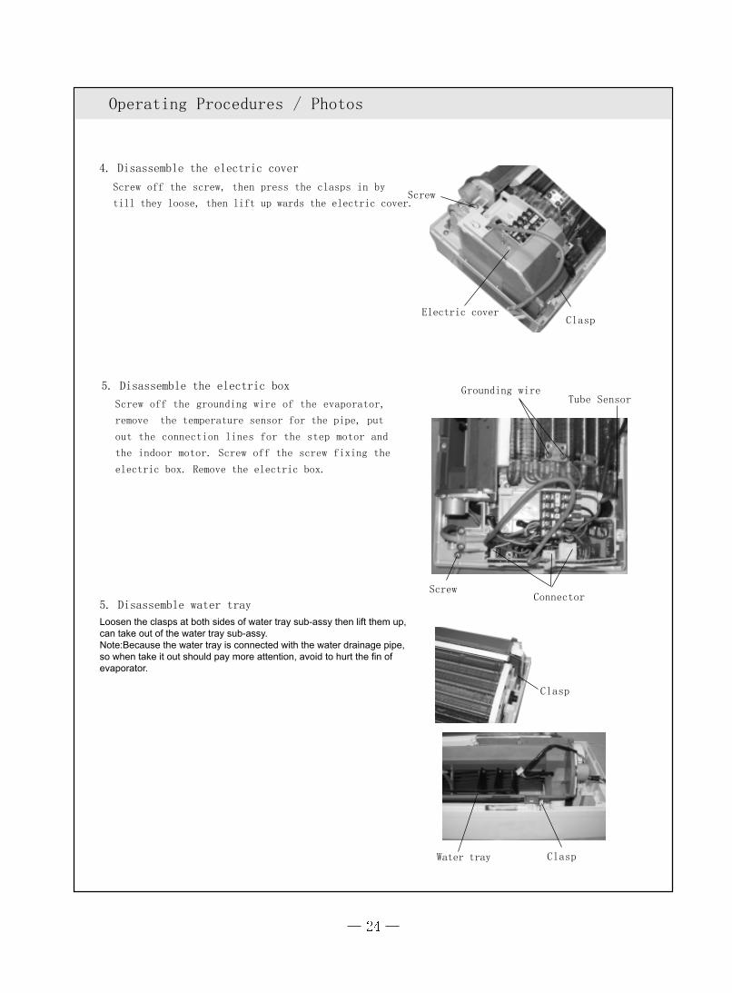
Screw off the screw, then press the clasps in by
till they loose, then lift up wards the electric cover.
4. Disassemble the electric cover
5. Disassemble water tray
Electric cover
5. Disassemble the electric box
Screw off the grounding wire of the evaporator,
remove the temperature sensor for the pipe, put
out the connection lines for the step motor and
the indoor motor. Screw off the screw fixing the
electric box. Remove the electric box.
Grounding wire
Connector
Tube Sensor
Clasp
Clasp
Water tray
Screw
Clasp
Screw
Loosen the clasps at both sides of water tray sub-assy then lift them up,can take out of the water tray sub-assy.Note:Because the water tray is connected with the water drainage pipe,so when take it out should pay more attention, avoid to hurt the fin of evaporator.

Operating Procedures / Photos
Screw off 4 screws fixing the motor cover and then
take the motor cover out.
Screw off the holding screw at the left shaft sleeve
of the cross flow fan, pull out the motor, and re-
move the cross flow fan.
7. Disassembling motor and cross flow fan
6. Disassembling the evaporator
Screws
CAUTION:When repair, Carefully take out the evaporator and
pay attention to protect the connecting pipe.
Screws
Motor Press Plate
Screws
Screw
Golden Peak Series
Screw off one screw which fix the connection pipe clamp.Take off the connection pipe clamp.

Open the front panel ,Push the filter upwards tounloose the clasp, and then pull out the two filters.
Front Pane
(12) Disassembly procedures for indoor unit
1. Disassemble the front panel, filter
Filter
Bend the guide louver so that the movable
lock of guide louver is released to remove the
guide louver.
2. Disassemble the guide louver
Screw
Operating Procedures / Photos
Screw
Guide louver
Open the 2 screw covers at the front case and
screw off 4 screws. Pull out the movable latch at
the front case with hand and then pull it back-
wards to disassemble the front case.
3. Disassemble the front case
Display Cover
Screw off one screw on the displayerbox, take down the guard board thendisconnect the displayer connection wire, can take down the front panel.
Operating Procedures / Photos
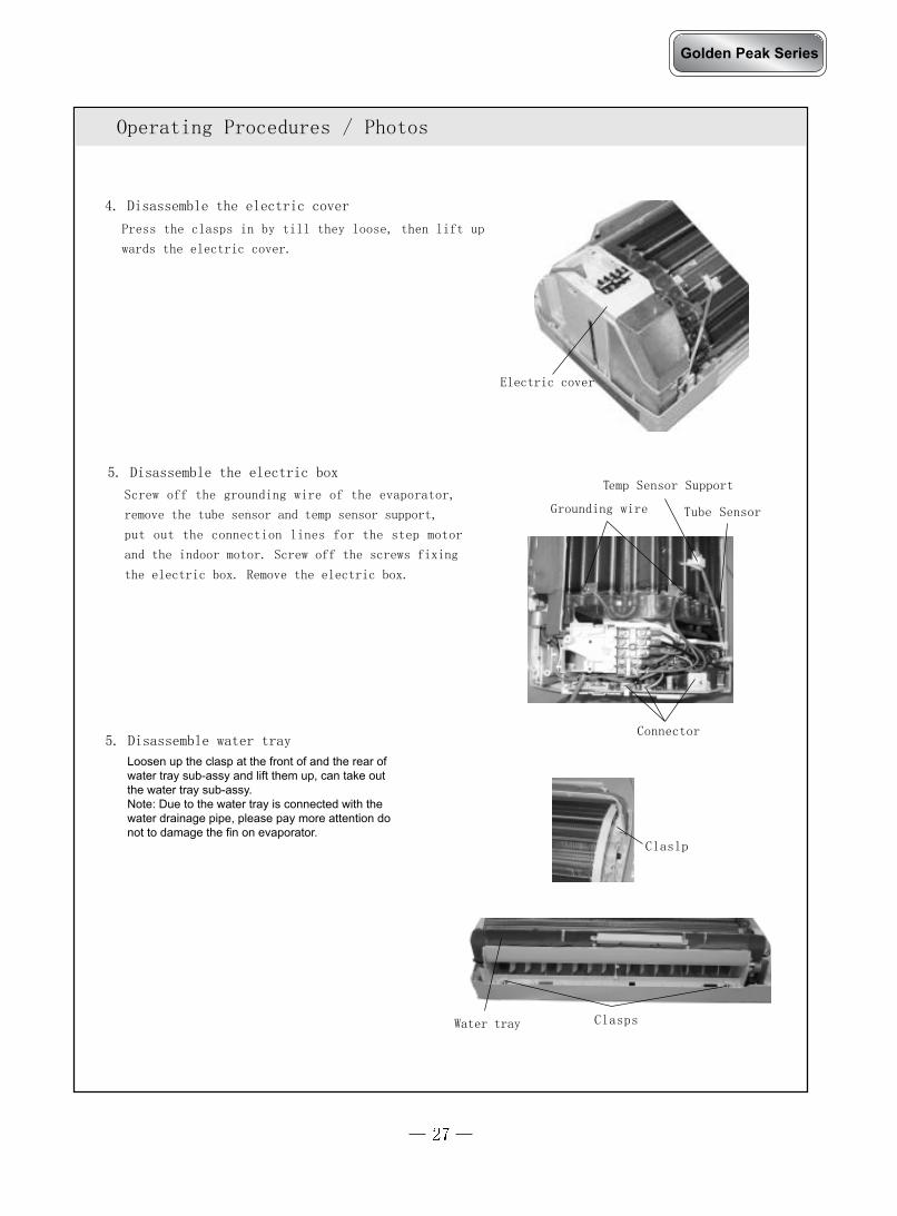
Press the clasps in by till they loose, then lift up
wards the electric cover.
4. Disassemble the electric cover
5. Disassemble water tray
Electric cover
5. Disassemble the electric box
Screw off the grounding wire of the evaporator,
remove the tube sensor and temp sensor support,
put out the connection lines for the step motor
and the indoor motor. Screw off the screws fixing
the electric box. Remove the electric box.
Grounding wire
Connector
Tube Sensor
Temp Sensor Support
Clasps
Claslp
Water tray
Golden Peak Series
Loosen up the clasp at the front of and the rear ofwater tray sub-assy and lift them up, can take outthe water tray sub-assy.Note: Due to the water tray is connected with thewater drainage pipe, please pay more attention do not to damage the fin on evaporator.

Operating Procedures / Photos
Screw off 4 screws fixing the motor cover and then
take the motor cover out.
Screw off the holding screw at the left shaft sleeve
of the cross flow fan, pull out the motor, and re-
move the cross flow fan.
Screw off 4 screws fixing the left and right side of
the evaporator, then elevate left side the evapora-
tor to remove it backward.
7. Disassembling motor and cross flow fan
6. Disassembling the evaporator
Screws
CAUTION:When repair, Carefully take out the evaporator and
pay attention to protect the connecting pipe.
Screws
Motor Press Plate
Screws
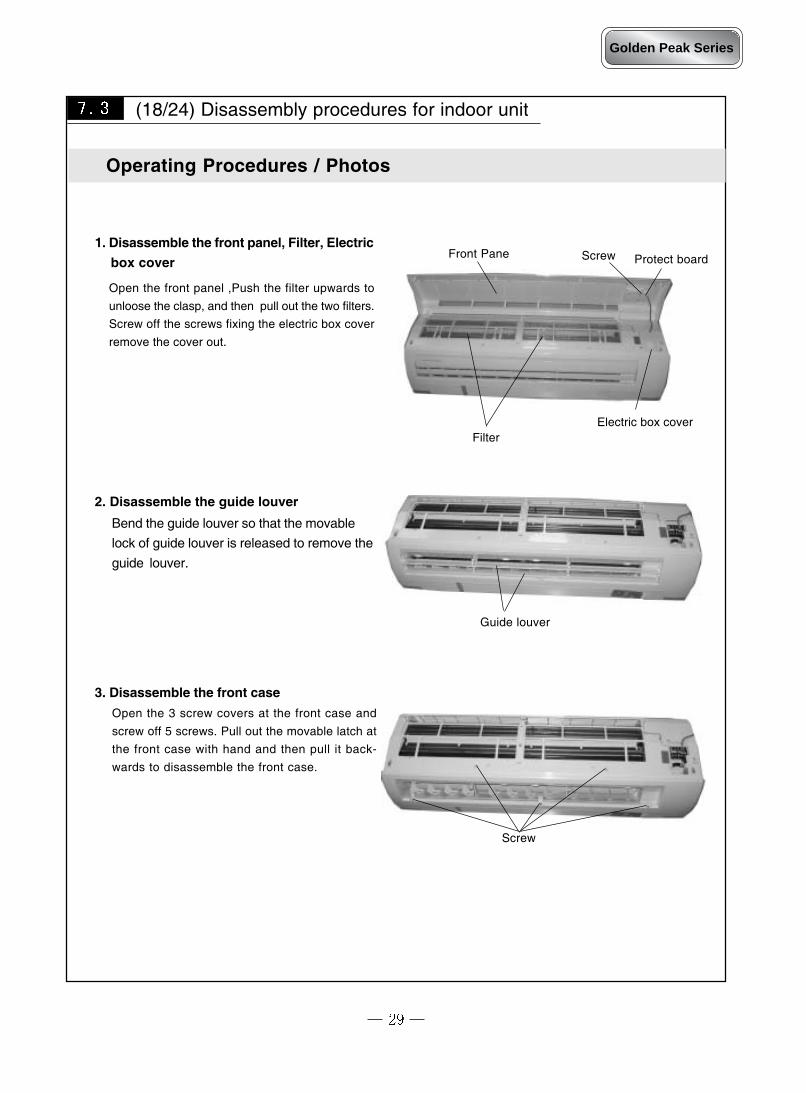
Open the front panel ,Push the filter upwards to
unloose the clasp, and then pull out the two filters.
Screw off the screws fixing the electric box cover
remove the cover out.
Front Pane
(18/24) Disassembly procedures for indoor unit
1. Disassemble the front panel, Filter, Electric
box cover
Filter
Bend the guide louver so that the movable
lock of guide louver is released to remove the
guide louver.
2. Disassemble the guide louver
Screw
Operating Procedures / Photos
Screw Protect board
Guide louver
Open the 3 screw covers at the front case and
screw off 5 screws. Pull out the movable latch at
the front case with hand and then pull it back-
wards to disassemble the front case.
3. Disassemble the front case
Electric box cover
Golden Peak Series
Operating Procedures / Photos
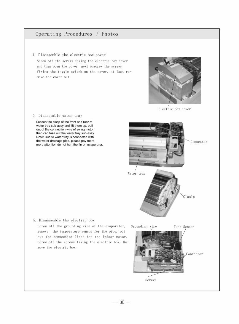
Screw off the screws fixing the electric box cover
and then open the cover, next unscrew the screws
fixing the toggle switch on the cover, at last re-
move the cover out.
4. Disassemble the electric box cover
5. Disassemble water tray
Electric box cover
5. Disassemble the electric box
Screw off the grounding wire of the evaporator,
remove the temperature sensor for the pipe, put
out the connection lines for the indoor motor.
Screw off the screws fixing the electric box. Re-
move the electric box.
Grounding wire
Connector
Claslp
Water tray
Connector
Tube Sensor
Screws
Loosen the clasp of the front and rear ofwater tray sub-assy and lift them up, pullout of the connection wire of swing motor,then can take out the water tray sub-assy.Note: Due to water tray is connected with the water drainage pipe, please pay moremore attention do not hurt the fin on evaporator.

Screw Motor
Cross flow fan
Operating Procedures / Photos
Screw off 4 screws fixing the motor cover and then
take the motor cover out.
Screw off the screw connecting the cross flow fan
and motor, then pull out the motor and remove
the cross flow fan.
Screw off 5 screws fixing the left and right side of
the evaporator, then elevate left side the evapora-
tor to remove it backward.
7. Disassembling motor and cross flow fan
6. Disassembling the evaporator
Screws
CAUTION:
When repair, Carefully take out the evaporator and
pay attention to protect the connecting pipe.
Screws
Motor Press Plate
Screw
Golden Peak Series
Screw off one screw which fix the connection board clamp.Take down the connection board clamp.

Push the rotating shaft of front panel outwards to
unloose the clasp, and then pull out the front panel.
Front Panel
(Conventional 09) Disassembly procedures for indoor unit
1. Disassemble the front panel, filter
Filter
Bend the guide louver so that the movable
lock of guide louver is released to remove the
guide louver.
2. Disassemble the guide louver
Screws
Operating Procedures / Photos
Screw
Guide louver
Open the 2 screw covers at the front case and
screw off 4 screws. Pull out the movable latch at
the front case with hand and then pull it back-
wards to disassemble the front case.
3. Disassemble the front case
Electric Box Cover
Screw off the screws of the electric box cover,and take down the electric box cover.
Golden Peak Series

Operating Procedures / Photos
Screw off the screw, then press the clasps in by
till they loose, then lift up wards the electric cover
and the light board.
4. Disassemble the electric box cover
5. Disassemble water tray
Electric box cover
6. Disassemble the electric boxLoosen the grounding wire of the evaporator, re-
move the temperature sensor for the pipe, put
out the connection lines for the indoor motor.
Screw off the screws fixing the electric box. Re-
move the electric box.
Grounding wire
Connector
Claslp
Water tray
Connector
Tube Sensor
Screw
Screw
Light Board
Loosen up the clasp at the front of and the rear of
water tray sub-assy and lift them up, can take out
the water tray sub-assy.
Note: Due to the water tray is connected with the
water drainage pipe, please pay more attention do
not to damage the fin on evaporator.

Operating Procedures / Photos
Screw off 4 screws fixing the motor cover and then
take the motor cover out.
Screw off the holding screw at the left shaft sleeve
of the cross flow fan, pull out the motor, and re-
move the cross flow fan.
8. Disassembling motor and cross flow fan
7. Disassembling the evaporator
Screws
CAUTION:When repair, Carefully take out the evaporator and
pay attention to protect the connecting pipe.
Screws
Motor Press Plate
Screw
ScrewScrew off 1 pc screw fixing the connecting pipeclamp, take down the connecting pipe clamp.
Golden Peak Series