1 themis-scm thm-scm-cdr – 2004.04.08bertrand delaporte thm – scm – cdr – 08-april-2004 in...
TRANSCRIPT
1
THEMIS-SCM
THM-SCM-CDR – 2004.04.08Bertrand delaPorte
THM – SCM – CDR – 08-April-2004 in Velizy
• Test and Calibration Plan
• I&T Plans prior to shipment to UCB
• EGSE Design
• I&T and Spacecraft Integration Plans
• Implementation Schedule
2THM-SCM-CDR – 2004.04.08
THEMIS-SCM
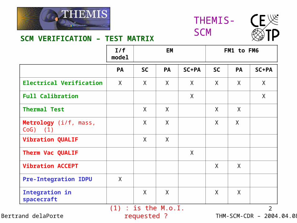
SCM VERIFICATION – TEST MATRIX
PA SC PA SC+PA SC PA SC+PA
Electrical Verification X X X X X X X
Full Calibration X X
Thermal Test X X X X
Metrology (i/f, mass, CoG) (1) X X X X
Vibration QUALIF X X
Therm Vac QUALIF X
Vibration ACCEPT X X
Pre-Integration IDPU X
Integration in spacecraft X X X X
I/f model
EM FM1 to FM6
Bertrand delaPorte(1) : is the M.o.I. requested ?
3
THEMIS-SCM
THM-SCM-CDR – 2004.04.08Bertrand delaPorte
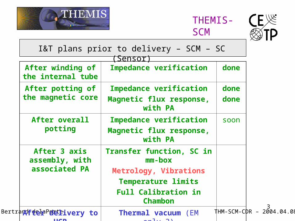
After winding of the internal tube
Impedance verification done
After potting of the magnetic core
Impedance verification
Magnetic flux response, with PA
done
done
After overall potting Impedance verification
Magnetic flux response, with PA
soon
After 3 axis assembly, with associated PA
Transfer function, SC in mm-box
Metrology, Vibrations
Temperature limits
Full Calibration in Chambon
After delivery to UCB Thermal vacuum (EM only ?)
I&T plans prior to delivery – SCM – SC (Sensor)
4
THEMIS-SCM
THM-SCM-CDR – 2004.04.08Bertrand delaPorte
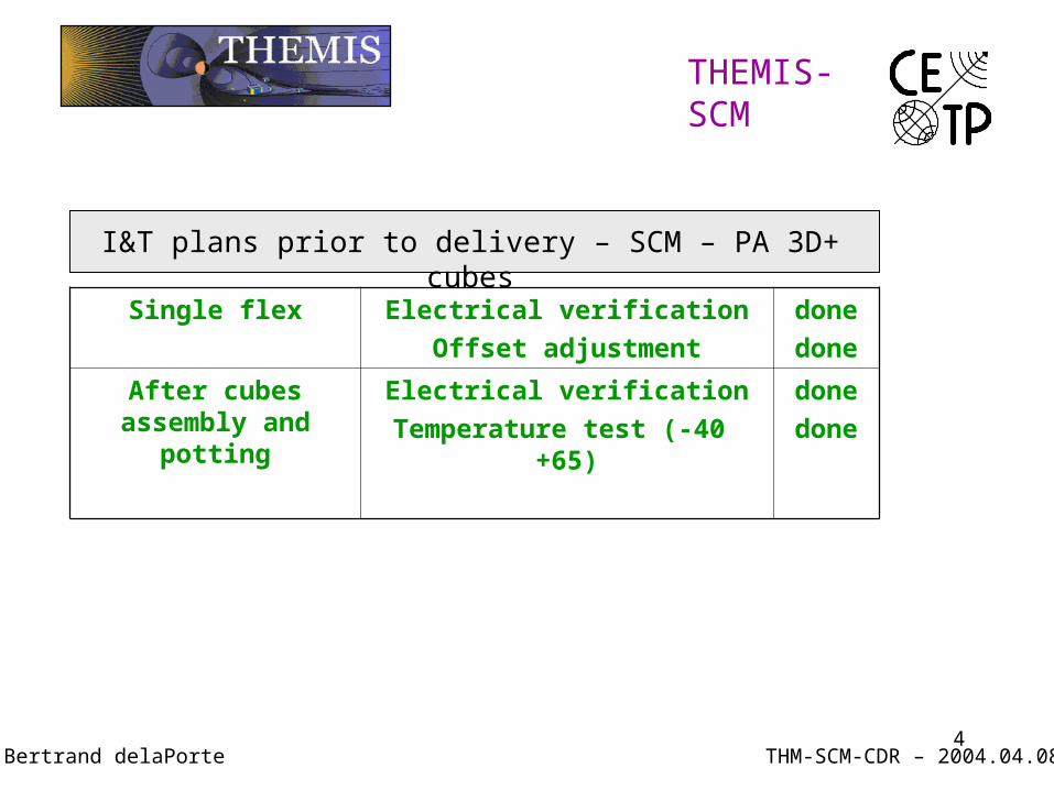
Single flex Electrical verification
Offset adjustment
done
done
After cubes assembly and potting
Electrical verification
Temperature test (-40 +65)
done
done
I&T plans prior to delivery – SCM – PA 3D+ cubes
5
THEMIS-SCM
THM-SCM-CDR – 2004.04.08Bertrand delaPorte
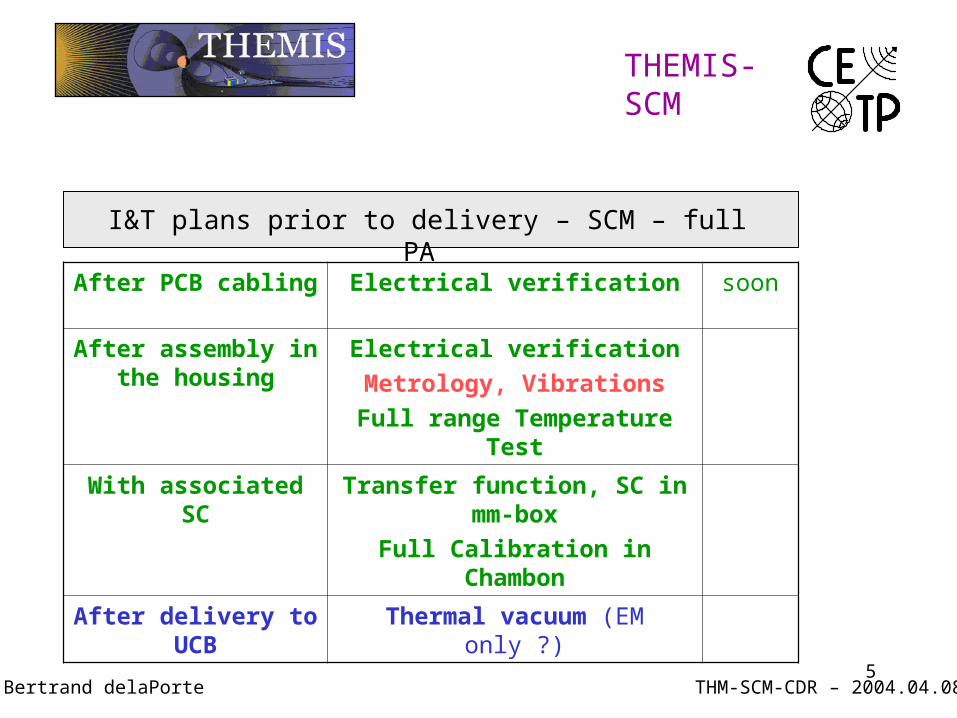
After PCB cabling Electrical verification soon
After assembly in the housing
Electrical verification
Metrology, Vibrations
Full range Temperature Test
With associated SC Transfer function, SC in mm-box
Full Calibration in Chambon
After delivery to UCB Thermal vacuum (EM only ?)
I&T plans prior to delivery – SCM – full PA
6THM-SCM-CDR – 2004.04.08
THEMIS-SCM
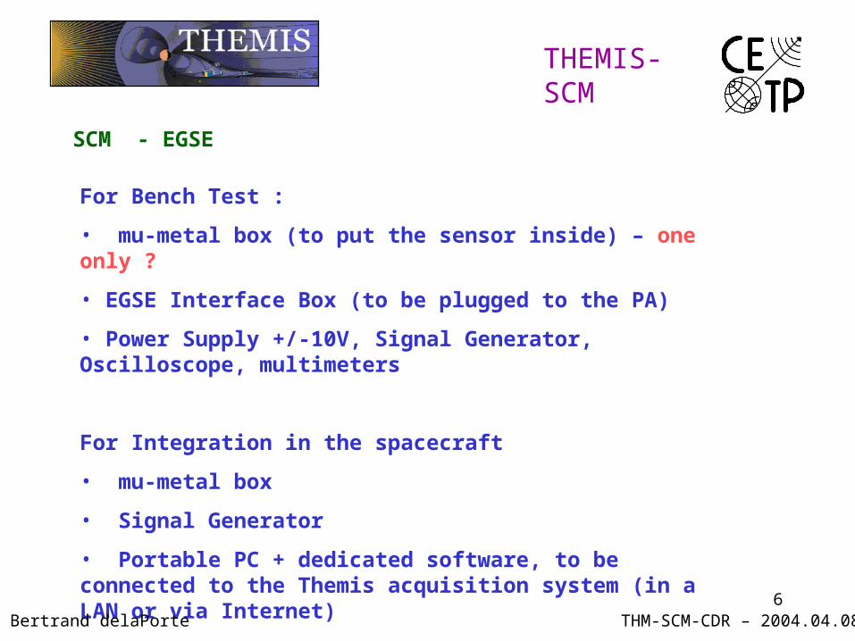
SCM - EGSE
For Bench Test :
• mu-metal box (to put the sensor inside) – one only ?
• EGSE Interface Box (to be plugged to the PA)
• Power Supply +/-10V, Signal Generator, Oscilloscope, multimeters
For Integration in the spacecraft
• mu-metal box
• Signal Generator
• Portable PC + dedicated software, to be connected to the Themis acquisition system (in a LAN or via Internet)
Bertrand delaPorte

7
THEMIS-SCM
THM-SCM-CDR – 2004.04.08Bertrand delaPorte
SCM Bench Test Configuration
8
THEMIS-SCM
THM-SCM-CDR – 2004.04.08
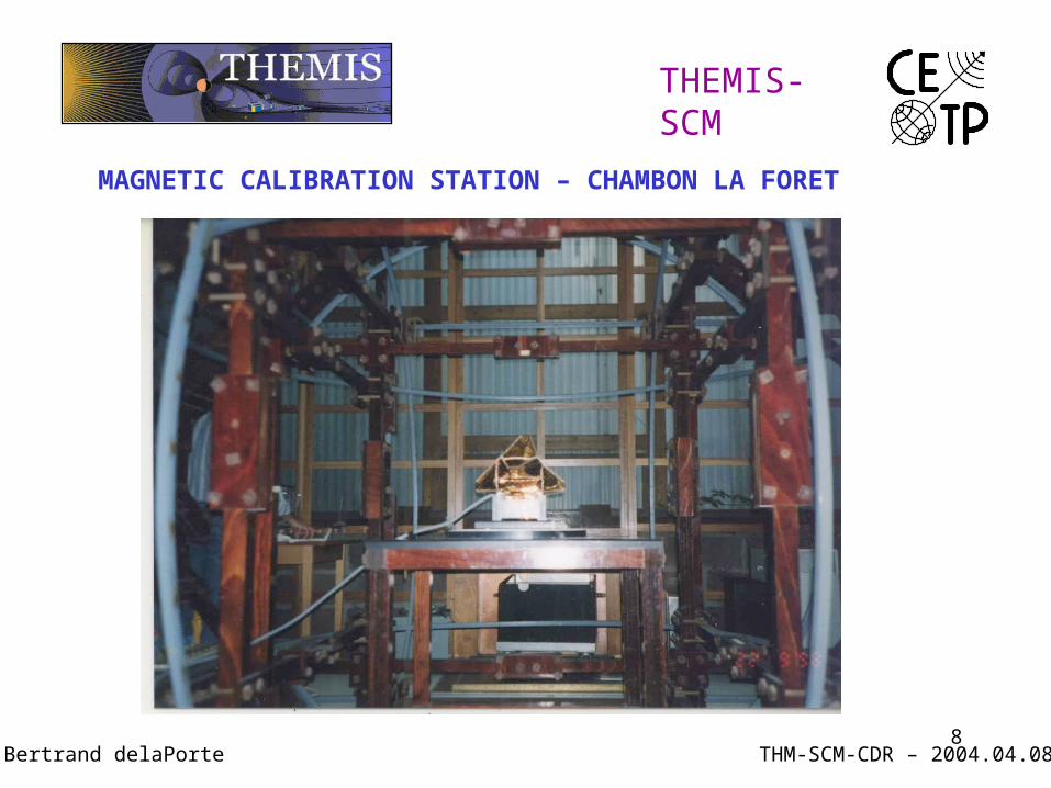
MAGNETIC CALIBRATION STATION – CHAMBON LA FORET
Bertrand delaPorte
9
THEMIS-SCM
THM-SCM-CDR – 2004.04.08Bertrand delaPorte
I&T AND SPACECRAFT INTEGRATION PLAN
1. Pre-intégration SCM – IDPU (DFB)
2. Integration to the spacecraft
10THM-SCM-CDR – 2004.04.08
THEMIS-SCM
1. Pre-Integration with IDPU
An « Interface Model » of the Pre-Amp will be provided for that purpose
• Same Power, Command, analog output interfaces
• Power and Cal Mode identification by led
• Cal Signal re-injected to the input
• A signal generator can be connected to each input
Validation can only be done by analysis of the telemetry data (tbd)
Bertrand delaPorte
I&T AND SPACECRAFT INTEGRATION PLAN
11THM-SCM-CDR – 2004.04.08
THEMIS-SCM
2. Integration in the spacecraft
• Delivery (Incoming Inspection, Bench Test)
• Mechanical Integration of the PA, connection to the boom harness
• Sensor in the mu-metal box, connection to the boom harness
• Electrical Integration (bounding, isolation, dangerous voltage)
• Power ON and functionnal Test
Validation can only be done by analysis of the telemetry data (tbd)
Bertrand delaPorte
I&T AND SPACECRAFT INTEGRATION PLAN
12
THEMIS-SCM
THM-SCM-CDR – 2004.04.08Bertrand delaPorte
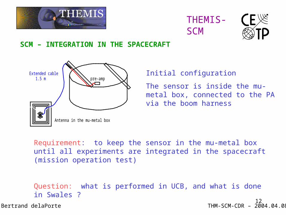
Extended cable 1.5 m
Antenna in the mu-metal box
pre-amp
SCM – INTEGRATION IN THE SPACECRAFT
Initial configuration
The sensor is inside the mu-metal box, connected to the PA via the boom harness
Requirement: to keep the sensor in the mu-metal box until all experiments are integrated in the spacecraft (mission operation test)
Question: what is performed in UCB, and what is done in Swales ?
13
THEMIS-SCM
THM-SCM-CDR – 2004.04.08Bertrand delaPorte
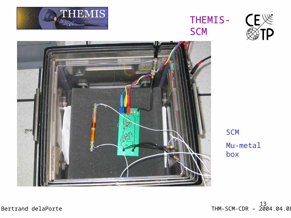
SCM
Mu-metal box
14
THEMIS-SCM
THM-SCM-CDR – 2004.04.08Bertrand delaPorte
SCM – INTEGRATION IN THE SPACECRAFT
WHAT CAN BE DONE WITH THE SENSOR IN THE MU-METAL BOX
• axis identification
• re-verification of the end-to-end calibration
• Phase relation within the 3 components (for the waveforms)
• check of the conducted noise
• SCM/EField timing reference [and inter-calibration] (tbd)
15
THEMIS-SCM
THM-SCM-CDR – 2004.04.08Bertrand delaPorte
SCM – INTEGRATION IN THE SPACECRAFT
SENSOR MOUNTED ON THE BOOM
• PA saturated by the 50/60 Hz
except in a quite site (i.e. Chambon), or in an EMC chamber
• No measurement possible but a big failure would be seen
INSTALLATION OF THE MLI - by UCB when ?
16THM-SCM-PDR – 2003.10.10
THEMIS-SCM
SCM – INTEGRATION – QUICK TESTS WITH HOUSEKEEPING
A few Housekeeping are needed to check the experiment rapidly (if possible in real time) during the ground tests and in the commissioning.
HOUSEKEEPING FOR SCM:
• SCM-PWR-STATUS ( 1 bit )
• SCM-CAL-STATUS ( 1 bit )
• SCM-VOLT-MONITOR ( 8 bits )
• SCM-MEAN-VAL-BX, __BY, __BZ ( 16 or 8 bits )
Mean average of |Bi| over one TM format (similar to r.m.s. value)
Bertrand delaPorte
17
THEMIS-SCM
THM-SCM-CDR – 2004.04.08Bertrand delaPorte
AC MAGNETIC NOISE VERIFICATION
In the low frequency range (< 4 kHz), the main sources of AC noise are
• The beating within several higher frequencies, especially the DC/DC Converters if they are not synchronised. It can be conducted and/or radiated.
• The solar pannels (cannot be verified on the ground)
The CETP can help to analyse the AC radiated noise around the spacecraft. A « magnetic sniffer » has been designed and built for that purpose. In order to avoid the saturation by the 50/60 Hz, the analysis is separated into two bandwidths: below 50 Hz and above 300 Hz (5th harmonic)

18THM-SCM-CDR – 2004.04.08
THEMIS-SCM
SCM INTEGRATION – TEAM SUPPORT
The SCM team will support all critical activities of the integrations.
However, due to the large number of satellites, a strategy must be imagined to limit the number of travels, the cost and the time spent
The EM integration will be supported
The FM will be delivered 3 by 3 and the level of support for each test will be agreed with UCB
Capability of remote supporting should be implemented
Bertrand delaPorte
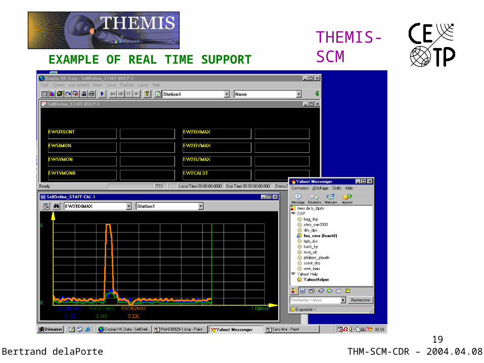
19
THEMIS-SCM
THM-SCM-CDR – 2004.04.08
EXAMPLE OF REAL TIME SUPPORT
Bertrand delaPorte
20
THEMIS-SCM
THM-SCM-CDR – 2004.04.08Bertrand delaPorte
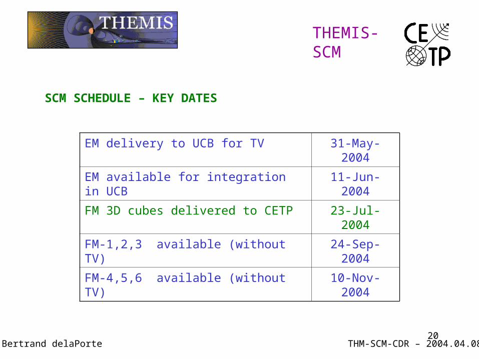
SCM SCHEDULE – KEY DATES
EM delivery to UCB for TV 31-May-2004
EM available for integration in UCB 11-Jun-2004
FM 3D cubes delivered to CETP 23-Jul-2004
FM-1,2,3 available (without TV) 24-Sep-2004
FM-4,5,6 available (without TV) 10-Nov-2004
21
22
23
THEMIS-SCM
THM-SCM-CDR – 2004.04.08Bertrand delaPorte