1 twepp 2007, prague - 07 sepl.guiducci - infn bologna dt sector collector electronics design and...
TRANSCRIPT

TWEPP 2007, Prague - 07 SepL.Guiducci - INFN Bologna 1
DT Sector Collector Electronics
Design and Construction
Luigi Guiducci
M. Dallavalle, A. Montanari, F. Odorici,
G. Pellegrini, G. Torromeo, R. Travaglini
Università di Bologna e INFN Sezione di Bologna
TWEPP 2007Prague, Czech Republic

TWEPP 2007, Prague - 07 SepL.Guiducci - INFN Bologna 2
Outline
• Introduction• CMS muon detectors and DT Trigger overview• DT Trigger Sector Collector main tasks and requirements• Radiation issues and flash-based FPGAs choice
• DT Sector Collector hardware description• Trigger data path• Control and monitoring interfaces• Main firmwares features
• Hardware production tests• Screening tests• Full I/O, 40 MHz complete tests
• Experience from commissioning• Synchronization tools• Spy data for trigger synchronization control

TWEPP 2007, Prague - 07 SepL.Guiducci - INFN Bologna 3
CMS Drift Tubes Muon Detectors
• 2 Superlayers in the φ view, 1 in the θ view (SL = 4 planes of DTs)• Maximum drift distance in the cell ~ 2 cm ≈ 400 ns = 16 BX
250 DT chambers in 4 concentrical stations, in 30° sectors, in 5 wheelsUse of field in the yoke (~ 2T) for stand-alone Pt determination
WHEEL (5)
CHAMBER (250)
CELL (~ 176k)

TWEPP 2007, Prague - 07 SepL.Guiducci - INFN Bologna 4
DT Local Trigger• Made of ~ 55000 ASICs
• Minicrates mounted on DTCs for both trigger and readout HW
• Trigger Outputs/BX:-2 φ-view track segments (bits): position (12), bending (10), reconstruction quality (3)- θ-view hits- 30 BX latency (16 BX drift time)
• Trigger links:2 x FTP cablesmaximum length 40 m8 LVDS links @ 480 Mb/s
TS removes ghosts and select 2 “best” muons/BX
TRACO correlates segments from the 2 φ SL
BTI finds alignment of hits,assigns BX, φ, φb

TWEPP 2007, Prague - 07 SepL.Guiducci - INFN Bologna 5
ME
/1/3
2- 1
MB1
MB2
MB3
MB4
extrapolation window
track segments
muon path
IP
DT Regional Trigger - Track Finder (DTTF)
• FPGA-based system in underground counting room• Input: track segments from the detector via Opto links• Extrapolation method to correlate track segments in the r-φ view and assign Pt from the bending• Pattern matching method in the η view (straight tracks)• For the DTTF, the input trigger data from all chambers must be synchronized at the same BX
θ view
Φ view

TWEPP 2007, Prague - 07 SepL.Guiducci - INFN Bologna 6
LVDSOPTO
Sector Collector: location and main tasks
• Located on detector towers, 60 SC boards (1/DT 30° sector), 2 VME 9U crates / wheel
Main tasks:• Synchronization of sector links• Sorting of track segments candidates• Monitoring of data• Sector-level trigger generation and distribution• Local trigger data sent on optical fibers to the underground counting room Sector Collector crates
VME 9U with custom J3 backplane

TWEPP 2007, Prague - 07 SepL.Guiducci - INFN Bologna 7
Radiation tolerance
In experimental cavern, outside the magnet yoke• Neutron fluxes around CMS barrel are ~ 0.1—1 kHz/cm2 for E > 100 keV• Very low damage to electronics, but single event effects must be considered• Memory cells can flip state FPGAs configuration memory can be corrupted by SEE
ExperimentalHall
Flash cells are more robust than SRAM cells (~15 V for programming, smaller)
FLASH
SRAM
Near-detector towers: ProAsicPlus FPGA from Actel• Configuration memory is FLASH-based
Counting room: Altera StratixGX FPGA• with 8 embedded gigabit transceivers
Underground Counting Room

TWEPP 2007, Prague - 07 SepL.Guiducci - INFN Bologna 8
Sector Collector – ImplementationInput links
Cat-5 FTP cables(480 Mb/s LVDS)from the minicrate
Output linksOptical fibers
• 9U motherboard: hosts RX/TX piggy boards, VME, TTC/Readout • LVDS-RX mezzanines with 480 Mb/s deserializers and FPGA• OptoTX mezzanine with 6 GOL chips at 1.6 Gb/s• OptoRX boards (at DTTF crates) with deserializer FPGA
Opto-RX
VME
TTC

TWEPP 2007, Prague - 07 SepL.Guiducci - INFN Bologna 9
LVDS Receiver mezzanineTr
igge
r dat
a fr
om o
ne c
ham
ber @
480
Mb/
s
Cable equalizers CLC014
Deserializers DS92LV1212Actel ProAsic+300
BGA 456 balls
Trigger data to OptoTX Spy and status datato board control device
JTAG Interface(programming, spy,
status, configuration)
I2C interface(temperature sensor)
Firmware main features: 4-to-1 segments sorting, I/O spy with 256 BX deep buffers (JTAG), test patterns generation, channel masking, output pipe for coarse delay adjustment

TWEPP 2007, Prague - 07 SepL.Guiducci - INFN Bologna 10
Sector Collector – Trigger data paths• Each LVDS receiver mezzanine delivers full trigger data to the Optical Transmitter mezzanine

TWEPP 2007, Prague - 07 SepL.Guiducci - INFN Bologna 11
Sector Collector – Trigger data paths
Spy Data
• Each LVDS receiver mezzanine delivers full trigger data to the Optical Transmitter mezzanine
• A partial copy of the trigger info (quality of the track segment, theta hits, bunch counters, parity checks, etc) is sent to the control chip at every bunch crossing

TWEPP 2007, Prague - 07 SepL.Guiducci - INFN Bologna 12
Sector Collector – Trigger data paths
Spy Data
• Each LVDS receiver mezzanine delivers full trigger data to the Optical Transmitter mezzanine
• A partial copy of the trigger info (quality of the track segment, theta hits, bunch counters, parity checks, etc) is sent to the control chip at every bunch crossing
• The control chip includes RAM-based buffers which can spy the track segments and their timing. These data can be accessed through VME or injected into the event data with a dedicated connection to the readout boards
to R
EA
DO
UT
VME A
cces
s

TWEPP 2007, Prague - 07 SepL.Guiducci - INFN Bologna 13
Sector Collector – Local trigger generation
• Spy information can be used to generate a local trigger signal
• Logic function of triggers from the single chambers (coincidence, OR, anti-coincid...)
• These “local trigger” signals are sent in LVDS to sector chambers and to near ROS (DAQ) board
• In this way a local (sector-wide) trigger system is implemented

TWEPP 2007, Prague - 07 SepL.Guiducci - INFN Bologna 14
Sector Collector – Jtag and I2C interfaces• JTAG chain connects RX FPGAs
• Controlled through VME - Via Control Chip (1) - Via VME-JTAG bridge (2)
• Remote firmware upgrade• Boundary scan• Access to detailed RX status and control registers• Access to RX spy buffers (full I/O x 256 BXs) allows a full minicrate trigger test
• I2C interface• Controlled through VME• Access to temperature / current / voltages sensors• Access to GOL chips configuration and status
(1)(2)

TWEPP 2007, Prague - 07 SepL.Guiducci - INFN Bologna 15
Optical Transmitter Mezzanine
GOL chips @ 1.6 Gb/sClock buffer NB100LVEP221FA
QPLL & crystal
VCSELs HFE4190-541 (850 nm) Trigger data from LVDS-RX(6x32 bit @ 40 MHz)
Loca
l trig
ger d
ata
6 x
1.6
Gb/
s
I2C Interface(temperature, GOL bias current, laser monitoring)
JTAG Interface(boudary scan)

TWEPP 2007, Prague - 07 SepL.Guiducci - INFN Bologna 16
Optical Receiver board
Loca
l trig
ger d
ata
@ 1
.6 G
b/s
Altera StratixGX – BGA 672 balls
CMOS drivers (backplane fanout)
To D
TTF
@ 4
0 M
Hz
JTAG interface (config / status / boundary scan /FPGA programming)
Firmware main features:
• Phi and Eta versions
• Embedded deserializers (4 or 5) 1.6 Gb/s 40 MHz
• Test patterns generation
• Per-channel output pipe for synchronization (up to 3 BXs in 6.25ns steps)
• Automatic check of test patterns sent by GOLs (allows > 1011 patterns/hour)
• Custom JTAG chain for configuration, status (link unlocks, parity errors, etc)
Amplifiers SY88883

TWEPP 2007, Prague - 07 SepL.Guiducci - INFN Bologna 17
Optical link monitoring and control
GOL
ADC
TEMP
VCSEL
SY88883RX FPGA
I2C CTRL
VME FPGA
Control PC
DTTF BoardVME to JTAG
BridgeControl PC
PIN
I2C
JTAG
Check amplifier threshold conditionCheck RX frequency lockCheck RX data paritiesCheck GOL test patterns
Set GOL bias currentSet/Unset GOL testmodeMeasure emitted lightMeasure temperature
Software world
Track Segments fromLocal Trigger
Track segments to DT Track Finder
TCP/IP

TWEPP 2007, Prague - 07 SepL.Guiducci - INFN Bologna 18
Tests/1 - Screening
BOARDS: opto-tx lvds2ch
Tested @ producer
Piggy screening tests:Power & verify connectivityvia JTAG boundary scan
StaticPatterns
(on “inputs”)
LVDS-TX
JTAG interfacePC to FPGA
StaticPatterns
(on “outputs”)
TEST BOARD
FTP cables480 Mbit/s
• Screening test at external firm for ~ 300 mezzanines• Non-programmed FPGA
all I/Os are inputs• Injecting static patterns on ALL I/Os and Boundary Scan access to FPGA• Board inputs injected with serial LVDS at 480 Mbit/s
equalizers and deserializers are verified in this test !!

TWEPP 2007, Prague - 07 SepL.Guiducci - INFN Bologna 19
Test/2 – dynamic tests concept
Pattern Unit is a VME testing device designed by CMS Bologna group: ● 128 I/O ● Up to 64k words
● Up to 100 MHz ● Multi board setup
C++ software written to generate random data patterns, inject them into the board under test, and check the outputs
- Verification of custom algorithms- Verification of all board components and connections

TWEPP 2007, Prague - 07 SepL.Guiducci - INFN Bologna 20
Tests/4 – SC production test bench
SC under testTIM(TTC signals fanout)
LVDS-TX connected to a Pattern Unit (data injection,
emulates the minicrate)
Custom J3(TTC signals)
Opto-rx connected to a Pattern Unit for pattern acquisition
(emulates the DTTF)
6U VME crate(bridge, Patter Units,
clock fanout...)

TWEPP 2007, Prague - 07 SepL.Guiducci - INFN Bologna 21
Tests/3 – SC production tests
BOARDS: opto-tx lvds2ch opto-rx lvds4ch motherboard
Tested @ producer
Motherboard tests:Power, FPGA programming,VME, clocks, I2C, connectivity, SC to readout, JTAG chain
Piggy onto Motherboard (mechanical assembling)
Opto Tx-Rx chain test:GOL config. as “running counter”,check @ Rx end: locking, parity, sensitivity to VCSEL current, …
LVDS-rx tests:FPGAs on board programming, dynamic tests with “test modes”, data phase scan,spy test with random patterns
Full chain test with injected random patterns
Piggy screening tests:Power & verify connectivityvia JTAG boundary scan
Tested @ INFN Bologna
All blocks are fully automatic!

TWEPP 2007, Prague - 07 SepL.Guiducci - INFN Bologna 22
Commissioning
• During the last 5 months much work was done in the installation of tower electronics and connecting ▪Trigger ▪Readout ▪TTC ▪DCS between the detector and USC55
• After HW installation, a standard data taking procedure is followed on each sector with different runs ▪ Test Pulse ▪ Cosmics ▪ Noise
• 43/60 sectors commissioned
Cosmics events from commissioningS10 S11
S12Tower crates

TWEPP 2007, Prague - 07 SepL.Guiducci - INFN Bologna 23
Synchronization of the DT local trigger
• Test pulse procedure
Pulses emulating vertical tracks are injected at the front-end
This allows the integrity of the electronic chain – both trigger and readout – to be tested
Trigger logic reconstructs local trigger segments at each pulse
Test pulse can be used to check the synchronization of the chambers at the Sector Collector inputs

TWEPP 2007, Prague - 07 SepL.Guiducci - INFN Bologna 24
RX mezzanine – input synchronization
CKMB1
CKMB2
CKMB3
CKMB4
parity check
parity check
parity check
parity check
parity error flag
parity error flag
parity error flag
parity error flag
minicrates
30° sector of the DT detector
either real data or test patterns
Parity check in clock phase scan
Each input channel has an independent, phase-adjustable clock. Parity checking ensures data integrity and it is used to evaluate synchronization parameters.

TWEPP 2007, Prague - 07 SepL.Guiducci - INFN Bologna 25
Output synchronization and spy
CKMB?
test patterngenerator
test modeenable
triggerdata
CKMB?
CKMB? CKOUT CKOUT
SPYBUFFER
RX CHIP# 1 .. 4 Motherb. CONTROL CHIP
trigger data to OptoTX
VMECORELOGIC
• RX mezzanines register data with a common clock at the outputs (CKOUT here)• Test patterns following the same path as real data can be generated• Spy data are then used to check the synchronization between IN and OUT clock and the coarse synchronization between different chambers (BX-counters, ...)• After parameters tuning, real trigger data are spied and injected into the DAQ...
DAQCKDAQ
dedicated test patterns

TWEPP 2007, Prague - 07 SepL.Guiducci - INFN Bologna 26
Sector synchronization
Trigger synchronization can be checked looking at the spy data injected into the DAQ stream
Example: number of triggers vs BX number for the four chambers in the sector
One could check the composition of the entries...

TWEPP 2007, Prague - 07 SepL.Guiducci - INFN Bologna 27
Quality information
... looking at the quality distribution at all BXs
Note that MB4 has different configuration: only correlated triggers are admitted
Other chambers show a large fraction of low quality uncorrelated triggers (3 hits)
One could check the timing of segments with different qualities...

TWEPP 2007, Prague - 07 SepL.Guiducci - INFN Bologna 28
Timing of different quality segments
... plotting the BX versus the track segment quality for the MB3 chamber of previous plot...
• Low quality uncorrelated segments (Li, Lo) composition is mainly ghosts and out of time tracks
• In commissioning, a single chamber track can generate a L1A (“technical trigger” ≠ DTTF)
• A cut on quality ≥ H is applied to each chamber, the resulting single chamber triggers are ORed

TWEPP 2007, Prague - 07 SepL.Guiducci - INFN Bologna 29
Conclusions
• The Sector Collector fulfils the I/O and timing requirements and is built with components suitable for operation in a moderate radiation environment
• FPGA designes embed several test and monitoring features; spy data can be accessed both via VME and by a fast connection to readout boards
• All hardware components were fully tested with custom HW & SW before integration
• Installation and commissioning provided lots of experience and did not point out specific weaknesses
• Tools for the synchronization of the local trigger primitives are being extensively used
Event of DT-triggered cosmic muonseen by DT and ECAL (end of August CMS global run, Wheel0, underground cavern)

TWEPP 2007, Prague - 07 SepL.Guiducci - INFN Bologna 30
Zoom to event
Φ - view θ - view

TWEPP 2007, Prague - 07 SepL.Guiducci - INFN Bologna 31
END

TWEPP 2007, Prague - 07 SepL.Guiducci - INFN Bologna 32
Muon Detectors transverse view

TWEPP 2007, Prague - 07 SepL.Guiducci - INFN Bologna 33
CMS “Cosmic Challenge”
SC Crate YB+1: 1 SC board (sector 10)SC crate YB+2: 2 SC boards (sectors 10, 11)
YB+1: Sector 10 MB1 – MB2 – MB3YB+2: Sector 10 MB1 – MB2 – MB3 YB+2: Sector 11 MB1 – MB2 – MB3
Detector
Tower
DTTF: 3 PHTF – 1 WS – 1 BS
BS Trigger into LTC/CTC L1A
Green barrack
2 x LVDS cables / chamber
3 (6) Opto fibers / sectorL1
A (
fib
er)
L1
A (
cop
per)
DT Trigger Setup at Cosmic Challenge
TWEPP 2007, Prague - 07 SepL.Guiducci - INFN Bologna 34
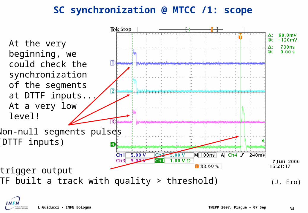
SC synchronization @ MTCC /1: scope
At the very beginning, we could check the synchronization of the segments at DTTF inputs... At a very low level!
Non-null segments pulses(DTTF inputs)
BS trigger output(DTTF built a track with quality > threshold) (J. Ero)

TWEPP 2007, Prague - 07 SepL.Guiducci - INFN Bologna 35
SC synchronization @ MTCC /2: spy data plots
MB1
MB2
MB3
WH+2 Sect10WH+1 Sect10 WH+2 Sect11
MB3theta
Plots from SC SPY
theta hitsoutputted
7 BXs beforephi segments
MB3 timing is
downgraded by a
“special” configuration
Timing was found to be stable across several days of running
TWEPP 2007, Prague - 07 SepL.Guiducci - INFN Bologna 36
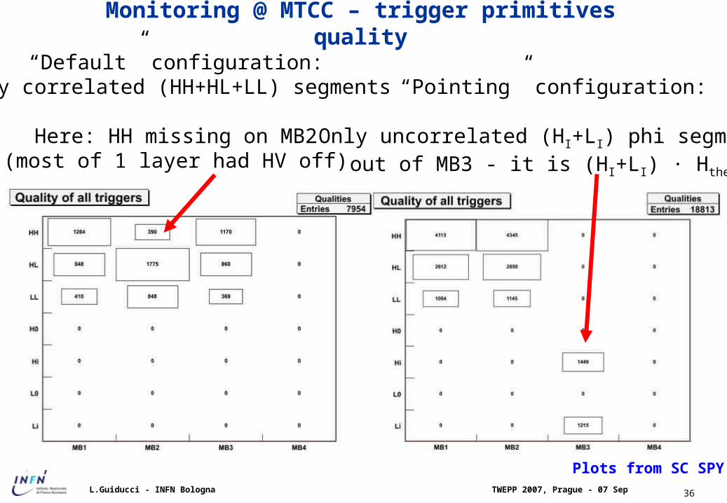
Monitoring @ MTCC – trigger primitives quality
“Default” configuration:Only correlated (HH+HL+LL) segments
Here: HH missing on MB2(most of 1 layer had HV off)
“Pointing” configuration:
Only uncorrelated (HI+LI) phi segments out of MB3 - it is (HI+LI) · Htheta
Plots from SC SPY

TWEPP 2007, Prague - 07 SepL.Guiducci - INFN Bologna 37
DQM trigger plots @ commissioning – chamber detail
1 2
3 4
1 Track segment quality vs BX
2 First and second track segment qualities
3 First and second track segment BX
4 Theta hits BX

TWEPP 2007, Prague - 07 SepL.Guiducci - INFN Bologna 38
Eye pattern at 1.6 Gb/s
625 ps

TWEPP 2007, Prague - 07 SepL.Guiducci - INFN Bologna 39
Trigger system overview
• On-line reduction from interaction rate (~700 MHz) to storage rate (~ 100 Hz)
Trigger chain based on 2 levels
• Level-1 custom processors muon and calorimeters pipelined (sync. 40 MHz) no dead-time 3.2 μs overall latency
• High level Software on CPU farm ~ s latency
Level-1 Accept?
Storage

TWEPP 2007, Prague - 07 SepL.Guiducci - INFN Bologna 40
Level-1 Muon Trigger overview
On-detector electronics
Counting room electronics
Underground Counting Room

TWEPP 2007, Prague - 07 SepL.Guiducci - INFN Bologna 41
Meantimer

TWEPP 2007, Prague - 07 SepL.Guiducci - INFN Bologna 42
Design Method

TWEPP 2007, Prague - 07 SepL.Guiducci - INFN Bologna 43
Sector Collector Block Scheme

TWEPP 2007, Prague - 07 SepL.Guiducci - INFN Bologna 44
ER = - ln(1-CL)/N
Cable transmission tests BER < 2 10-12
Prototype boards tests BER < 2 10-9
Production boards tests BER < 2 10-6
Binomial distribution, with large N (number of patterns) and no errors detected:
Bit error rates from tests