1 voltmeter circuit –extremely high resistance –always connected across or in parallel with the...
TRANSCRIPT

1
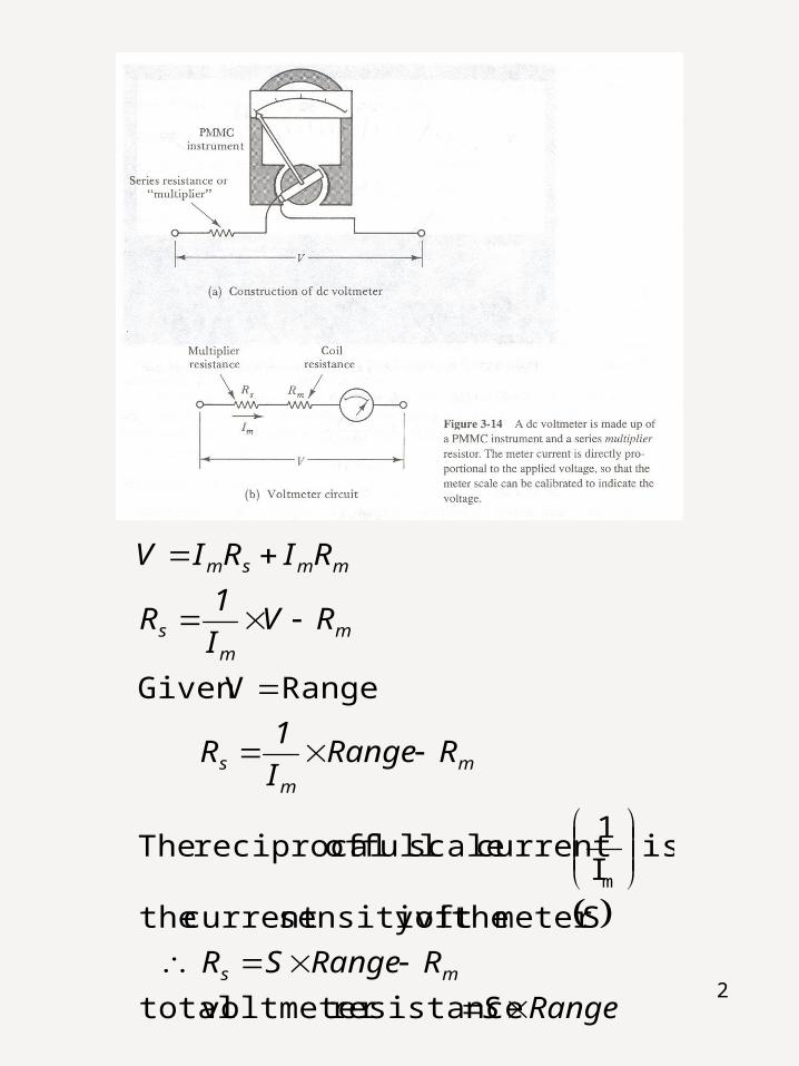
Voltmeter Circuit– Extremely high resistance
– Always connected across or in parallel with the points in a circuit at which the voltage is to be measured
– The voltmeter range is increased by connecting a multiplier resistance with the instrument (single or individual type of extension of range).
Chapter 5: DC Voltmeter
2
RangeS
RRangeSR
RRangeI
1R
RVI
1R
RIRIV
ms
mm
s
mm
s
mmsm
resistancevoltmetertotal
Smetertheofysensitivitcurrentthe
isI
1currentscalefullofreciprocalThe
RangeVGiven
m

3
Example 5.1: A PMMC instrument with FSD of 100 A and a coil resistance of 1k is to be converted into a voltmeter. Determine the required multiplier resistance if the voltmeter is to measure 50V at full scale (Figure 3-15). Also calculate the applied voltage when the instrument indicate 0.8, 0.5, and 0.2 of FSD.
Solution
For V=50V FSD
mm
s RI
VR
kΩ499kΩ1μA100
V50R
μA100I
s
m

4
At 0.8 FSD:
At 0.5 FSD:
At 0.2 FSD:
• The voltmeter designed in Example 5.1 has a total resistance of Rv = Rs+Rm = 500k . Since the instrument measures 50V at full scale, its resistance per volt or sensitivity is 500k / 50V =10 k / V.
• The sensitivity of a voltmeter is always specified by the manufacturer, and it is frequently printed on the scale of the instrument.
V40kΩ1kΩ499μA80
RRIV
μA80μA1000.8I
msm
m
V25kΩ1kΩ499μA50V
μA50I m
V10kΩ1kΩ499μA20V
μA20I m

5
– Swamping Resistance• The change in coil resistance (Rm)
with temperature change can introduce errors in a PMMC voltmeter.

6
• The presence of the voltmeter multiplier resistance (Rs) tends to swamp coil resistance changes, except for low voltage ranges where Rx is not very much larger than Rm.
– Multi-range Voltmeter• In Figure 3.16(a), only one of the
three multiplier resistors is connected in series with the meter at any time.
• The range of this voltmeter is
V = Im(Rm+R)
where R can be R1, R2, or R3

7
• In Figure 3.16(b), the multiplier resistors are connected in series, and each junction is connected to one of the switch terminals.
• The range of this voltmeter can also be calculated from the equation
V = Im(Rm+R)
where R can now be R1, R1+R2, or R1+R2 +R3.
• Of the two circuits, the on in Figure 3.16(b) is the least expensive to construct. This is because all of the multiplier resistors in Figure 3.16(a) must be special (nonstandard) values, while in Figure 3.16(b) only R1 is a special resistor.

8
Example 5.2: A PMMC instrument with FSD = 50A and Rm = 1700 is to be employed as a voltmeter with ranges of 10V, 50V, and 100V. Calculate the required values of multiplier resistors for the circuits of Figure 3.16(a) and (b).
Solution
kΩ198.3
Ω1700μA50
V10
RI
VR
I
VRR
a163FigureinasCircuit
mm
1
m1m
M.
A
VR
k.
A
VR
99831
170050
100
3998
170050
50
3
2

9
kΩ800
Ω1700kΩ198.3μA50
V50
RRI
VR
I
VRRR
kΩ198.3
Ω1700μA50
V10
RI
VR
I
VRR
b163FigureinasCircuit
m1m
22
m
221m
mm
11
m
11m

10
– Voltmeter Internal Resistance: Rin
RangeS
VI
1RRR
RRIRIV
mmsin
msminm
MΩ1
Ω1700kΩ198.3kΩ800μA50
V100
RRRI
VR
I
VRRRR
m12m
33
m
3321m

11
Example 5.3: From Example 5.2, Calculate Rin for each range
Solution
Find sensitivity
Range V1 = 10V
Range V2 = 50V
Range V3 = 100V
V
kΩ20
μA50
1
I
1S
FSD
kΩ200V10V
kΩ20R in
MΩ1V50V
kΩ20R in
MΩ2V100V
kΩ20R in

12
– Voltmeter Loading Effect
R th
Vthdc circuit with source
and resistors Vwom
R th
Vthdc circuit with source
and resistorsVwmVwmV V
Vwom

13
100%V
VV
100%X
XXAcc%1Error%
100%RR
RAcc%
100%V
VAcc%
RR
R
V
VAccuracy
RRR
VV
VV
wom
wmwom
t
mt
Thin
in
wom
wm
Thin
in
wom
wm
inThin
Thwm
Thwom

14
Example 5.4 A voltmeter with sensitivity of 20kΩ/V is used for measuring a voltage across R2 with range of 50V as shown in figure below. Calculate
a) reading voltage
b) accuracy of measurement
c) error of measurement
Solution
inThTh RRV ,,Find
kkkRRR
kkk
V
RRR
EVV
Th
womTh
100200//200//
50200200200
100
21
221

15
MVV
kRangeSRin 150
20
wmVvoltage,readingFind
VVkM
M
VRR
RV wom
Thin
inwm
45.45501001
1
VMkM
V
RRR
VV in
Thin
Thwm
45.4511001
50
or
tmeasuremenofaccuracyFind
909.050
45.45V
VV
VAccuracy
wom
wm
909.02001
1
or
kMM
RR
RAccuracy
Thin
in

16
tmeasuremenoferrorFind
091.050
45.4550or
091.0909.011
VVV
X
XXError
AccError
t
mt