1 wireless and mobile all-ip networks yi-bing lin [email protected]
Post on 21-Dec-2015
220 views
TRANSCRIPT
2
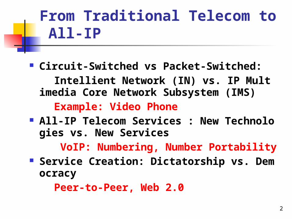
From Traditional Telecom to All-IP
Circuit-Switched vs Packet-Switched:
Intellient Network (IN) vs. IP Multimedia Core Network Subsystem (IMS)
Example: Video Phone All-IP Telecom Services : New Technologies vs.
New Services
VoIP: Numbering, Number Portability Service Creation: Dictatorship vs. Democracy
Peer-to-Peer, Web 2.0

3
All-IP Architecture

4
Issues on Mobile All-IP Network
Short Message Service (SMS) and IP Network Integration
SMS is considered as the application level signaling mechanism.
Mobility Management
GSM: Location Area (LA) tracking
GPRS: Routing Area (RA), cell tracking
UMTS: RA, UTRAN RA (URA), cell tracking Session Management
PDP context is introduced.

5
Issues on Mobile All-IP Network Mobile Core Networks that Support All-IP:
UMTS: GPRS
cdma2000: PDSN (Packet Data Support Node) UMTS Charging Protocol On-line Charging System (OCS) Mobile All-IP Network Signaling Traditional: SS7 is supported by MTP (Message Transfer Part) All-IP: SS7 is supported by SCTP (Stream Control Transport Protocol)
6
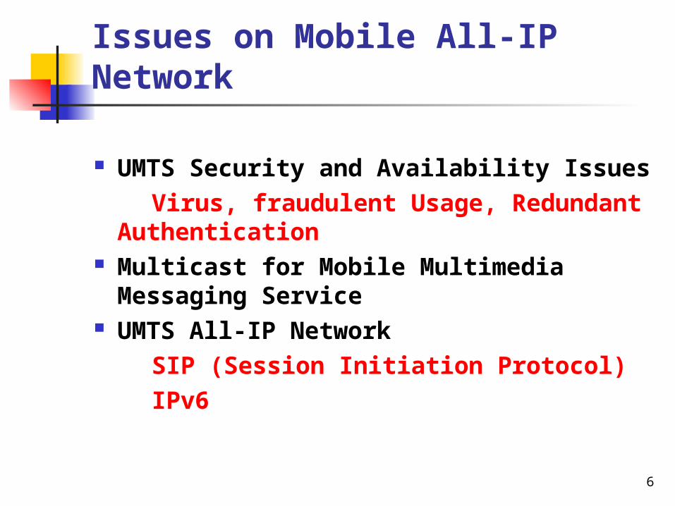
Issues on Mobile All-IP Network
UMTS Security and Availability Issues
Virus, fraudulent Usage, Redundant Authentication
Multicast for Mobile Multimedia Messaging Service
UMTS All-IP Network
SIP (Session Initiation Protocol)
IPv6

7
Identities in UMTS
Why is identity management important?
Billing, Security, Service
ANSI 41: MDN = MIN
GSM MAP: MDN ≠ MIN How are identities assigned in UMTS PS
service domain?
Service: APN
MS: IP address

8
Access Point Name (APN)
An APN is used in UMTS/GPRS as a reference point to external PDN that supports the services to be accessed by an MS.
The APN information is permanently distributed and maintained in the HLR, the GGSN and the Domain Name Server (DNS).

9
APN Allocation A set of APN labels is defined in the HLR. Each mobile user can subscribe to one or more APNs from
this set. The labels of these subscribed APNs are then stored in the
MS at the subscription time. Among the subscribed APNs, there is one default APN. If a user attempts to access a service without specifying the
APN, then the default APN is used. Additionally, the HLR may also define a wild card APN ``
*", which allows an MS to access any unsubscribed APNs. For each APN, the DNS keeps an IP address list of the GG
SNs associated with this APN label.

10
APN Configurations
UTRAN
(3) ISP
GGSN
RADIUSserver
DHCPserver
FW
NAT
(1) INTERNET
(2) WAP
(4) COMPANY
RADIUSserver
RADIUSserver
DHCPserver
SignalingSignaling and data
DHCP: Dynamic Host Configuration ProtocolFW: FirewallGGSN: Gateway GPRS Support NodeMS: Mobile Station
NAT: Network Address translatorRADIUS: Remote Authentication Dial-In User ServiceUMTS: Universal Mobile Telecommunication ServiceUTRAN: UMTS Terrestrial Radio Access Network
(5)
(6)
(7)
(8)
(9) (10)
SGSN
DNS
HLR
(11)
(12) (13)

11
IP Address Allocation: Access Modes
Based on the APN setting specified in 3GPP TS 29.060, the GGSN provides two access modes for IP address allocation to an MS
Transparent Non-transparent

12
Transparent Access Mode
In the transparent access mode, the mobile operator acts as an Internet service provider, and an MS is given an IP address from the operator's IP address space.
The IP address can be allocated statically at the subscription time or dynamically at the activation of the PDP context.
The transparent access mode is exercised if the requested APN INTERNET.

13
Non-transparent Access Mode
In the non-transparent access mode, the mobile operator only provides a user the access channel to an Internet service provider (if the APN is ISP) or a company (if the APN is COMPANY).
The IP address pool is owned by the Internet service provider or the corporate, and the IP address for an MS is dynamically allocated.

14
IP Address Allocation (I)
The IP addresses can be allocated by either the GGSN, a Dynamic Host Configuration Protocol (DHCP) server, or a Remote Authentication Dial-In User Service (RADIUS) server.
In the transparent access mode, the GGSN may allocate the IP address for a user by using its own address pool.
In the current implementation, IPv6 addresses can only be allocated by this alternative.
15
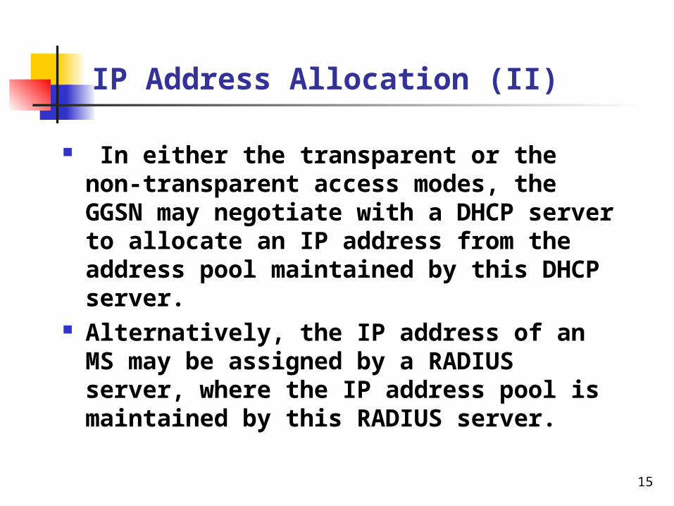
IP Address Allocation (II)
In either the transparent or the non-transparent access modes, the GGSN may negotiate with a DHCP server to allocate an IP address from the address pool maintained by this DHCP server.
Alternatively, the IP address of an MS may be assigned by a RADIUS server, where the IP address pool is maintained by this RADIUS server.

16
IP Address Allocation (III)
APN label INTERNET WAP ISP COMPANY
GGSN
access mode
Transparent Transparent Non-
transparent
Non-
transparent
IP address allocator
GGSN/ DHCP server
GGSN/ DHCP server
DHCP server
RADIUS
RADIUS
IP address type
IPv6/IPv4 IPv4 IPv4 IPv4

17
PDP Context
Before an MS can access any mobile data service, the Packet Data Protocol (PDP) context for the service must be activated.
The PDP context specifies the application-layer packet data protocol and the routing information used for the communication session.
The PDP context is maintained in the MS, the SGSN, and the GGSN.

18
During the PDP context activation procedure , the MS specifies a requested APN.
Then the SGSN uses this requested APN to select a GGSN.
If the user does not specify any requested APN in the activation procedure, the default APN is chosen by the SGSN.
PDP Context Activation

19
MS UTRAN SGSN GGSN
1. Activate PDP Context Request
DNS
The MS specifies the APN in the Activate PDP Context Request message and sends it to the SGSN.
PDP Context Activation: Step 1

20
MS UTRAN SGSN GGSN
1. Activate PDP Context Request
2. Radio Access Bearer Assignment Procedure
DNS
The SGSN negotiates with the UTRAN to allocate the radio bearer bandwidth for the data session.
PDP Context Activation: Step 2

21
MS UTRAN SGSN GGSN
1. Activate PDP Context Request
2. Radio Access Bearer Assignment Procedure
3. APN Query and response
DNS
The SGSN checks if the requested APN (obtained from the Activate PDP Context Request message sent by the MS) is specified in the APN list of the subscription data for the MS. If not, the default APN is used. Then the SGSN creates the PDP context for the user, and sends the requested APN to the DNS server. The DNS server uses this APN to derive the GGSN's IP address.
PDP Context Activation: Step 3

22
MS UTRAN SGSN GGSN
1. Activate PDP Context Request
2. Radio Access Bearer Assignment Procedure
3. APN Query and response
4. Create PDP Context Request
DNS
Based on the GGSN's IP address obtained from the DNS, the SGSN sends the Create PDP Context Request message to the GGSN to establish a GTP tunnel between the SGSN and the GGSN, which will be used as the packet routing path between the GGSN and the MS.
PDP Context Activation: Step 4

23
MS UTRAN SGSN GGSN
1. Activate PDP Context Request
2. Radio Access Bearer Assignment Procedure
3. APN Query and response
4. Create PDP Context Request
DNS
5. Create PDP Context Response
Step 5. The GGSN creates a PDP context for the MS. This PDP context records the requested APN, PDP type, MSISDN, and IP address. The GGSN allocates an IP address for the MS by using either transparent or non-transparent access mode, and determines the tunneling mechanism to the destination external PDN.

24
MS UTRAN SGSN GGSN
1. Activate PDP Context Request
2. Radio Access Bearer Assignment Procedure
3. APN Query and response
4. Create PDP Context Request
DNS
5. Create PDP Context Response
6. Activate PDP Context Accept
Step 6. Finally, the SGSN informs the MS that the session setup is completed

25
All-IP Telecom. Trial in Taiwan
Under the M-Taiwan Program, FarEasTone is developing IMS Service Platform.
APTG is conducting VoIP Service Trial.
Keelung City
NANKANGSOFTWAREPARK
Nantou County
Taichung County
Hsinchu County
Taoyuan County
Miaoli County
Matsuh County
NATIONALMUSEUM OFHISTORY
TAIPAIVOIPCenter
Taichung City
Taitung County
Yunlin County
Penghu County
TainanCity
Chiayi County
Hualien County
Chiayi City
TainanCounty

26
Call Setup in APTG Trial
PSTN
APTG IP backbone
(4) Taipei switch
(5) Softswitch
(MGCF/MGW)
Originating switch
IP-PBX (1) AP
(2) Proxy server (CSCF)
(3) Caller

27
Performance Measurement
Mean Opinion Score (MOS)

28
Conclusions
The SIP protocol does not provide all features needed to implement existing telecommunications services. For example, the flash-hook signal for the call waiting service is implemented proprietarily in the APTG trial.
There are too many kinds of IP CPEs. Some of them may not be compatible with the networks, and may show very poor performance. Furthermore, some CPEs may be complicate to operate, and cannot be simply “plug-and-play”.
Although the cost for deploying All-IP VoIP network is lower than traditional PSTN network, it is not clear if the same advantages are guaranteed for maintenance and operations of the VoIP network.

29
Appendix A: IPv4 vs IPv6
The above procedure assumes IPv4 IP address allocation. For IPv6, the IP address allocation is different.
Support of public IP address is a major difference for UMTS address allocation between IPv4 and IPv6.
For IPv4, the MS is typically allocated a private address because of limited IPv4 address space.
For IPv6, the MS is always allocated a public address.

30
IPv6 Address Allocation
At Step 5 of the PDP context activation procedure, the GGSN allocates a complete IP address for IPv4.
For IPv6, there are two alternatives for dynamic address allocation: stateless address allocation and stateful address allocation.
Like IPv4, the stateful IPv6 address is allocated by DHCP server at Step 5.
On the other hand, in stateless address auto-configuration, the GGSN allocates a part of the IPv6 address called link-local address for the MS by using its own IPv6 address pool at Step 5.
Then the MS generates the public IP address by combining the link-local address and a network-prefix address.

31
MS UTRAN SGSN
1. PDP Context Activation Procedure
2. Router Solicitation
3. Router Advertisement
GGSN
4. GGSN-Initiated PDP Context Modification Procedure
IPv6 Stateless Auto-configuration Procedure

32
Stateless Address Auto-configuration (I)
Step 1: the MS first obtains the link-local address in the PDP context activation procedure.
Step 2: the MS activates the IPv6 address auto-configuration by sending the Router Solicitation message to the GGSN.
Step 3: The GGSN replies with the Router Advertisement message, which includes the network-prefix address.
After the MS has received the Router Advertisement message, it obtains the IPv6 address by concatenating the link-local address and the network-prefix address.
Step 4: Then the GGSN updates the IPv6 address of the PDP contexts in the SGSN and the MS.

33
Stateless Address Auto-configuration (II)
To avoid conflict of link-local address assignment, the GGSN shall exercise neighbor discovery with other GGSNs.
Note that in traditional IPv6 stateless address allocation, neighbor discovering is conducted by the mobile host. In UMTS, neighbor discovery is exercised by the GGSNs.
Also note that existing UMTS core network is developed based on the IPv4 transport network.
Therefore, IPv6 packets are carried on top of the IPv4-based GTP tunnel, which are invisible to the UMTS core network.

34
UMTS and External PDN Interworking
The GGSN interworks the external data network through the Gi interface. The interworking mechanisms may be different for various APN configurations.
For the INTERNET and WAP APNs, the GGSN connects to the external PDN directly through Ethernet or leased lines.
For the ISP APN, the external PDN can be connected to the GGSN either through the leased lines or the VPN. If the Internet service provider connects to the GGSN through VPN, then tunneling is required.
For the COMPANY APN, tunneling is always required for interworking between the GGSN and the corporate intranet.

35
Tunneling Methods
Three tunneling methods have been proposed for UMTS.
IP-in-IP tunneling. Generic Routing Encapsulation (GRE) tunneling Layer 2 Tunneling Protocol (L2TP) tunneling

36
IP-in-IP Tunneling
InternetMS GGSN
(1) IP
(2) IP
Application
VPNGateway
ApplicationServer
Intranet ofa corporate

37
Intranet ofa corporate
InternetMS GGSN
(1) IP
(2) GRE
(3) PPP
Application
VPNGateway
ApplicationServer

38
Intranet ofa corporate
InternetMS GGSN
(1) IP
(2) UDP
(3) L2TP
(4) PPP
Application
VPNGateway
ApplicationServer
(5) IP

39
Tunneling method
Overhead Multiprotocol support
Transport support
MS support
IP-in-IP low no IP IP
GRE(PPTP) medium yes IP PPP
L2TP high yes IP/UDP, FR, ATM
IP

40
Each of the above three methods can be used together with IPsec to provide protection for packet delivery.
If an MS supports both PPP and IP, then all these three tunneling methods can be used to provide data sessions to this MS.

41
Quality of Service
UMTS defines four QoS classes for user data traffic: conversational, streaming, interactive, background
The conversational and the streaming classes support real-time traffic for services such as voice and streaming video.
The interactive and the background classes support non real-time traffic for services such as web browsing and email.
Each class defines parameters including maximum bit rate, guaranteed bit rate, bit error ratio, transfer delay, etc.

42
QoS: VoIP and Internet Access
QoS parameter
VoIP (conversational)
Internet access (Interactive )
Maximum bit rate
16 Kbps 128 Kbps
Guaranteed bit rate
12.2 Kbps 100 Kbps
Bit error ratio
104 10-6
Transfer delay
100 ms unguaranteed

43
End-to-end IP QoS Models (I)
Scenario 1 2 3 4 5
MS -- DS DS RSVP
RSVP SBLP
GGSN DS DS DS DS RSVP
DS SBLP
External PDN
DS DS DS DS RSVP
DS
Remote host
DS DS DS RSVP
DS RSVP
DS SBLP
RSVP: Resource Reservation ProtocolSBLP: Service-Based Local Policy

44
End-to-end IP QoS Models (II)
The end-to-end QoS for packet switched service is negotiated among the MS, the GGSN and the remote host located in the external PDN.
3GPP TS 23.207 assumes that the external PDN supports Diffserv QoS mechanism, and the GGSN is required to perform the Diffserv edge function in all scenarios.
Within the UMTS network (MS-UTRAN-SGSN-GGSN), the IP QoS is translated and maintained by the UMTS QoS mechanism where the QoS parameters are set in the PDP contexts.

45
GGSN QoS Architecture
SGSN
incoming GTP packets
outgoing GTP packets
GGSNOutgoing IP packets
Resource Manager
AdmissionController
PacketScheduler
Packet Mapper
TrafficConditioner
PacketClassifier External
Data Network
Incoming IPpackets
1
2
3
4
5
6
Step 1
Step 2
Step 3
Step 4
Step 5Step 6
Step 7
Step 8
Step 9
GTP/IP PacketConverter
7
QoS Control Signaling
User data

46
UMTS QoS vs DSCP
UMTS QoS class
DSCP codepoint Delivery Priority
Conversational Expedited Forward 1 (high)
Streaming Assured Forward class 1
2
Interactive Assured Forward class 2
3
Background Best Forward 4 (low)

47
Remarks on GGSN QoS
The Resource Manager and the Admission Controller are involved in PDP context activation.
The Packet Classifier, Traffic Conditioner, Packet Mapper and Packet Scheduler are involved in packet delivery.
48
Appendix B: Multicast for Mobile Multimedia Messaging Service
Short Message Service (SMS) allows mobile subscribers to send and receive simple text message in 2G systems (e.g. GSM).
Multimedia Message Service (MMS) is introduced to deliver messages of sizes ranging from 30K bytes to 100K bytes in 2.5G systems (e.g. GPRS) and 3G systems (e.g. UMTS)
The content of an MMS can be text (just like SMS), graphics (e.g., graphs, tables, charts, diagrams, maps, sketches, plans and layouts), audio samples (e.g., MP3 files), images (e.g., photos), video (e.g., 30-second video clips), and so on.

49
MMS Architecture [1/2]

50
MMS Architecture [2/2]
The MMS user agent (a) resides in a Mobile Station (MS) or an external device connected to the MS, which has an application layer function to receive the MMS.
The MMS can be provided by the MMS value added service applications (b) connected to the mobile networks or by the external servers (d) (e.g., email server, fax server) in the IP network.
The MMS server (c) stores and processes incoming and outgoing multimedia messages.
The MMS relay (e) transfers messages between different messaging systems, and adapts messages to the capabilities of the receiving devices. It also generates charging data for the billing purpose. The MMS server and the relay can be separated or combined.
The MMS user database (f) contains user subscriber data and configuration information.
The mobile network (g) can be a WAP (Wireless Application Protocol) based 2G, 2.5G or 3G system. Connectivity between different mobile networks is provided by the Internet protocol.

51
Short Message Multicast Architecture
VLR1 1
VLR2 2
VLR3 0
MCH (HLR)
LA1 0
LA2 1
MCV (VLR1)
LA3 0
LA4 2
MCV (VLR2)
LA5 0
LA6 0
MCV (VLR3)

52
Appendix C: Short Message Service and IP Network Integration
BTS
BTS
BSC IWMSC
SM-SC
SMSGMSC
BTS
BTS BSC MSC
(1) (2)
(3)
(4)
(5)(6)
GSM SMS Network Architecture

53
SMS-IP Integration: SM-SC-based
Mobile Network
Mobile Network
SM-SC Gateway
IP Network
IP Network
In most commercial implementations, SMS and IP networks are integrated through SM-SC.

54
NCTU-SMS

55
iSMS

56
Simple Tone Language (STL)
The regular expressions are used for the STL grammar. In STL, a music tone is defined as
tone = [style] [tempo] [volume] [repeat] (note-expression)+
where style is of the format
style = “S” “0” (“0” | “1” | “2”) S00: Natural Style (rest between notes)
S01: Continuous Style (no rest between notes)
S02: Staccato Style (shorter notes and longer rest period)

57
STL Representation for a Taiwanese Song
Notes: STL: t13 3e 3f 5 3e 3f 5 3e 5f 5e 6f 5 5e 6f 5e 3f 3
2z 3f 1c 2z 3f 1c

58
Appendix C: GGSN Functionalities
The GGSN plays the role as a gateway, which controls user data sessions and transfers the data packets between the UMTS network and the external PDN.
The meta functions implemented in the GGSN are described as follows:
Network access control Packet routing and transfer Mobility management

59
Functions of UMTS Network Elements