10-3. camera station general€¦ · 10-3.__ camera station . general . ... verify video signal...
TRANSCRIPT

10-3.__ CAMERA STATION
GENERAL The Contractor shall furnish and install the following closed circuit television (CCTV)
equipment at each camera station as described in these special provisions and as shown on the plans:
1. One integrated camera unit. 2. One CCTV pole and camera mounting adapter 3. One camera control unit (CCU). 4. One video encoder unit (VEU). 5. Power strip. 6. Hybrid camera cable (HCC), connectors and fittings as required. 7. Interface cable and conductors as required. 8. Equipment shelf with brackets as required. INSTALLATION OF CAMERA STATION The Contractor shall install CCTV pole with foundation, conduits and pull boxes as required
and as shown on the plans. The type of CCTV pole is shown on the plan and shall meet the specifications describe elsewhere in these special provisions. The Contractor shall install and terminate the HCC with connectors as shown on the plans. The HCC shall connect to camera pigtail cable and secure to the pole as shown on the plans for strain-relief.
The integrated camera unit shall be installed on camera mounting plate as shown on the plans. The integrated camera unit shall be secured to the mounting plate using the stainless steel bolts provided with the integrated camera unit. Before each bolt is fastened, a locking type coating shall be applied to the threads. The coating shall lock the bolt and nut in place, making it impossible to turn the bolt or nut without tools. This coating shall last through and be effective through at least ten insertions and withdrawals of the bolt or nut.
The Contractor shall install CCU, VEU, router, power strip, 8-position connecting block, equipment shelves and all the interface cables in the controller cabinet as shown on the plans. The power strip shall be mounted on the rear mounting rack of the controller cabinet.
The Contractor shall furnish all materials necessary to provide a complete and functional camera station in accordance with these special provisions. Miscellaneous equipment, and materials not mentioned but necessary to provide a complete and fully operational camera station shall be furnished by the Contractor as incidental to the work for which no additional compensation will be allowed therefore.
All items furnished under this contract shall be new and shall be the latest version. CAMERA STATION TESTING Prior to removal or relocation of existing CCTV equipment including cables, pole, camera,
pan and tilt unit, controller cabinet, etc., the Engineer in the presence of the Contractor will test the camera station in the field. Existing equipment that fail during this test period will be replaced or repaired by the State or, if directed by the Engineer, by the Contractor, and such work will be paid for as extra work as provided in Section 4-1.03D of the Standard Specifications. The Contractor shall notify the Engineer in writing fifteen days prior to the scheduled testing.

Upon completion of work, each camera station shall be subjected to post-installation tests as outlined herein. All software shall be provided and loaded before the start of testing The District Electrical Systems Branch personnel, arranged by the Engineer and in the presence of the Contractor, shall perform all tests. The Contractor shall notify the Engineer in writing fifteen days prior to the scheduled testing. Upon receipt of the notification, the Engineer shall contact Office of Electrical Systems at (510) 286-6142. The Contractor shall provide all necessary equipment required to access the CCTV equipment for testing.
The testing shall consist of five consecutive days of continuous satisfactory operation of each camera station. If any material and equipment furnished and installed by the Contractor in this project is found defective or otherwise unsuitable, or the workmanship does not conform to the accepted standards, the Contractor shall replace such defective material and equipment at no cost to the State.
The Contractor may offer rejected material or equipment for consideration provided all non-compliance has been corrected and pretested by the Contractor. After all defects have been corrected, the camera station shall be re-tested until five consecutive days of continuous satisfactory operation is obtained.
The post-installation tests shall consist of, but not be limited to, inspection and functional testing in accordance with these special provisions.
Inspection shall consist of, but not be limited to, verification of correct wiring terminations, correct cable interconnections, good workmanship and compliance with these special provisions.
Functional testing shall include, but not be limited to, the following: a. Verify all local mode CCTV operations using the CCU front panel controls. b. Verify video signal output from CCU with a National Television Systems Committee
(NTSC) monitor. c. Verify the correct operation of the auto/manual iris and focus, and manual zoom
functions. d. Verify the correct operation of the pan/tilt function. The pan/tilt function shall be tested
over 355 degrees in the horizontal plane and +20 to -90 degrees in the vertical plane e. Verify the correct operation of the preset positions.
10-3.__ INTEGRATED CAMERA UNIT
GENERAL Each integrated camera unit shall consist of a camera, lens, receiver/driver, pan/tilt assembly,
environmental housing, sunshield and pigtail cable with connector. The integrated camera unit shall automatically switch to monochrome mode when ambient light level is at 20 foot-candles and switch back to color at 180 foot-candles.
Each integrated camera unit shall be assembled, inspected and tested in accordance with these special provisions prior to delivery to the job site. Installation, operations and maintenance manuals shall also be submitted at the time of delivery. The Contractor shall submit the applicable documents of the U.S. Military Specification (MIL-SPEC), Underwriters Laboratories Inc. (UL), Electronics Industries Association (EIA) Standards and other Standards from parts of the specification to the extent specified in these standards. In the event of a conflict between the content of this section and the content of the specification, the standards defined in this section shall supersede.

Military Specification Documents MIL-I-45208A Inspection System Requirements, Dec. 16, 1963 MIL-C-45662 Calibration System Requirements, June 10, 1980 MIL-STD-416A Electromagnetic Interface Characteristics Requirements for Equipment, Subsystems
& Systems, Aug. 1, 1968 MIL-E-5400T Electronic Equipment, Airborne General Specification MIL-STD-810 Environmental Test Methods, 19 July 1983 MIL-C-5541 Chemical Conversion Coatings on Aluminum Alloys, June 3, 1970
Underwriters' Laboratory, Inc. and other documents
UL-796 Printed Circuit Boards EIA-170A Electrical Performance Standards Color Television Studio Facilities EIA RS-330 Electrical Performance Standards for Closed Circuit Television (CCTV) Camera 525/60
Interlaced CAMERA Each camera shall meet the following specifications at a minimum:
Imager Interline transfer Progressive Scan CCD with mosaic-type color compensating filter Image Area 1/4" Format, 3.6 mm (H) x 2.7 mm (V) Resolution 540 horizontal; 350 vertical Picture Elements 811 (H) x 508 (V), Total 411,988 Video Output NTSC, 1 V p-p @ 75 ohms, unbalanced Lens Aperture: f/1.4 (wide angle) to f/4.2 (telephoto) Optical Zoom Range 35X, 3.4 mm to 119 mm Digital Zoom Range 1X (Off) through 210X, Smooth transition from Optical to Digital Zoom Horizontal Angle of View
Optical: 55.8° to 1.7°; At 10X Digital: 55.8° to 0.17°.
Focus Distance. 40" in telephoto, 0.4" in wide angle Digital Compass 8 or 16 direction point compass annotation with primary direction spelled out and
intermediate directions abbreviated with two letters Auto Focus Selectable Auto/Manual Manual Focus Speed Approximately 2.0 seconds to full range Minimum Scene Illumination
For Reliable Auto Focus, 30 percent video
Zoom & Focus Presets
64 preset positions with auto focus and ID
Flash Memory Update firmware and new features via serial communication Shutter speeds 1/60; 1/120; 1/180; 1/250; 1/500; 1/1,000; 1/2,000; 1/4,000; 1/10,000; 1/30,000 second Auto Iris Automatically adjusts to compensate for changes in scene illumination to maintain
constant video level output within sensitivity specifications Manual Iris Changing the video level to give the effect of open iris/close iris Gamma 0.45 AGC 0 to 28 dB Color Balance Auto Tracking Color Balance/Manual with adjustable Red and Blue Levels Signal to Noise Ratio >50 dB Synchronization Crystal or Phase-Adjust Line Lock on 60 Hz Sensitivity @F1.4, Wide Angle 35 IRE
0.5-Lux @ 1/60 s, F1.4, Shutter, Color I.R. Cut On 0.05-Lux @ 1/2 s, F1.4, Shutter, Color I.R.Cut On 0.2-Lux@ 1/60 s, F1.4, Shutter, monochrome mode I.R. Cut Off 0.01-Lux@ 1/4 s, F1.4, Shutter, monochrome mode I.R. Cut Off

Pan & tilt function specifications:
1 Continuous rotation capability in either direction 2 110° of tilt movement, +20° to –90° unobstructed 3 Pan Speed (Operator Control): Variable from 0.1°/s to 80 °/s 4 Pan Speed (Preset Control): >140°/s 5 Tilt Speed (Operator Control): Variable from 0.1°/s to 40 °/s 6 Tilt Speed (Preset Control): 140°/s 7 64 Pan & Tilt preset positions with repeatability within ±0.5° 8 The positioning system shall be invertible if inverse mounting is required
The integrated camera unit shall have eight programmable camera movement sequences.
Each sequence is programmed by selecting the preset position by number, and then selecting a dwell time. The presets can be used in any order, and the same preset may be used more than once as long as the total number of preset positions used does not exceed 32. The dwell time defines the length of time paused at each preset position. It can be from 1 second to 60 seconds. The dwell time can be changed individually for all stops on the sequence. If the appropriate preset ID is programmed, it shall be displayed for each preset position used on the sequence. The sequence shall stop upon receipt of a pan command. All programmable functions shall be stored in non-volatile memory.
The camera housing shall be a corrosion resistant and tamper proof sealed and pressurized
housing with five pounds dry nitrogen with Schrader purge fitting and 20 psi relief valve for each camera. The size of the housing shall be 3 1/2" diameter or smaller. The housing exterior shall be finished by pre-treatment with conversion coating and baked enamel paint. The camera enclosure shall be designed to withstand the effects of sand, dust and hose-directed water.
The internal humidity of the housing shall be less than 10 percent, when sealed and
pressurized. Desiccant packs shall be securely placed inside the housing to absorb any residual moisture and maintain internal humidity at 10 percent or less. The housing shall include a thermostatically controlled heating pad rated at 115 V(ac) 100 W maximum.
A sun shield or visor shall be provided to shield the lens from direct sunlight. The integrated camera unit shall include a character generator. The text characters shall be
uppercase white with black border impose on the video stream. A maximum of six lines of user programmable alphanumeric text shall be displayed through serial communications. Messages can be positioned at either the top or the bottom of display. The Right side positioning is accomplished by padding left side of message with spaces. Blank lines shall not be displayed. Any programmed line being displayed shall fill in toward the top if top positioning is selected, or toward the bottom if bottom position is selected.
Camera ID shall be used for upper 2 lines with each up to 24 characters long. If both lines are programmed, line 1 of Camera ID shall always appear above line 2 of Camera ID regardless of top or bottom selection.
Preset ID shall be 1 line, up to 24 characters long, user programmable for each of the 64 preset positions. When a preset position is recalled the corresponding preset ID shall be displayed. The preset ID shall remain displayed until a pan, tilt, zoom, manual focus, auto focus select, or another preset command is received.
An 8-point or 16-point compass annotation shall be settable for a true north position. Display shall include North, NE, East, SE, South, SW, West and NW. Position shall be able to be

grouped with the site location or separated from site location. Azimuth and elevation position shall be displayed in 0 - 359 degrees and +95 to –95, respectively. All display shall be user selectable for enable/disable, 3-second time out or permanent display. Sector Message of up to 16 sectors in 360° shall be defined with up to 24 characters long.
Low-pressure indicator shall use 1 line with messages displayed in "blinking" or "non-blinking" mode when activated by low internal pressure. Adjustable set points by altitude shall be provided via the serial port to activate low-pressure. Message shall be enabled or disabled. In maintenance mode readings of the internal pressure of the camera housing shall be displayed from 5 down to 1 psi, in 0.1-psi increments.
Internal temperature indicator shall use 1 line with messages displayed in "blinking" or "non-blinking" mode. Message shall be enabled or disabled. In maintenance mode, camera readings of the internal temperature of the camera housing shall be in 1-degree increments.
Video blanked for up to 8 privacy zones shall be provided. One line numeric messages shall be displayed. Message shall be displayed in "blinking" or "non-blinking" mode and be enabled or disabled. Privacy zones shall be programmed through serial communications.
Control and addressing the integrated camera unit shall be done through RS-422 optically isolated serial communications. Additional protocols shall consist of Cohu, American Dynamics, Javelin, Philips/Bosch, Vicon and Pelco-D. The National Transportation Communications for ITS Protocol (NTCIP) 1205 protocol communications protocol shall be included as an option. Refer to NTCIP 1205 protocol for detailed description.
Upon receipt of any given command, the integrated camera unit shall response in not longer than 1.0 second.
All programmable functions including camera last operating position shall be stored in non-volatile memory and shall not be lost if a power failure occurs. Upon power restoration, the camera shall go through a series of self-testing/calibration and return to the same position it left before the power interruption. System configurations such as video privacy zones, preset text and sector I.D. shall be able to be stored in a computer file and a camera personality can be cloned or uploaded into a camera in the event that a camera replacement is necessary.
PHYSICAL AND MECHANICAL REQUIREMENTS Each integrated camera unit shall not weight more than 20 lbs. Its dimensions shall not
exceed 14" in length, 7" in width and 12" in height (Including mounting base.) The integrated camera unit shall be pole mount version. There shall be four equal spaced mounting holes on the mounting base. Each integrated camera unit shall be provided with four stainless steel hex head bolts to secure the integrated camera unit to the camera mounting plate. All fasteners and nuts used in attaching the integrated camera unit to the mounting plate shall be of grade 18-8 stainless steel. A camera-mounting adapter shall be provided as shown on the plans.
POWER REQUIREMENTS The integrated camera unit shall operate between voltage 89 V(ac) to 135 V(ac), 120 V(ac)
nominal voltage and 50 or 60 Hz. (±3.0 Hz). The integrated camera unit shall conform to National Electrical Manufacturers Association (NEMA) standard TS-2 (1998) for traffic control system 2.1.2. The integrated camera unit shall meet the requirements of Section 2.1.6 "transients, power service" of the NEMA standard TS-2 (1998). The line variation and surge performance shall be tested to meet these specifications by an outside agency, other than the camera manufacturer. The tests shall be provided upon request. The power consumption shall

not exceed a total of 200 watts, in which 100 watts for camera, receiver, pan/tilt driver and 100 watts for heater on.
ENVIRONMENTAL REQUIREMENTS The integrated camera unit shall operate in ambient temperature range from -34°C to +74°C,
in relative humidity up to 100 percent. The unit shall operate when exposure to sand, dust, fungus and salt atmosphere per MIL-E-5400T, paragraph 3.2.24.7, 3.2.24.8, 3.2.24.9 and with shock for up to 10 Gs, 11 ms, in any axis under non-operating conditions, per MIL-E-5400T, para 3.2.24.6. The unit shall not be damaged with sine vibration from 5 to 30 Hz, 1/2 G, 3 axis in one hour. .
CAMERA PIGTAIL AND CONNECTOR The camera pigtail cable shall conform to the specifications for "Hybrid Camera Cable" in
these special provisions. The length of the camera pigtail cable shall not be less than 32". The terminating connector shall be equivalent to an Am phenol 206036-3 with back shell 206070-1.
The contact pin assignment of the connector shall be:
Position Function Position Function 1 Video, 75 ohm 9 Not Used 2 Video Ground 10 Not Used 3 Data Ground 11 Not Used 4 Tx- 12 115 V(ac) Line, Hot 5 Tx+ 13 115 V(ac), Neutral 6 Rx+ 14 Not Used 7 Rx- 15 115 V(ac), Ground 8 Not Used 16 Not Used
The Contractor shall furnish a mating connector, Am phenol 206037-1 with back shell
206070-1 and sixteen contact crimping sockets for each integrated camera unit supplied in the contract.
10-3.__ HYBRID CAMERA CABLE AND CON NECTORS
The Hybrid camera cable (HCC) shall consist of one RG-59/U type analog video coaxial
cable, one 6-No. 22 AWG conductor group, one 8-No. 26 AWG conductor group and a two twist pair 4-No. 26 AWG conductor group in a common outer jacket. The hybrid camera cable cross section is shown on the plans.
The Coaxial cable shall conform to:
Electrical Coax Capacitance (picofarads/ft nominal) 17.3 Impedance (ohms-nominal) 75 Velocity of propagation (nominal) 78 percent Nominal Diameter (inch) 0.242 Insulation Rating 300 V
The cable attenuation at 20 °C shall measure at maximum as:

Frequency (MHz) Nominal dB/ 100 ft
1 0.30 10 0.90 50 2.10
The coaxial cable physical measurements:
Component Nominal O.D. (inches) Copper center conductor 0.040 Foam polyethylene dielectric 0.180 Sealed APA tape with 0.06-inch overlap 0.216 Woven aluminum braid 0.241 PVC outer jacket 0.297
(APA = Aluminum polyolefin and aluminum with adhesive) The 6-No. 22 AWG shall be stranded 7 x 30, tinned copper insulated with 0.009" nominal
wall of S-R PVC and a nominal O.D. of 0.048". The 6 conductors shall be color coded as follows:
1. Black 2. Red 3. Green 4. White 5. Blue 6. Yellow The 8-No. 26 AWG shall be stranded 7 x 34, tinned copper insulated with 0.009" nominal
wall of S-R PVC and a nominal O.D. of 0.037". The 8 conductors shall be color coded as follows:
1. Brown 2. Blue 3. Orange 4. Yellow 5. Purple 6. Gray 7. White with Black Stripe 8. Red with Green Stripe The 4-No. 26 AWG in 2 twisted pairs shall be stranded 7 x 34, tinned copper insulated with
0.009" nominal wall of S-R PVC and a nominal O.D. of 0.037". The 4 conductors shall be color coded as follows:
Pair 1 1. Black 2. White Pair 2 3. Red

4. Green The HCC shall also have a 36 AWG tinned copper braid with 90 percent coverage, an O/A
binder of 0.001" polyester 25 percent overlap, and an outer jacket conforming to: color to match Fed-Std-595 color No. 24091, material 0.032" dark gray UV resistant PVC to 0.425" O. D. and must pass the VW-1 vertical flame test. Fillers shall be used as required to form a uniform round cable. The insulation rating of the overall cable jacket shall be 300 V.
The manufacture identification shall be surface printed in white ink every foot along the length of the cable.
The HCC shall be continuous from the integrated camera unit to CCU in the controller cabinet without splicing, unless shown on the plan or approved by the Engineer. The maximum length of HCC is 750 feet.
The HCC shall be terminated with cable connectors on both ends. Connector AMP 206036-3 with a full set crimp contact pins and strain relief back shell, AMP 206070-1 shall be installed on the cable end toward CCU. Connector AMP 206037-1 with a full set crimp contact sockets and strain relief back shell, AMP 206070-1 shall be installed on the cable end toward the integrated camera unit. All connector contact shall be constructed with brass contact body material and with stainless steel spring that are sub-plated with 0.000050-inch nickel and plated with 0.000030-inch gold. Contact size shall be 16. AMP No. 305183 contact extraction tool shall be used to replace contact. AMP hand tool assembly 58495-1 with die assembly 58495-2 shall be used to place contacts on to each conductor. No other tool, unless approved by the Engineer shall be used for this work.
INSPECTION AND TESTING Testing of HCC and connectors shall be performed in accordance with provisions in Section
86-2.14B, "Field Testing" of the Standard Specifications and these special provisions. Any cable lengths found to have faults shall be replaced and retested. The Contractor shall dispose of the removed faulty cable. The cable termination shall be randomly inspected for contact crimping quality control. Any contact found not crimped with the correct crimping tool and is defect shall be rejected. The Contractor shall redo the termination until all defects are corrected.
Prior to the beginning of work, the coaxial cable length of HCC shall be tested for attenuation and faults to ensure compliance with specifications contained herein using a time domain reflectometer (TDR). For the purpose of these special provisions, one or more of the following defines a fault in a long length of cable:
a. Return loss measurements indicating that attenuation exceeds 3 dB at 5 MHz to 30 MHz
in a portion of cable less than 10 feet long. b. A return loss measurement indicating that there is a short in the cable. c. A return loss measurement indicating a cut or open circuit in the cable. d. A visual inspection that reveals exposure of or damage to the cable shielding.
10-3.__ INTERFACE CABLES
GENERAL All interface cables when required to interface with other equipment as shown on the plan
shall be minimum of 6 feet in length. All interface cables shall be commercially made high quality type with appropriate connectors on the cable ends as shown on the plans.

NETWORK STRAIGHT THROUGH DATA CABLE The network straight through data cable shall be made of Ethernet twisted pair cable (ETPC)
and terminated with an 8-conductor, RJ-45 modular plug on both ends. ETPC shall consist of 4 unshielded twisted pair (UTP) No. 24 AWG stranded copper conductors insulated with high-density polyethylene (PE). The insulated conductors shall be tightly twisted into individual pairs and jacketed with PE or PVC. Each Ethernet cable shall be compliant with EIA/TIA-568B Category 5E standards. The maximum DC resistance shall be 0.027 Ω/ft at 20 °C. The mutual capacitance shall be 13.65 pF/ft nominal. The characteristics impedance shall be 100 Ω ±15 percent from 1 MHz to 100 MHz.
The data cable shall be color coded as follows:
PAIR COLOR CODE (TIP//RING) 8-position RJ-45 Modular Plug's No. (TIP//RING) 1 White/Blue Stripe // Blue 5//4 2 White/Orange Stripe // Orange 3//6 3 White/Green Stripe // Green 1//2 4 White/Brown Stripe // Brown 7//8 VIDEO PATCH CABLE The video patch cable shall be RG-59/U coaxial cable terminated at both end with BNC
connectors. The coaxial cable shall conform to:
Electrical Coax Capacitance (picofarads/ft nominal) 17.3 Impedance (ohms-nominal) 75 Velocity of propagation (nominal) 78 percent Nominal Diameter (inch) 0.242
The cable attenuation at 20 °C shall measure at maximum as:
Frequency (MHz) Nominal dB/ 100 ft 1 0.30 10 0.90 50 2.1
The coaxial cable physical measurements:
Component Nominal O.D. (inches) Copper center conductor 0.040 Foam polyethylene dielectric 0.146 Sealed APA tape with 0.06-inch overlap 0.216 Bare copper braid 0.241 PVC outer jacket 0.297
(APA = Aluminum polyolefin and aluminum with adhesive) RS-232 DATA PATCH CABLE The RS-232 data patch cable shall meet EIA RS-232 standard. The data cable shall have
multiple No. 20 AWG conductors with (UL) Type CM shielded or AWM 2464 80C 300 Volts – C (UL). One end of data cable shall be terminated with a DB9 female connector. All contact socket pins shall be gold plated. The contact pin assignment is shown on the plans. The other

end of the data cable shall be either terminated with an 8-conductor, RJ-45 modular plug or not terminated. When there is no connector required on the other end of cable, each conductor's insulation shall be stripped 1/4" long from the end of cable and the bare conductor shall be tinned with solder. 10-3.__ RACK-MOUNT POWER STRIP
ELECTRICAL Each rack-mount power strip shall meet the following requirements: 1. A maximum rating of 15 A, 120 V(ac), 60 Hz. 2. A surge protection with UL 1449 Clamping Level of 400 V, an IEEE Let-Through
Voltage rating of less than 336 V, a single-pulse energy rating of 210 J and EMI/RFI noise protection rating of 40 dB.
3. One 15 A circuit breaker. 4. One internally illuminated switch to cut off power to all outlets. 5. Six NEMA 5-15R outlets. MECHANICAL Each rack-mount power strip shall meet the following requirements: 1. Dimensions of 2" (H) x 19" (W) x 2-4/5" (D) maximum and shall not weigh more than 4.5
lbs. 2. The front plate of the power strip shall have two cut-off EIA mounting screw holes on
each end. 3. Each outlet shall have 1-1/2" minimum spacing center-to-center to its adjacent outlet. 4. The power cord shall enter from the rear with a length of 7 feet minimum. 5. The clearance between the power cord entrance and the nearest outlet shall be 3-3/8"
minimum. 6. Both the circuit breaker and the switch shall be front-mounted. 7. Each outlet shall be rear-mounted. The power strip shall be plugged into the non-GFCI duplex outlet normally labeled with
"Controller Unit Receptacle" in the back of the Power Distribution Assembly (PDA). The power strip shall be mounted on the rear of the standard EIA-310 rack cage and across the two vertical back rails with four stainless steel EIA mounting screws, two on each side. The power strip shall not hinder the accessibility to the back of all existing electrical equipment. All power cords for permanently field installed electrical equipment shall be plugged into the power strip. 10-3.__ CAMERA CONTROL UNIT
GENERAL The Contractor shall furnish and install Camera Control Units (CCU) at each field CCTV
assembly location. The camera control units shall consist of a rack-mounted field unit. The camera control unit shall have the same manufacturer as the integrated camera unit. The camera control unit shall be designed to provide on-site camera control functions. The control functions shall include pan/tilt positioning, zoom in/out control, auto/manual focus, and auto/manual iris.
CCU shall include a local/remote switch that transfers control from the remote system to local. This shall allow the remote control system and the CCU to remain connected while transfer the control function without disconnection of the camera site equipment. The local function shall time-out and return to remote mode in 10 minutes.

LED indicators on the CCU shall provide positive feedback of the automatic and manual mode status of the camera focus and iris functions, and the manual mode status of the pan/tilt function.
PHYSICAL AND MECHANICAL REQUIREMENTS Each CCU shall mount in 2 inches (1 rack unit) of EIA-310 rack space with a maximum
depth of 14 inches. The front panel shall be black gloss color Number 17986 as per Federal Standard Color Chart 595B. The front and rear panel lettering shall be white color Number 17886 as per Federal Standard Color Chart 595B.
A high-impedance front and rear panel jack bayonet nut connector (BNC) shall be installed on the front and rear panel as shown on the plans. These connectors shall provide video input to a test monitor without affecting the remainder of the CCTV system. These connectors shall be directly monitoring the video input from the camera. The connectors shall be of copper material with bright nickel (tarnish resistant) finish for the body and silver finish for the contact.
A automobile glass (AG), size 1/4" x 1 1/4" inches, slow blow fuse shall be installed and
replaceable from the outside of the unit. Switches shall protrude no more than 0.5-inch from the front panel and shall be mounted as
shown on the plans. Each switch shall be labeled as to their functions. The rear panel connectors shall be mounted as shown on the plans and shall meet the
following requirements: 1. Camera Connector shall be of the following type or equivalent: AMP 206037-1, Square
Flange type. The socket contacts for camera connector shall be constructed with brass contact body material and with stainless steel spring that are sub-plated with 0.000050-inch nickel and plated with 0.000030-inch gold. Contact size shall be 16. AMP No. 305183 contact extraction tool shall be used to replace contact.
2. The RS-232 connectors shall be a DB9 pin connector and RS-422 connector shall be a DB9 socket connector.
3. One mating connector, AMP 206036-3 with a full set crimp contact pins and strain relief back shell, AMP 206070-1 shall be supplied with each CCU supplied in the contract.
The Contractor shall provide all necessary interface cables for CCU to connect to all other
camera equipment. Each LED shall be High Intensity Untinted, Non-diffused LED. Each LED shall be mounted
as shown on the plans. An on/off switch to turn the CCU on/off shall be provided. An LED to indicate the AC
power is on shall be provided. Each CCU shall not weight more than 5 lbs. ELECTRICAL REQUIREMENTS
Camera Control Functions Each CCU shall have circuitry to detect the absence and presence of video sync on its video
input. Each CCU shall have auto-iris override. Each CCU shall have a transfer switch between local and remote mode. The local function shall time-out and return to the remote mode within 5 minutes. A system-reset switch with momentary-pushbutton type shall be mounted on the front panel to function as external reset input to the microprocessor. The system-reset shall exercise
the pan and tilt movements through their ranges and return the camera to the prior position. The system-reset function shall allow remote execution.
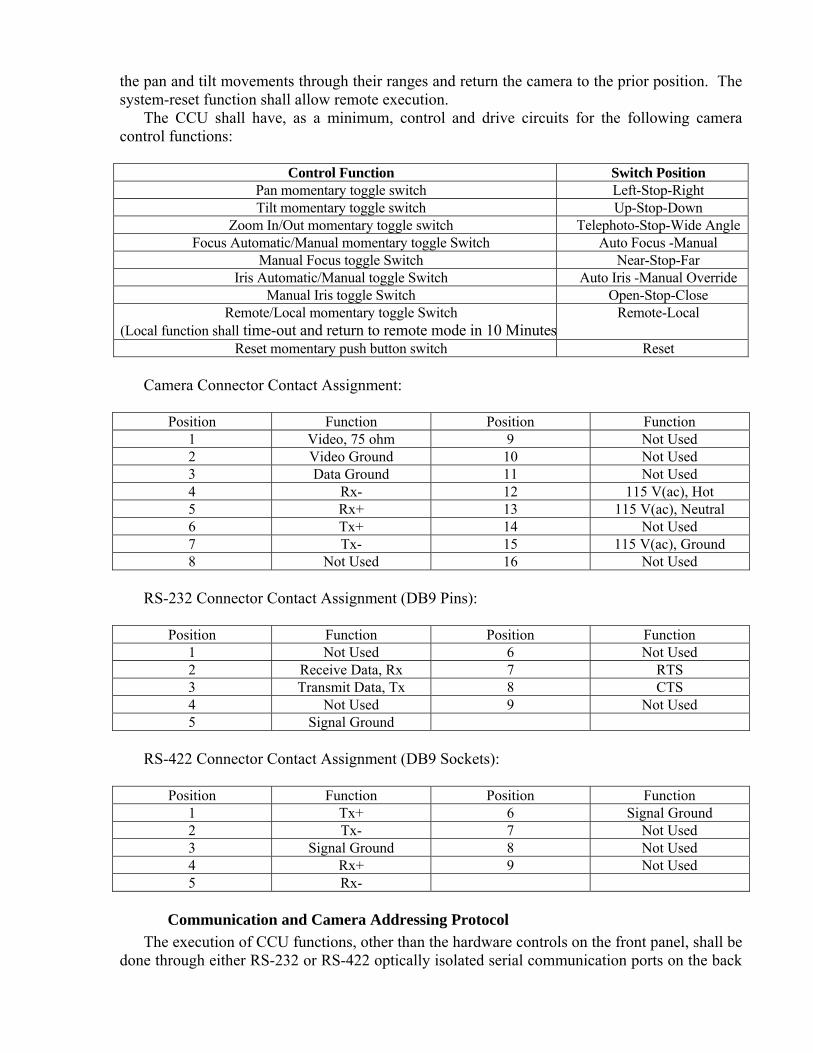
The CCU shall have, as a minimum, control and drive circuits for the following camera control functions:
Control Function Switch Position
Pan momentary toggle switch Left-Stop-Right Tilt momentary toggle switch Up-Stop-Down
Zoom In/Out momentary toggle switch Telephoto-Stop-Wide Angle Focus Automatic/Manual momentary toggle Switch Auto Focus -Manual
Manual Focus toggle Switch Near-Stop-Far Iris Automatic/Manual toggle Switch Auto Iris -Manual Override
Manual Iris toggle Switch Open-Stop-Close Remote/Local momentary toggle Switch
(Local function shall time-out and return to remote mode in 10 MinutesRemote-Local
Reset momentary push button switch Reset Camera Connector Contact Assignment:
Position Function Position Function 1 Video, 75 ohm 9 Not Used 2 Video Ground 10 Not Used 3 Data Ground 11 Not Used 4 Rx- 12 115 V(ac), Hot 5 Rx+ 13 115 V(ac), Neutral 6 Tx+ 14 Not Used 7 Tx- 15 115 V(ac), Ground 8 Not Used 16 Not Used
RS-232 Connector Contact Assignment (DB9 Pins):
Position Function Position Function 1 Not Used 6 Not Used 2 Receive Data, Rx 7 RTS 3 Transmit Data, Tx 8 CTS 4 Not Used 9 Not Used 5 Signal Ground
RS-422 Connector Contact Assignment (DB9 Sockets):
Position Function Position Function 1 Tx+ 6 Signal Ground 2 Tx- 7 Not Used 3 Signal Ground 8 Not Used 4 Rx+ 9 Not Used 5 Rx-
Communication and Camera Addressing Protocol
The execution of CCU functions, other than the hardware controls on the front panel, shall be done through either RS-232 or RS-422 optically isolated serial communication ports on the back

panel. A minimum 9,600-baud data rate shall be used. The CCU shall have a front panel RS-232 port for connection to a local laptop computer. The (NTCIP) 1205 MIB communications protocol shall be included.
The communications between CCU and the integrated camera unit shall be conducted through an EIA RS-422 circuit with full handshake support. A minimum 9,600-baud data rate shall be used. The CCU shall be 100 percent compatible with the protocol and data backbone architecture.
Power Consumption
The maximum power consumption for the CCU shall not exceed 45 W. Power consumption of equipment attached to CCU shall not exceed 250 W.
CCU to Laptop PC Cable
The Contractor shall furnish and install a universal serial bus (USB) to RS-232 serial adapter at each camera location. The adapter shall have a DB9 socket connector for RS-232 and Type A plug connector for USB. The Contractor shall also supply a 6 feet straight through USB extension cable. The USB function shall conform to version 2.0. The Contractor shall submit the adapter software in CD format.
ENVIRONMENTAL REQUIREMENTS Each CCU shall operate in an ambient temperature environment of –34 °C to +74 °C and up
to 90 percent relative humidity. Each CCU shall pass 5 Gs, 11 ms, in any axis under non-operating conditions, MIL-E-5400T, para 3.2.24.6 shock test. Each CCU shall pass vibration tests:
1. Sine vibration from 5 to 60 Hz with 0.082-inch total excursion without damage. 2. Random vibration from 60 to 1,000 Hz, 5 Gs RMS (0.027-G2/Hz) without damage.
10-3.__ VIDEO ENCODER UNIT
GENERAL A prototype of the video encoder unit (VEU) is not acceptable. All equipment shall be off-
the-shelf production units. All equipment shall be new and not previously used. The Contractor shall provide a Service and Operation manual describing the operation, maintenance of the VEU for each unit provided in the contract. The Contractor shall provide all necessary interface cables to connect communication equipment and the camera control unit (CCU) for a complete and successful installation and operation of the VEU, and as shown on the plans.
ABBREVIATIONS LED Light Emitting Diode AC Alternating Current SNMP Simple Network Management Protocol TELNET TELecommunication NETwork CLI Command Line Interface NTSC National Television System Committee SIF Source Input Format QSIF Quarter Source Input Format CIF Common Intermediate Format
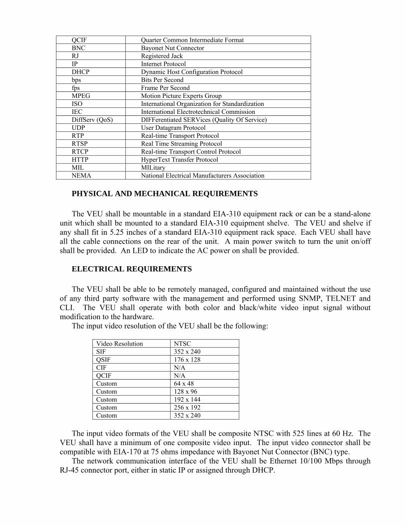
QCIF Quarter Common Intermediate Format BNC Bayonet Nut Connector RJ Registered Jack IP Internet Protocol DHCP Dynamic Host Configuration Protocol bps Bits Per Second fps Frame Per Second MPEG Motion Picture Experts Group ISO International Organization for Standardization IEC International Electrotechnical Commission DiffServ (QoS) DIFFerentiated SERVices (Quality Of Service) UDP User Datagram Protocol RTP Real-time Transport Protocol RTSP Real Time Streaming Protocol RTCP Real-time Transport Control Protocol HTTP HyperText Transfer Protocol MIL MILitary NEMA National Electrical Manufacturers Association PHYSICAL AND MECHANICAL REQUIREMENTS The VEU shall be mountable in a standard EIA-310 equipment rack or can be a stand-alone
unit which shall be mounted to a standard EIA-310 equipment shelve. The VEU and shelve if any shall fit in 5.25 inches of a standard EIA-310 equipment rack space. Each VEU shall have all the cable connections on the rear of the unit. A main power switch to turn the unit on/off shall be provided. An LED to indicate the AC power on shall be provided.
ELECTRICAL REQUIREMENTS The VEU shall be able to be remotely managed, configured and maintained without the use
of any third party software with the management and performed using SNMP, TELNET and CLI. The VEU shall operate with both color and black/white video input signal without modification to the hardware.
The input video resolution of the VEU shall be the following:
Video Resolution NTSCSIF 352 x 240QSIF 176 x 128CIF N/AQCIF N/ACustom 64 x 48Custom 128 x 96Custom 192 x 144Custom 256 x 192Custom 352 x 240
The input video formats of the VEU shall be composite NTSC with 525 lines at 60 Hz. The
VEU shall have a minimum of one composite video input. The input video connector shall be compatible with EIA-170 at 75 ohms impedance with Bayonet Nut Connector (BNC) type.
The network communication interface of the VEU shall be Ethernet 10/100 Mbps through RJ-45 connector port, either in static IP or assigned through DHCP.

The camera control data interface shall include a Maintenance Serial Port for local maintenance and a Control Serial Port for Data transport. The port shall be EIA-232 at a user selectable data rate from 1,200 to 56,000 bps, asynchronous. The connector type for the port shall be a DB9 pin type.
The VEU shall provide bandwidth for camera control within the bandwidth allocated for video only when bandwidth is needed for camera control/status data transmission.
The video compression of the VEU shall meet MPEG 4-ISO/IEC 14496-2 (1999) standard. The MPEG-4 compliant levels are:
1. Level 1 – up to 64 Kbps 2. Level 2 – up to 128 Kbps 3. Level 3 – up to 384 Kbps The video rates of the VEU shall be scaleable from 1 fps to 30 fps and from 8 Kbps to 2
Mbps. User selectable options are: 1. Constant Bit rate at Constant Frame rate 2. Variable Bit rate at Constant Frame rate 3. Constant Bit rate at Variable Frame rate The video delivery options of the VEU are either unicast or multicast with protocols DiffServ
(QoS), UDP, IP, RTP, RTSP, RTCP, HTTP, SNMP, TELNET and CLI. POWER REQUIREMENTS The VEU shall operate between voltage 89 V(ac) to 135 V(ac), 120 V(ac) nominal voltage
and 50 or 60 Hz (±3.0 Hz). The VEU shall conform to NEMA standard TS-2 (1998) for traffic control system 2.1.2. The VEU shall meet the requirements of Section 2.1.6 "transients, power service" of the NEMA standard TS-2 (1998). The line variation and surge performance shall be tested to meet these specifications by an outside agency, other than the VEU manufacturer. The test results shall be provided upon request. The power consumption shall not exceed a total 25 watts.
ENVIRONMENTAL REQUIREMENTS Each VEU shall operate in an ambient temperature environment of –20 °C to +70 °C and up
to 90 percent relative humidity. Each VEU shall pass 5 Gs, 11ms, in any axis under non-operating conditions, MIL-E-5400T, para 3.2.24.6 shock test. Each VEU shall pass vibration tests:
1. Sine vibration from 5 to 60 Hz with 0.082-inch total excursion without damage. 2. Random vibration from 60 to 1,000 Hz, 5 G's RMS (0.027-G2/Hz) without damage.
10-3.__ EQUIPMENT SHELF WITH BRACKETS
The Contractor shall furnish and install each equipment shelf as shown on the plans. Each shelf shall be furnished with 2 mounting brackets.

Each mounting bracket shall extend from the front to back mounting rails of the controller cabinet rack cage. Each bracket shall be designed to support a minimum of 50 lbs. The horizontal side of each bracket shall be a minimum of 3 inches. Each bracket shall be attached to front and rear of the rack cage with four (4) 10-32 stainless steel Phillips round head bolts.
Each shelf shall be fabricated of 0.125-inch cold rolled sheet or 0.125-inch aluminum sheet. Each shelf shall be the width of the control cabinet rack cage and 18 inches deep. Each shelf shall have equally distributed holes or slots throughout the shelf that shall provide 40 percent minimum open area for vertical flow-through ventilation. Each hole or slot shall not exceed 0.75-square inches in area. Each shelf shall be cadmium-plated or zinc-plated after cutting and drilling.
Each shelf shall be attached to the top of its pair of brackets in all four corners with stainless steel hardware, with the front of the shelf abutting against the front rail of the control cabinet rack cage. 10-3.__ HIGH MAST CAMERA INTERLOCK JUNCTION BOX
Interlock junction box (IJCB) shall be mounted inside the pole base and shall be accessible through the handhole. The IJCB shall be fabricated from 14 gauge steel sheet and hot-dipped galvanized after fabrication in accordance with the provisions in Section 75-1.05, "Galvanizing," of the Standard Specifications. All mounting nut and bolts shall be 1/4"-20 x 1" hex head stainless steel. Lockwashers shall be used with each bolt. The IJCB shall consist of a main circuit breaker, a flasher transfer relay and a box cable connector as shown on the plans. The flasher transfer relay shall conform to the provisions in Section 86-4.09C(6), "Dimming Relays" of the Standard Specifications.
The box cable connector shall be AMP 206036-1 receptacle with square flange housing type.
The contact assignment as following: a. Contact 12 to relay coil contact 1 b. Contact 13 to relay coil contact 2 c. Contact 15 to equipment ground d. All other contacts not used. The flasher transfer relay socket connector contact assignment as following: a. Contact 1 (relay coil) to box connector contact 12 b. Contact 2 (relay coil) to box connector contact 13 c. Contact 5 (Common, Circuit #1) to 115 V(ac) from Main Breaker d. Contact 7 (Normal Open, Circuit #1) to 115 V(ac) Winch Motor e. All other contacts not used.
10-3.__ HIGH MAST CAMERA POLE ASSEMBLY
GENERAL The Contractor shall furnish and install the following equipment for each high mast camera
assembly as described herein and as shown on the plans: 1. Camera lowering device 2. One high mast pole 3. One interlock junction box (IJCB)
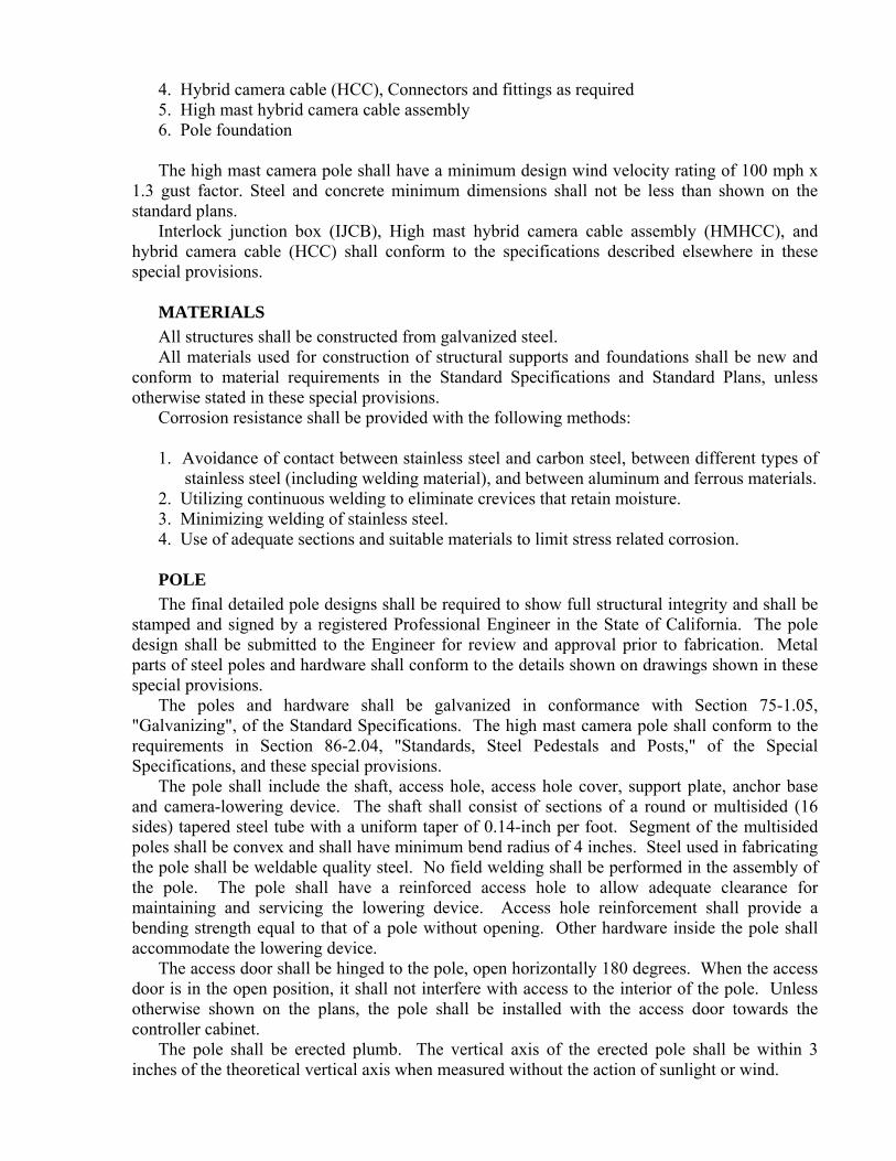
4. Hybrid camera cable (HCC), Connectors and fittings as required 5. High mast hybrid camera cable assembly 6. Pole foundation The high mast camera pole shall have a minimum design wind velocity rating of 100 mph x
1.3 gust factor. Steel and concrete minimum dimensions shall not be less than shown on the standard plans.
Interlock junction box (IJCB), High mast hybrid camera cable assembly (HMHCC), and hybrid camera cable (HCC) shall conform to the specifications described elsewhere in these special provisions.
MATERIALS All structures shall be constructed from galvanized steel. All materials used for construction of structural supports and foundations shall be new and
conform to material requirements in the Standard Specifications and Standard Plans, unless otherwise stated in these special provisions.
Corrosion resistance shall be provided with the following methods: 1. Avoidance of contact between stainless steel and carbon steel, between different types of
stainless steel (including welding material), and between aluminum and ferrous materials. 2. Utilizing continuous welding to eliminate crevices that retain moisture. 3. Minimizing welding of stainless steel. 4. Use of adequate sections and suitable materials to limit stress related corrosion. POLE The final detailed pole designs shall be required to show full structural integrity and shall be
stamped and signed by a registered Professional Engineer in the State of California. The pole design shall be submitted to the Engineer for review and approval prior to fabrication. Metal parts of steel poles and hardware shall conform to the details shown on drawings shown in these special provisions.
The poles and hardware shall be galvanized in conformance with Section 75-1.05, "Galvanizing", of the Standard Specifications. The high mast camera pole shall conform to the requirements in Section 86-2.04, "Standards, Steel Pedestals and Posts," of the Special Specifications, and these special provisions.
The pole shall include the shaft, access hole, access hole cover, support plate, anchor base and camera-lowering device. The shaft shall consist of sections of a round or multisided (16 sides) tapered steel tube with a uniform taper of 0.14-inch per foot. Segment of the multisided poles shall be convex and shall have minimum bend radius of 4 inches. Steel used in fabricating the pole shall be weldable quality steel. No field welding shall be performed in the assembly of the pole. The pole shall have a reinforced access hole to allow adequate clearance for maintaining and servicing the lowering device. Access hole reinforcement shall provide a bending strength equal to that of a pole without opening. Other hardware inside the pole shall accommodate the lowering device.
The access door shall be hinged to the pole, open horizontally 180 degrees. When the access door is in the open position, it shall not interfere with access to the interior of the pole. Unless otherwise shown on the plans, the pole shall be installed with the access door towards the controller cabinet.
The pole shall be erected plumb. The vertical axis of the erected pole shall be within 3 inches of the theoretical vertical axis when measured without the action of sunlight or wind.
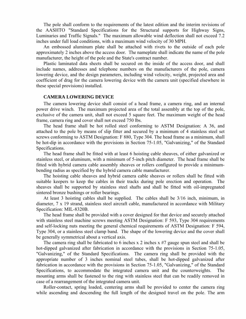
The pole shall conform to the requirements of the latest edition and the interim revisions of the AASHTO "Standard Specifications for the Structural supports for Highway Signs, Luminaries and Traffic Signals." The maximum allowable wind deflection shall not exceed 7.2 inches under full load conditions, with a maximum wind velocity of 30 MPH.
An embossed aluminum plate shall be attached with rivets to the outside of each pole approximately 2 inches above the access door. The nameplate shall indicate the name of the pole manufacturer, the height of the pole and the State's contract number.
Plastic laminated data sheets shall be secured on the inside of the access door, and shall include names, addresses and telephone numbers on the manufacturers of the pole, camera lowering device, and the design parameters, including wind velocity, weight, projected area and coefficient of drag for the camera lowering device with the camera unit (specified elsewhere in these special provisions) installed.
CAMERA LOWERING DEVICE The camera lowering device shall consist of a head frame, a camera ring, and an internal
power drive winch. The maximum projected area of the total assembly at the top of the pole, exclusive of the camera unit, shall not exceed 5 square feet. The maximum weight of the head frame, camera ring and cover shall not exceed 750 lbs.
The head frame shall be hot rolled steel conforming to ASTM Designation: A 36, and attached to the pole by means of slip fitter and secured by a minimum of 4 stainless steel set screws conforming to ASTM Designation: F 880, Type 304. The head frame as a minimum, shall be hot-dip in accordance with the provisions in Section 75-1.05, "Galvanizing," of the Standard Specifications.
The head frame shall be fitted with at least 6 hoisting cable sheaves, of either galvanized or stainless steel, or aluminum, with a minimum of 5-inch pitch diameter. The head frame shall be fitted with hybrid camera cable assembly sheaves or rollers configured to provide a minimum-bending radius as specified by the hybrid camera cable manufacturer.
The hoisting cable sheaves and hybrid camera cable sheaves or rollers shall be fitted with suitable keepers to keep the cables in their tracks during pole erection and operation. The sheaves shall be supported by stainless steel shafts and shall be fitted with oil-impregnated sintered bronze bushings or roller bearings.
At least 3 hoisting cables shall be supplied. The cables shall be 3/16 inch, minimum, in diameter, 7 x 19 strand, stainless steel aircraft cable, manufactured in accordance with Military Specification: MIL-8320B.
The head frame shall be provided with a cover designed for that device and securely attached with stainless steel machine screws meeting ASTM Designation: F 593, Type 304 requirements and self-locking nuts meeting the general chemical requirements of ASTM Designation: F 594, Type 304, or a stainless steel clamp band. The shape of the lowering device and the cover shall be generally symmetrical about a vertical axis.
The camera ring shall be fabricated to 6 inches x 2 inches x #7 gauge spun steel and shall be hot-dipped galvanized after fabrication in accordance with the provisions in Section 75-1.05, "Galvanizing," of the Standard Specifications. The camera ring shall be provided with the appropriate number of 3 inches nominal steel tubes, shall be hot-dipped galvanized after fabrication in accordance with the provisions in Section 75-1.05, "Galvanizing," of the Standard Specifications, to accommodate the integrated camera unit and the counterweights. The mounting arms shall be fastened to the ring with stainless steel that can be readily removed in case of a rearrangement of the integrated camera unit.
Roller-contact, spring loaded, centering arms shall be provided to center the camera ring while ascending and descending the full length of the designed travel on the pole. The arm

system shall be capable of keeping the ring concentric with pole in the winds up to 30 MPH. The rollers for the centering arms shall be of a water resistant, non-marking material. All axle shafts for arms and rollers shall be of stainless steel conforming to ASTM Designation: A 276, Type 304. The arms system shall not allow the pole to be inadvertently wedged between the rollers and the camera ring. Ultimate support of the camera ring shall not be lost by an individual or total spring failure.
Provisions shall be made for leveling the camera ring while in lowered position. The Contractor shall level and balance the camera support ring upon installation and again before completion of the contract.
The transition assembly shall be fabricated from A36 steel. The camera ring shall be supported by three stainless steel 7 x 19 strands, 1/4-inch minimum diameter aircraft cable manufactured per MIL-8320B. Each cable shall be fitted with a stainless steel fitting which enables it to develop the full strength of the cable. The fitting shall attach to the transition assembly within the pole shaft without the use of springs. A ball bearing swivel, of sufficient size to sustain the loading on the cable, with a safety factor of four to allow the attitude of the aircraft cable to be relieved as the camera ring is raised and lowered. The lift cable shall pass up through the pole shaft, over the stainless steel head frame sheaves, to the camera ring, where they are led through guides and a compression ring and terminated with a collar-type strand vice device. The compression springs, while supporting the camera ring, are not relied upon for support of the ring in case of spring failure.
The safety mechanism shall be located in the base of the pole and consist of multi-point safety chain and hook assemblies to maintain the tension on the transition assembly, allowing the winch assembly to be disengaged. Chain and hooks shall be hot-dipped galvanized after fabrication in accordance with the provisions in Section 75-1.05, "Galvanizing," of the Standard Specifications. Each chain shall be secured to a plate welded to the inside of the pole shaft. The safety mechanism shall be self-contained within the pole and independent of the anchor bolt and pole foundation. Top latch units shall not be acceptable.
The internal mechanism shall be capable of raising or lowering the camera ring at an approximate speed of 11 feet/min. The winch shall be furnished with 1/4-inch minimum diameter, 7 x 19 strand stainless steel aircraft cable, conforming to Military Specification: MIL-8320B, of sufficient length to maintain at least four wraps around the drum with the camera ring unit fully lowered position. The free end of the winch cable shall be finished with a stainless steel compression sleeve sufficient to develop 95 percent of the rated load capacity of the assembly through a ball bearing swivel of sufficient size to sustain the loading of the cable factor of four. The transition design shall be such to prevent twisting of the support cables to assure smooth winding of the cables on the winch and to prevent binding on the inside of the tower shaft. Winch cable shall wind uniformly.
The internal power drive winch unit shall include: 1. A heavy duty, totally enclosed, fan cooled, reversible universal type motor, rated at 115 V
(ac) 746 W, minimum, for continuous duty, and provided with overcurrent protection. 2. An adjustable torque limiter with ball or roller bearings on all rotating shafts. 3. A remote control reversing switch (labeled "UP" and "DOWN") with minimum 20 feet
cord. 4. Worm-gear driven winch. 5. Mounting frame. 6. Other equipment as necessary.

All internal power drive winch unit components, including transformer and interlock junction box, shall be removable through the access hole for repair or replacement.
FOUNDATION The foundation shall conform to the requirements for cast-in-drill-hole concrete piles in
Section 86-2.03, "Foundation," of the Standard Specifications. SUBMITTALS Submittals for the high mast camera pole assembly shall conform to the requirements in
Section 86-1.03, "Equipment List and Drawings," of the Standard Specifications and these special provisions. Submittals shall be delivered to the Engineer prior to the erection of the high mast camera assembly.
The Contractor shall submit descriptive data, design working drawings, erection working drawings, calculations, and a list of materials used for the high mast camera assembly. The material list shall be complete as to the name of manufacturer, catalog number, size, capacity, finish, pertinent ratings, and identification symbols used on the plans or in the special provisions for each unit. Each submittal shall consist of 5 copies. Plans and detailed drawings shall not be larger than 22" x 34". Each separate item submitted shall bear the descriptive title and the State's contract number.
INSPECTION & TESTING All equipment furnished by the Contractor shall be subject to monitoring and testing to
determine conformance with all applicable requirements and to ensure proper operation of the camera lowering device prior to final acceptance of the project. Documentation as required demonstrating performance and operation in conformance to these special provisions shall be furnished by the Contractor as part of this project. All equipment required for conducting tests shall be supplied and retained by the Contractor. No separate payment will be made for the monitoring, testing, test equipment, and documentation of test results, but shall be included in the amount bid for other pay items.
The State reserves the right to examine and test any or all materials furnished by the Contractor (using the test equipment supplied by the Contractor) for this project to determine if they meet these special provisions and the Standard Specifications.
If any material used in the construction of this project is defective or otherwise unsuitable, or the workmanship does not conform to the accepted standards, the Contractor shall replace such defective parts and material at no cost to the State.
The Contractor may offer rejected equipment again for consideration provided all non-compliance has been corrected and pretested by the Contractor.
The camera-lowering device shall be submitted for inspection and testing. Inspection and testing shall be performed at a site in California approved by the Engineer. Notification shall be given to the Engineer at least 10 days prior to demonstration. The times and dates of the tests shall be approved by the Engineer. The Contractor shall conduct all tests in the presence of the Engineer. Testing shall only take place on weekdays as specified elsewhere in the special provisionsPrior to acceptance of the contract, a trained manufacturer's representative shall perform the operational testing of the high mast camera assembly. The testing shall consist of a minimum of 3 complete cycles of raising and lowering the camera ring (complete with the integrated camera unit connected to hybrid camera cable) the full length of its travel, as designed, within one working day. Notification shall be given to the Engineer at least 10 days prior to testing.

DOCUMENTATION & TRAINING After the high mast camera assembly is in operation, The Contractor shall provide an
instructional digital video in Audio Video Interleave (AVI) format on a minimun 8 GB USB version 2.0 flash drive or a Secure Digital (SD) card, complete written instructions, and a demonstration to State Maintenance personnel on the maintenance of the high mast camera assembly, including leveling of the camera ring and the procedures for the safe raising and lowering of the camera ring.
Spare parts, parts lists, and the operating, maintenance and service instructions, packaged with or accompanying the equipment installed on the project, shall be delivered to the Engineer prior to acceptance of the project. 10-3.__ HIGH MAST HYBRID CAMERA CABLE ASSEMBLY
The High mast hybrid camera cable (HMHCC) assembly shall consist of one RG-59/U type
analog video coaxial cable, one Category 5E cable, one 3-No. 22 AWG conductor cable, one 4-No. 16 AWG conductor cable in a common outer jacket. The high mast hybrid camera cable cross-section is shown on the plans.
The Coaxial cable shall conform to:
Electrical Coax Capacitance (picofarads/ft nominal) 17.3 Impedance (ohms-nominal) 75 Velocity of propagation (nominal) 78 percent Nominal Diameter (inch) 0.242 Insulation Rating 300V
The cable attenuation at 20 °C shall measure at maximum as:
Frequency (MHz) Nominal dB/ 100 ft 1 0.30 10 0.90 50 2.10
The coaxial cable physical measurements:
Component Nominal O.D. (inches) Copper center conductor 0.040 Foam polyethylene dielectric 0.180 Sealed APA tape with 0.06-inch overlap 0.216 Woven aluminum braid 0.241 PVC outer jacket 0.297
(APA = Aluminum polyolefin and aluminum with adhesive) The Category 5E cable shall consist of four unshielded twisted pairs (UTP) No. 24 AWG
solid copper conductors insulated with Polyolefin (PO). The insulated conductors shall be tightly twisted into individual pairs and jacketed with PVC. The cable shall have a nominal O.D. of 0.26". The cable shall be compliant with EIA/TIA-568B Category 5E standards. The

maximum DC resistance shall be 0.027 Ω/ft at 20 °C. The mutual capacitance shall be 13.65 pF/ft nominal. The characteristics impedance shall be 100 Ω ±15 percent from 1 MHz to 100 MHz. The insulation rating of each conductor shall be 300 V.
The cable shall be color coded as follows:
PAIR COLOR CODE (TIP//RING) 1 White/Blue Stripe // Blue 2 White/Orange Stripe // Orange 3 White/Green Stripe // Green 4 White/Brown Stripe // Brown The 3-No 22 AWG shall be stranded 7 x 30, tinned copper insulated with 0.016" nominal
wall of S-R PVC and a nominal O.D. of 0.062". The insulation rating of each conductor shall be 600 V. The 3 conductors shall be color coded as follows:
1. Red 2. Blue 3. Orange The 4-No. 16 AWG shall be stranded 19 x 29, tinned copper insulated with 0.016" nominal
wall of S-R PVC and a nominal O.D. of 0.088". The insulation rating of each conductor shall be 600 V. The 4 conductors shall be color coded as follows:
1. Black 2. White 3. Yellow 4. Green The HMHCC assembly shall also have a 36 AWG tinned copper braid with 90 percent
coverage, an O/A binder of 0.001" polyester 25 percent overlap, and an outer jacket conforming to: color to match Fed-Std-595 color #24091, material 0.035" brown PVC to 0.600" O. D. and must pass the VW-1 vertical flame test. Fillers shall be used as required to form a uniform round cable. The insulation rating of the overall cable jacket shall be 300 V. The manufacture identification shall be surface printed in white ink every foot along the length of the cable.
The HMHCC assembly shall be continuous and with sufficient length based on the pole height denoted by the pole type as shown on the plans.
The HMHCC assembly shall be factory terminated with cable connectors on both ends. Connector AMP 206036-3 with a full set crimp contact pins and strain relief back shell, AMP 206070-1 shall be installed on the cable end toward camera control unit. Connector AMP 206037-1 with a full set crimp contact sockets and strain relief back shell, AMP 206070-1 shall be installed on the cable end toward the integrated camera unit. All connector contact shall be constructed with brass contact body material and with stainless steel spring that are sub-plated with 0.000050-inch nickel and plated with 0.000030-inch gold. Contact size shall be 16.
10-3.__ SERVICE MANUAL REQUIREMENTS
The Contractor shall provide to the Engineer a minimum of 3 copies of service manuals for the integrated camera unit, camera control unit (CCU), video encoder unit (VEU) under this special provisions. Each manual shall contain the following sections and sub-sections.

General information section a. A list of applicable subassemblies that comprise the specified equipment. b. Overall description of the equipment design features (including all enhance features if
applicable), performance, and applications. c. Equipment specifications summary. d. Equipment installation instructions. Theory of operations section a. Theory of operation of the standard equipment, with unique or unusual circuitry described
in detail. b. Theory of operation reflecting any modifications to the standard equipment. Maintenance section a. Recommended test equipment and fixtures, or minimum operational and performance
requirements for appropriate test equipment. b. Trouble shooting information and charts. c. Removal and installation procedures for replacing assemblies and subassemblies, if not
obvious or if improper sequencing of steps may result in component damage. Replacement parts section a. Each manual shall contain an equipment replacement parts list including electrical parts,
mechanical parts and assemblies. b. All semiconductors shall be identified by the supplier's numbers and by Joint Electron
Device Council (JEDEC) numbers if applicable. Diagram section a. Schematic diagram(s) identifying all circuit components and showing normal test voltages
and levels. b. An overall functional block diagram. c. Detailed interconnecting diagram(s) showing wiring between modules, circuit boards and
major components. d. Pictorial circuit board layout diagram(s) showing both component placement and printed
wiring detail. e. Diagram(s) showing location of circuit boards and other subassemblies. f. Exploded view diagram(s) of complex mechanical assemblies. Physical requirements a. All pages, including latest revisions, shall be securely fastened together between
protective covers (loose-leaf ring binding is acceptable). b. No page shall be subject to fading from exposure to any normal source of ambient lighting
(ozalid reproduced pages are not acceptable). 10-3.__ TRAFFIC OPERATIONS SYSTEM EQUIPMENT TESTING
Prior to shipping to the project, the Contractor shall submit the following items to the State of California, Department of Transportation Laboratory, 5900 Folsom Blvd, Sacramento, CA 95819 for acceptance testing:

1. Integrated Camera Unit 2. Camera Control Unit (CCU) 3. Video Encoder Unit (VEU) 4. High Mast Camera Lowering Device System 5. Fiber Optic Transmitter And Receiver 6. Extinguishable Message Sign Panels 7. Remote traffic microwave sensor (RTMS) system Approximately 30 days will be required for the testing. The Contractor will be notified upon
completion of the testing and shall arrange for delivery of the equipment to a storage location designated by the Contractor. The Contractor is responsible for the costs of such testing and the transportation to and from the Laboratory.
In addition to the above items, the Contractor shall submit all additional equipment listed
elsewhere in these special provisions to the Laboratory for acceptance testing. Approximately 30 days will be required for the testing. Upon satisfactory completion of the
testing, the Contractor shall pick up the equipment from the Laboratory and deliver to a State-owned storage location designated by the Engineer.

The contract lump sum price paid for traffic operations system at various locations shall include full compensation for furnishing all labor, materials (except items covered by other bid items), tools, equipment, and incidentals, and for doing all the work involved in installing traffic operations system, complete in place, including all the foundations (except for the changeable message sign), poles, manuals and testing, as shown on the plans, as specified in the Standard Specifications and these special provisions, and as directed by the Engineer.
The contract unit price paid for the additional equipment as specified in these special provisions shall be paid for under separate bid items.
The contract unit price paid for each of the following items shall include full compensation for furnishing all materials, tools, equipment, and incidentals, as shown on the plans, as specified in these special provisions, and as directed by the Engineer:
1. Integrated Camera unit 2. Camera control unit (CCU) 3. Video encoder unit (VEU) 4. Dial-up modem 5. Extinguishable message sign radio cntroller assembly 6. Extinguishable message sign panel (LED) 7. Extinguishable message sign panel 8. Highway advisory radio system 9. General packet radio system (GPRS) wireless modem assembly 10. Master traffic controller unit (MTCU) 11. Analog video routing switcher (AVS -including training) 12. Access node 13. Channel service unit/ data service unit (CSU/DSU) 14. Short haul modem (SHM) 15. Fiber optic transmitters and receivers (FOTS/FORS) 16. Multimode fiber optic transmitters and receivers (MMFORS/MMFOTS) 17. Fiber optic data modem (FODM) 18. Uninterruptable power system (UPS) 19. Maintenance bypass switch (MBS) 20. Long Lead-in cable Loop Detector (LLLD) sensor unit 21. Video image processing system (VIPS) 22. Video monitor 23. Analog data station termination (ADST) The contract price paid in feet for each of the following items shall include full compensation
for furnishing the materials as shown on the plans, as specified in these special provisions, and as directed by the Engineer:
1. Fiber optic cable.