10-31-228-01 gsr finalntwfp.torranceprojects.city/shared documents/attachme… · ·...
TRANSCRIPT


Geotechnical Study Report North Torrance Wellfield Project
Torrance, California August 11, 2011
Page iii
Converse Consultants
CCMON\JOBFILES\2010\31\228\10-31-228-01_GSR
EXECUTIVE SUMMARY
The following is the summary of our Geotechnical Study Report with our findings, conclusions, and recommendations presented in the body of this report. Please refer to the appropriate sections of this Geotechnical Study Report for more detailed discussion of our conclusions and recommendations. In the event of a conflict between this executive summary and the report, or an omission in the summary, the report content shall prevail. The North Torrance Wellfield Project consists of the following elements:
1. Well No. 10 within the 1.5 acre parcel west of Yukon Elementary School.
2. Booster Pump Station and Utility building within the 1.5 acre parcel west of Yukon Elementary School.
3. One three-million-gallon storage tank within the 1.5 acre parcel west of Yukon Elementary School.
4. Well No. 11 planned southeast of Yukon Elementary School within an approximately 40-foot-wide strip of level land at the top of a 3- to 8-foot-high descending slope.
5. New water pipelines to connect existing Well No. 9 at McMaster Park and planned Well No. 11 with the proposed storage tank site west of Yukon Elementary School.
6. New drain pipeline installed below the Caltrans Right-of-Way (Interstate 405) for connection from the storage tank pipeline easement to the existing storm drain system located near the intersection of Yukon Avenue and W. 182nd Street.
Our subsurface exploration was performed with the aid of truck-mounted hollow-stem auger borings drilled between depths of approximately 16.5 to 31.5 feet below existing grades.
In general, soils below the well sites and planned pipeline alignments consist of relatively firm to stiff clay, based on soil type classification and sampling blow-count correlation. Undocumented fill soils ranging in depth from approximately 6.5 to 11.5 feet were encountered in the area of the proposed storage tank and booster pump/utility building. Remedial grading will be needed for foundation support.
Groundwater levels monitored since 1949 have been recorded at depths of 75 feet or deeper from the ground surface. Groundwater was not encountered in the borings drilled to depths of up to 31.5 feet below grade. In general, groundwater is anticipated to fluctuate with seasonal variations but is not anticipated during construction of the planned improvements.
The upper five (5) feet of native site soils sampled and tested have a medium expansion potential, and the upper five (5) feet of undocumented fill soils sampled and
Geotechnical Study Report North Torrance Wellfield Project
Torrance, California August 11, 2011
Page iv
Converse Consultants
CCMON\JOBFILES\2010\31\228\10-31-228-01_GSR
tested have a very low expansion potential. Expansive soil mitigation measures for improvements supported on future fill soils derived from on-site and imported sources are recommended.
Site soils (undocumented fill and native) have concentrations of water soluble sulfates considered non-corrosive to concrete.
Laboratory testing indicates that site soils (undocumented fill and native) are considered potentially corrosive to ferrous metals.
The fine-grained soils (undocumented fill and native) below the area of the planned storage tank and booster pump/utility building were tested for collapse/consolidation, with the test results indicating a moderate potential for consolidation under saturated conditions.
The site is not located within a mapped Seismic Hazard Zone for either liquefaction or slope instability.
There are no known active faults projecting toward or extending across the proposed site. The site is not situated within a currently designated Earthquake Fault Zone for ground rupture hazard.
Although clear of geologic hazards associated with fault ground rupture, liquefaction, and slope instability, the site is located within a seismically active area and will be subject to intense ground motion during a significant seismic event. Site-specific parameters have been calculated in general accordance with the 2010 California Building Code.
The planned at-grade structures for well equipment, storage tank and booster pump/utility building can be supported on shallow footings or slab-on-grade bearing on compacted fill. Buildings can be supported on shallow footings bearing on future compacted fill.
Site preparation for well structures will require over-excavation on the order of 2 feet from existing grade for support of concrete pads. The remedial grading should extend at least 2 feet beyond the well foundation slab.
Site preparation for proposed storage reservoir tank and booster pump/utility building will require over-excavation and placement of compacted fill for support of concrete pads and foundations. Over-excavation for reservoir should be at least 8 feet below existing grade, or to the depth of fill, whichever is deeper. Over-excavation for building should be at least 12 feet below existing grade, or to the depth of fill, whichever is deeper.
It is expected that the near-surface site soils can be excavated with conventional heavy-duty earth-moving equipment in good working condition. Shoring or sloped excavations should be anticipated for excavations deeper than approximately 5 feet. Excavated site soils free of organic matter and demolition debris are considered

Geotechnical Study Report North Torrance Wellfield Project
Torrance, California August 11, 2011
Page v
Converse Consultants
CCMON\JOBFILES\2010\31\228\10-31-228-01_GSR
suitable for placement as compacted fill after proper processing. Such processing may include moisture conditioning and mixing, and removal/screening of oversized debris.
Results of our study indicate that the areas of planned site improvements are suitable for the proposed development from a geotechnical standpoint, provided that the recommendations contained in this report (including over-excavation) are incorporated into the design and construction of the various projects discussed herein.
Geotechnical Study Report North Torrance Wellfield Project
Torrance, California August 11, 2011
Page vi
Converse Consultants
CCMON\JOBFILES\2010\31\228\10-31-228-01_GSR
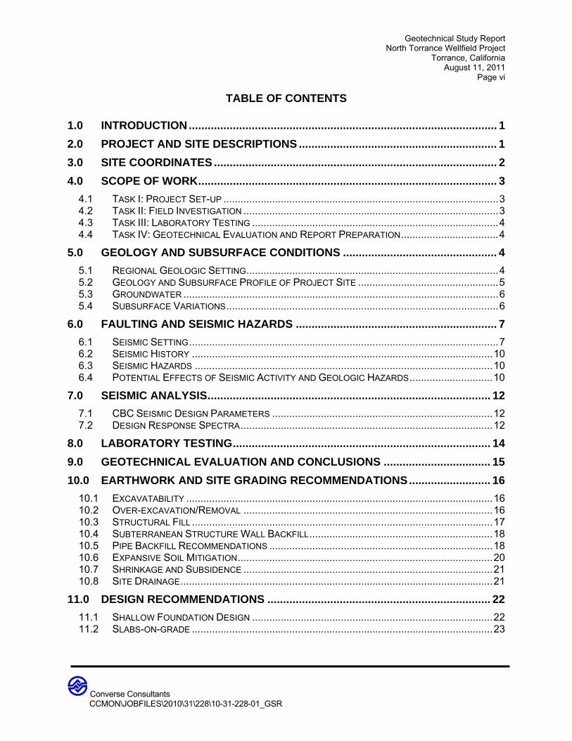
TABLE OF CONTENTS
1.0 INTRODUCTION .................................................................................................. 1
2.0 PROJECT AND SITE DESCRIPTIONS ............................................................... 1
3.0 SITE COORDINATES .......................................................................................... 2
4.0 SCOPE OF WORK ............................................................................................... 3
4.1 TASK I: PROJECT SET-UP ................................................................................................ 3 4.2 TASK II: FIELD INVESTIGATION ......................................................................................... 3 4.3 TASK III: LABORATORY TESTING ...................................................................................... 4 4.4 TASK IV: GEOTECHNICAL EVALUATION AND REPORT PREPARATION .................................. 4
5.0 GEOLOGY AND SUBSURFACE CONDITIONS ................................................. 4
5.1 REGIONAL GEOLOGIC SETTING ........................................................................................ 4 5.2 GEOLOGY AND SUBSURFACE PROFILE OF PROJECT SITE ................................................. 5 5.3 GROUNDWATER .............................................................................................................. 6 5.4 SUBSURFACE VARIATIONS ............................................................................................... 6
6.0 FAULTING AND SEISMIC HAZARDS ................................................................ 7
6.1 SEISMIC SETTING ............................................................................................................ 7 6.2 SEISMIC HISTORY ......................................................................................................... 10 6.3 SEISMIC HAZARDS ........................................................................................................ 10 6.4 POTENTIAL EFFECTS OF SEISMIC ACTIVITY AND GEOLOGIC HAZARDS ............................. 10
7.0 SEISMIC ANALYSIS .......................................................................................... 12
7.1 CBC SEISMIC DESIGN PARAMETERS ............................................................................. 12 7.2 DESIGN RESPONSE SPECTRA ........................................................................................ 12
8.0 LABORATORY TESTING .................................................................................. 14
9.0 GEOTECHNICAL EVALUATION AND CONCLUSIONS .................................. 15
10.0 EARTHWORK AND SITE GRADING RECOMMENDATIONS .......................... 16
10.1 EXCAVATABILITY ........................................................................................................... 16 10.2 OVER-EXCAVATION/REMOVAL ....................................................................................... 16 10.3 STRUCTURAL FILL ......................................................................................................... 17 10.4 SUBTERRANEAN STRUCTURE WALL BACKFILL ................................................................ 18 10.5 PIPE BACKFILL RECOMMENDATIONS .............................................................................. 18 10.6 EXPANSIVE SOIL MITIGATION ......................................................................................... 20 10.7 SHRINKAGE AND SUBSIDENCE ....................................................................................... 21 10.8 SITE DRAINAGE ............................................................................................................. 21
11.0 DESIGN RECOMMENDATIONS ....................................................................... 22
11.1 SHALLOW FOUNDATION DESIGN .................................................................................... 22 11.2 SLABS-ON-GRADE ......................................................................................................... 23
Geotechnical Study Report North Torrance Wellfield Project
Torrance, California August 11, 2011
Page vii
Converse Consultants
CCMON\JOBFILES\2010\31\228\10-31-228-01_GSR
11.3 MODULUS OF SUBGRADE REACTION .............................................................................. 23 11.4 RETAINING WALL DESIGN .............................................................................................. 24 11.5 STRUCTURAL PAVEMENT RECOMMENDATIONS ............................................................... 25 11.6 SOIL CORROSIVITY EVALUATION .................................................................................... 25 11.7 SITE DRAINAGE ............................................................................................................. 26 11.8 SOIL PARAMETERS FOR PIPE DESIGN ............................................................................ 27 11.9 BEARING PRESSURE FOR ANCHOR AND THRUST BLOCKS ............................................... 27 11.10 MODULUS OF SOIL REACTION (E’) ............................................................................. 28
12.0 CONSTRUCTION RECOMMENDATIONS ........................................................ 28
12.1 GENERAL ...................................................................................................................... 28 12.2 TEMPORARY EXCAVATIONS ........................................................................................... 28 12.3 SPECIAL CONSIDERATION FOR EXCAVATION ADJACENT TO EXISTING STRUCTURES ........ 29 12.4 TEMPORARY SHORING .................................................................................................. 30 12.5 TRENCHLESS CONSTRUCTION ....................................................................................... 31 12.6 GEOTECHNICAL SERVICES DURING CONSTRUCTION ....................................................... 32
13.0 CLOSURE .......................................................................................................... 33
14.0 REFERENCES ................................................................................................... 34
Tables
Page No.
Table No. 1, Summary of North Torrance Wellfield Project………..…………………………...... 2Table No. 2, Summary of Soil Profile and Boring Locations………..…………………………...... 5Table No. 3, Summary of Regional Faults……………….…………..…………………………...... 8Table No. 4, CBC Seismic Parameters.....….……………………………….….…………………. 12Table No. 5, Site-Specific Design Response Spectra Data.....….…………………………….… 13Table No. 6, Site-Specific Design Parameters ………………………………………................... 14Table No. 7, Earth Pressures for Retaining Wall Design………………………………….……... 24Table No. 8, Flexible Pavement Structural Sections…………………….……….………………. 25Table No. 9, Corrosivity Test Results……………………………………………………………… 26Table No. 10, Modulus of Soil Reaction…………………………………………………………… 28Table No. 11, Slope Ratios For Temporary Excavation…………………………………………… 29

Geotechnical Study Report North Torrance Wellfield Project
Torrance, California August 11, 2011
Page viii
Converse Consultants
CCMON\JOBFILES\2010\31\228\10-31-228-01_GSR
Drawings Following Page No. Drawing No. 1, Site Location Map…………….………………………….…………………….…… 1Drawing No. 2a thru 2e, Site Plan and Boring Location……..…………………………….……. 1Drawing No. 3, Regional Geologic Map…….……………………………………………….……. 5Drawing No. 4, Southern California Regional Fault Map…………………….…………..…….... 6Drawing No. 5, Site-Specific Design Response Spectra……………….…..………………...…… 13
Appendices Appendix A………………………………………………………………….…………..Field Exploration Appendix B ……………………………………………………………....Laboratory Testing Program Appendix C………………………………………………………………..…..Earthwork Specifications

Geotechnical Study Report North Torrance Wellfield Project
Torrance, California August 11, 2011
Page 1
Converse Consultants
CCMON\JOBFILES\2010\31\228\10-31-228-01_GSR
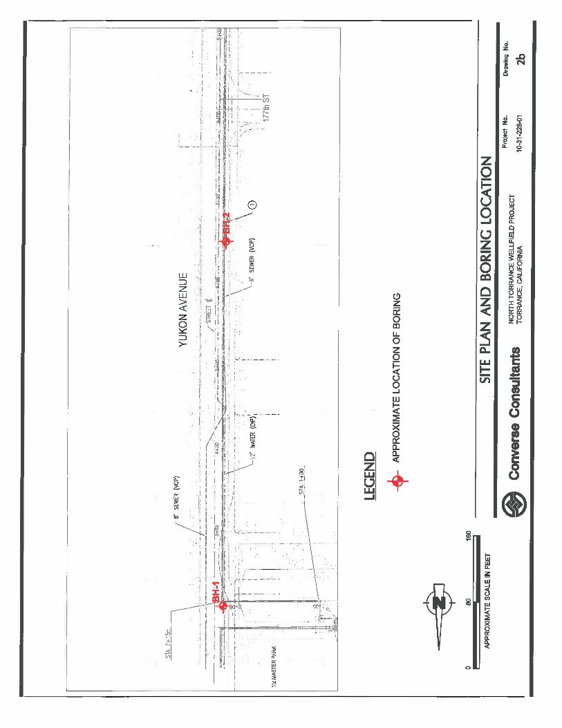
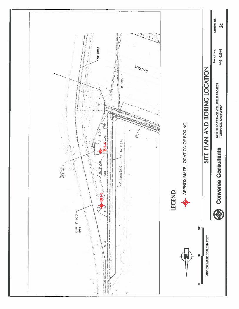
1.0 INTRODUCTION This report contains the findings and recommendations of our geotechnical study performed for the proposed North Torrance Wellfield Project located in Torrance, California, as illustrated on Drawing No. 1, Site Location Map. The purpose of this Geotechnical Study Report is to provide the results of our background review, subsurface exploration, laboratory testing, and geotechnical analyses, and to present geologic and geotechnical design parameters for use by the project design team. This report is written for the major project elements described herein, illustrated on Drawing Nos. 2a through 2e, Approximate Location of Borings, and listed on Table No. 1, Summary of North Torrance Wellfield Project. The findings and recommendations of this Geotechnical Study Report are intended for use solely by AECOM and the project design team. This report should not be used as a bidding document but may be made available to the potential contractors for information on factual data only. For bidding purposes, the contractors should be responsible for making their own interpretation of the data contained in this report. 2.0 PROJECT AND SITE DESCRIPTIONS The main area of the proposed North Torrance Wellfield Project is located on a triangular shaped, 1.5 acre parcel of undeveloped land located adjacent to and west of Yukon Elementary School. The parcel is bound by to the north by a Southern California Edison (SCE) transmission line easement and to the southwest and south by a Caltrans right-of-way for Interstate 405. Existing site topography is relatively flat. A summary of the various elements of the planned North Torrance Wellfield Project are listed on the following table:


Geotechnical Study Report North Torrance Wellfield Project
Torrance, California August 11, 2011
Page 2
Converse Consultants
CCMON\JOBFILES\2010\31\228\10-31-228-01_GSR
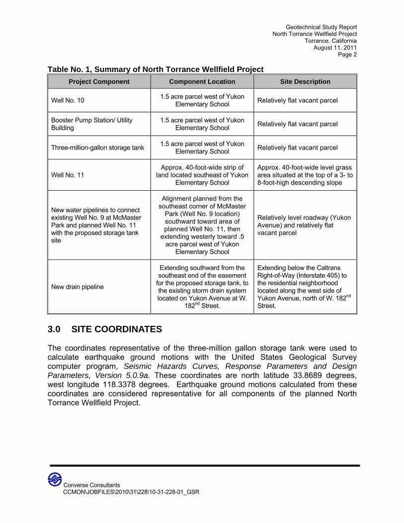
Table No. 1, Summary of North Torrance Wellfield Project
Project Component Component Location Site Description
Well No. 10 1.5 acre parcel west of Yukon
Elementary School Relatively flat vacant parcel
Booster Pump Station/ Utility Building
1.5 acre parcel west of Yukon Elementary School
Relatively flat vacant parcel
Three-million-gallon storage tank 1.5 acre parcel west of Yukon
Elementary School Relatively flat vacant parcel
Well No. 11 Approx. 40-foot-wide strip of
land located southeast of Yukon Elementary School
Approx. 40-foot-wide level grass area situated at the top of a 3- to 8-foot-high descending slope
New water pipelines to connect existing Well No. 9 at McMaster Park and planned Well No. 11 with the proposed storage tank site
Alignment planned from the southeast corner of McMaster
Park (Well No. 9 location) southward toward area of planned Well No. 11, then
extending westerly toward .5 acre parcel west of Yukon
Elementary School
Relatively level roadway (Yukon Avenue) and relatively flat vacant parcel
New drain pipeline
Extending southward from the southeast end of the easement
for the proposed storage tank, to the existing storm drain system located on Yukon Avenue at W.
182nd Street.
Extending below the Caltrans Right-of-Way (Interstate 405) to the residential neighborhood located along the west side of Yukon Avenue, north of W. 182nd Street.
3.0 SITE COORDINATES The coordinates representative of the three-million gallon storage tank were used to calculate earthquake ground motions with the United States Geological Survey computer program, Seismic Hazards Curves, Response Parameters and Design Parameters, Version 5.0.9a. These coordinates are north latitude 33.8689 degrees, west longitude 118.3378 degrees. Earthquake ground motions calculated from these coordinates are considered representative for all components of the planned North Torrance Wellfield Project.

Geotechnical Study Report North Torrance Wellfield Project
Torrance, California August 11, 2011
Page 3
Converse Consultants
CCMON\JOBFILES\2010\31\228\10-31-228-01_GSR
4.0 SCOPE OF WORK Our scope of work has consisted of the following tasks: 4.1 Task I: Project Set-up Converse obtained an excavation permit from the City of Torrance Community Development Department prior to initiating the subsurface exploration. Coordination and preparation of traffic control plans were also performed by Converse as a part of the permit acquisition. After obtaining the City permit, a Converse representative visited the site to mark the boring locations for utility clearance. Eight (8) boring locations (BH-1 through BH-8) were marked within the proposed project areas. Underground Service Alert of Southern California (USA) was notified of our proposed drilling locations 48 hours prior to initiation of the subsurface field work. 4.2 Task II: Field Investigation Subsurface exploration and soil sampling was performed to evaluate the soil conditions in the areas of planned North Torrance Wellfield Project improvements. The number and locations of the borings were based in part on the Request for Proposal (RFP) to Provide Preliminary Design Services for the North Torrance Wellfield Project issued by the City of Torrance on April 28, 2010. The planned project has been modified since issuance of the RFP, therefore number and locations of the exploratory borings outlined in our May 17, 2010 proposal were also modified to better serve the needs of the project. Our field exploration consisted of drilling, logging, and sampling eight (8) hollow-stem auger borings (BH-1 through BH-8) on July 7 and 8, 2011. The borings were drilled using truck mounted drilling equipment to depths of 16.5 to 31.5 feet below the existing ground surface (bgs). The boring locations are shown on Drawing Nos. 2a through 2e, Approximate Location of Borings. The borings were visually logged by our staff and sampled at regular intervals and at changes in subsurface soils conditions. California Modified Sampler (Ring samples), Standard Penetration Test samples, and bulk soil samples were obtained for laboratory testing. The borings were backfilled with soil cuttings and 1-sack slurry cement following the completion of drilling. Paved surface areas were patched with asphalt concrete.
Geotechnical Study Report North Torrance Wellfield Project
Torrance, California August 11, 2011
Page 4
Converse Consultants
CCMON\JOBFILES\2010\31\228\10-31-228-01_GSR
4.3 Task III: Laboratory Testing Representative samples of the site soils were tested in our laboratory and the laboratory of Environmental Geotechnology Laboratory, Inc. of Arcadia to aid in the classification and to evaluate relevant engineering properties. The tests performed included: In situ moisture contents and dry densities (ASTM Standard D2216) Grain Size Distribution (ASTM Standard C136) Maximum Dry Density and Optimum-Moisture Content (ASTM Standard D1557) Direct Shear (ASTM Standard D3080) Consolidation and Collapse (ASTM Standard D2435) Expansion Index (ASTM Standard D4829) Soil Corrosivity (Caltrans 643, 422, 417, and 532) R-Value (Cal Standard Method 301-G) For a description of the laboratory test methods and test results, see Appendix B, Laboratory Testing Program. For in-situ moisture and dry densities, see the Logs of Borings in Appendix A, Field Exploration. 4.4 Task IV: Geotechnical Evaluation and Report Preparation Our geotechnical and engineering analyses included interpretation of the field data and laboratory data, consideration of the background data, and formulation of appropriate seismic coefficients for the site location. This data was integrated into our analysis for lateral earth pressures, shoring parameters and foundation design parameters. Data obtained from the background review, exploratory borings, and laboratory testing program were analyzed and evaluated. This report was prepared to provide the findings, conclusions and recommendations developed during our study and evaluation. 5.0 GEOLOGY AND SUBSURFACE CONDITIONS 5.1 Regional Geologic Setting The regional geologic setting consists of a broad sediment filled basin, known as the Los Angeles Basin, located at the convergence of the Transverse Ranges and Peninsular Ranges geomorphic provinces of California. The project site is located within the coastal portion of the Los Angeles Basin, locally referred to as the Torrance Plain. Sedimentary deposits within the Torrance Plain consist of older alluvial soils overlain to the west by older sandy sediments deposited in an eolian environment (dune sand), as mapped and described in the Seismic Hazard Zone Report for the Torrance Quadrangle (CDMG, 1998).

Geotechnical Study Report North Torrance Wellfield Project
Torrance, California August 11, 2011
Page 5
Converse Consultants
CCMON\JOBFILES\2010\31\228\10-31-228-01_GSR
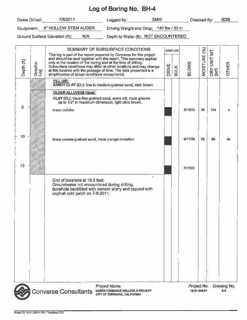
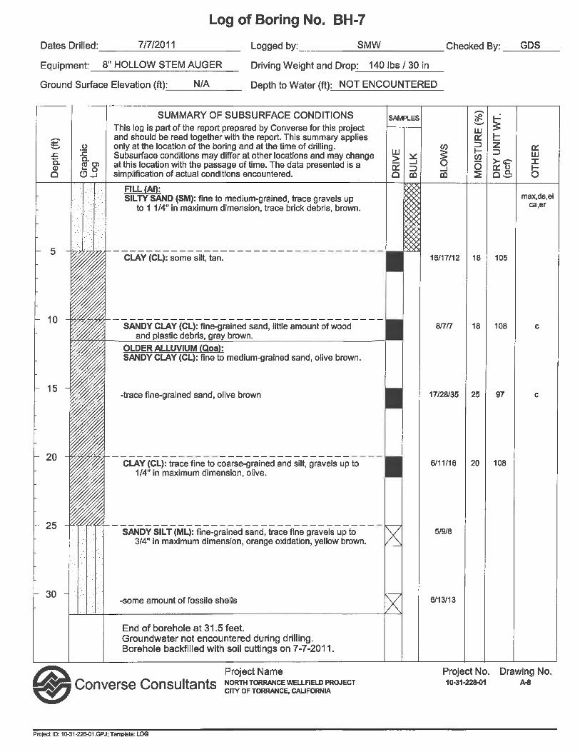
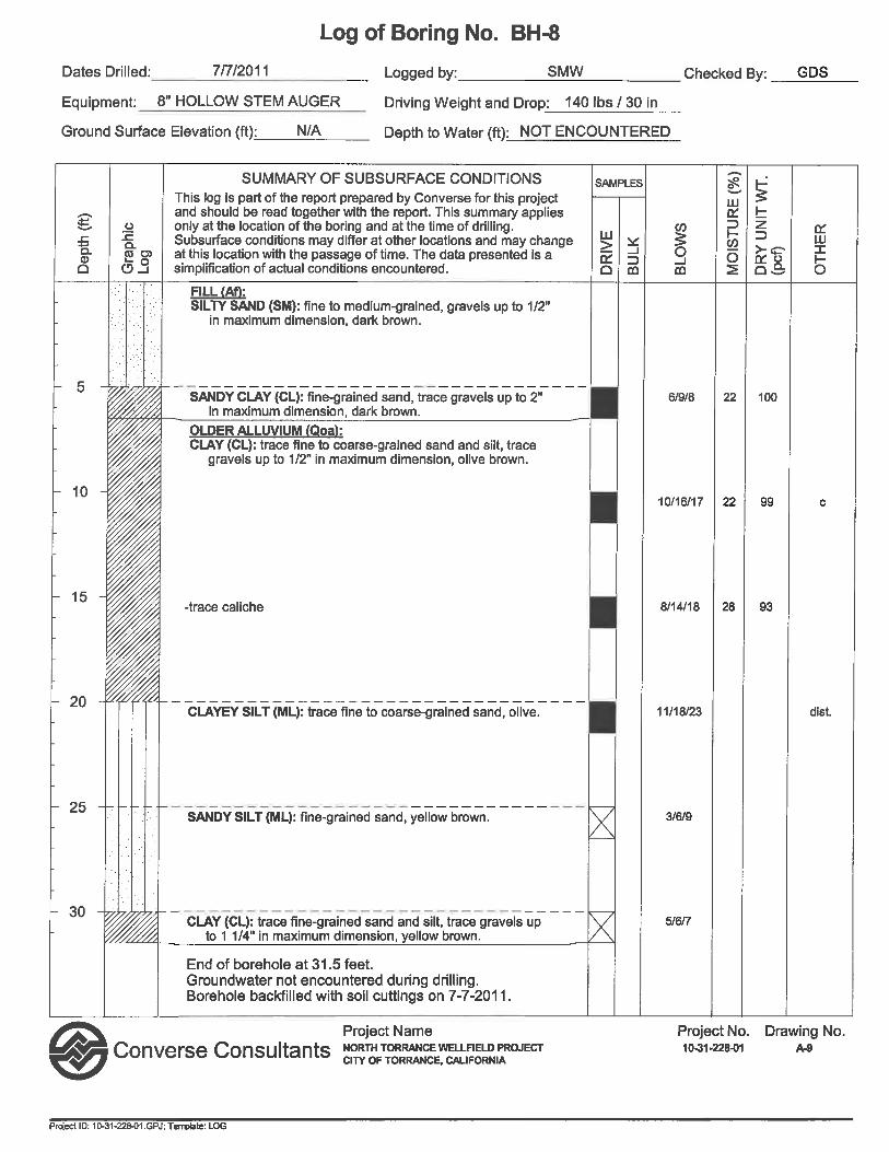
Drawing No. 3, Regional Geologic Map, based on the Geologic Map of the Long Beach 30’ x 60’ Quadrangle (CGS, 2003), has been prepared to show the location of the North Torrance Wellfield Project with respect to the regional geology. 5.2 Geology and Subsurface Profile of Project Site Undocumented fill soils ranging in depth from 2 to 11.5 feet were encountered in the borings drilled within the project areas. The fill consists of primarily clay soils, underlain by older alluvial soils. Native older alluvium generally consists of clay soils. Sampling blow counts for both fill and native soils correlate with firm to stiff conditions. Logs of the subsurface conditions as encountered in the test borings and pump/observation wells were recorded at the time of drilling and are presented on the boring logs included in Appendix A, Field Exploration, along with our field exploration and soil sampling procedures. The following table summarizes the subsurface information gathered along the project alignment: Table No. 2, Summary of Soil Profile at Boring Locations
Boring Locations / (Project Component)
Geologic Profile Descriptions
BH-1, BH-2 and BH-3
(New pipelines to connect existing Well No. 9 and
planned Well No. 11 with the proposed storage tank
site)
Fill: encountered up to 6.5 feet below road surface at BH-2 and BH-3
Clay with Sand (CL)
Older Alluvium: below the roadway pavement at BH-1 and below the fill at BH-2 and BH-3, to the maximum depth explored of 16.5 feet
Clay (CL), Clay with Sand (CL) and Clayey Silt (ML)
BH-4
(Well No. 11)
Fill: encountered up to 2 feet below the ground surface
Sandy Clay (CL)
Older Alluvium: below the fill, to the maximum depth explored of 16.5 feet
Clay (CL)


Geotechnical Study Report North Torrance Wellfield Project
Torrance, California August 11, 2011
Page 6
Converse Consultants
CCMON\JOBFILES\2010\31\228\10-31-228-01_GSR
BH-5
(New drain pipeline)
Fill: encountered up to 3 feet below road surface
Clay with Sand (CL)
Older Alluvium: below the fill, to the maximum depth explored of 16.5 feet
Clay (CL), Clay with Sand (CL) and Clayey Silt with Sand (ML)
BH-6
(Well No. 10)
Fill: encountered up to 2 feet below the ground surface
Sandy Clay (CL)
Older Alluvium: below the fill, to the maximum depth explored of 31.5 feet
Clay (CL) to a depth of 25 feet, Silty Sand (SM) below 25 feet
BH-7 and BH-8
(Three-million-gallon storage tank, and Booster
Pump Station/ Utility building)
Fill: encountered up to 11.5 feet deep at BH-7 and 6.5 feet deep at BH-8
Silty Sand (SM), Clay (CL) and Sandy Clay (CL)
Older Alluvium: below the fill at BH-7 and BH-8, to the maximum depth explored of 31.5 feet
Clay (CL) to depths of 20- 25 feet, Sandy to Clayey Silt (ML) below 20 - 25 feet
5.3 Groundwater Review of readily available water well data from the Los Angeles County Department of Public Works – Ground Water Wells Website (http://gis.dpw.lacounty.gov/wells) indicates groundwater levels at depths of 75 feet or deeper from the ground surface since 1949. Groundwater was not encountered in the borings drilled to the maximum depth explored of 31.5 feet bgs. In general, groundwater levels fluctuate with the seasons and local zones of perched groundwater may be present due to local conditions or during rainy seasons. Groundwater conditions below any given site vary depending on numerous factors including seasonal rainfall, local irrigation, and groundwater pumping, among other factors. Based on our review of available groundwater data, groundwater is not anticipated to be encountered during the planned construction. 5.4 Subsurface Variations Based on results of the subsurface exploration and our experience, variations in the continuity and nature of subsurface conditions within the project site should be anticipated, especially for the undocumented fill soils. Because of the uncertainties involved in the nature and depositional characteristics of the earth material at the site, care should be exercised in interpolating or extrapolating subsurface conditions between or beyond the boring locations. If, during construction, subsurface conditions
Geotechnical Study Report North Torrance Wellfield Project
Torrance, California August 11, 2011
Page 7
Converse Consultants
CCMON\JOBFILES\2010\31\228\10-31-228-01_GSR
differ significantly from those presented in this report, this office should be notified immediately so that recommendations can be modified, if necessary. 6.0 FAULTING AND SEISMIC HAZARDS 6.1 Seismic Setting The subject site is situated within a seismically active region. As is the case for most areas of Southern California, ground-shaking resulting from earthquakes associated with nearby and more distant faults may occur at the project site. During the life of the project, seismic activity associated with active faults can be expected to generate moderate to strong ground shaking at the site. There are a number of nearby fault systems which could produce ground shaking at the site during a major earthquake. The approximate locations of regional capable faults with respect to the project site are shown (excluding blind thrust faults) on Drawing No. 4, Southern California Regional Fault Map. Table No. 3, Summary of Regional Faults, summarizes selected data of known faults capable of seismic activity within 40 kilometers of the site. The data presented on Table No. 3, Summary of Regional Faults, was calculated using UBCSEIS Version 1.03 and EQFAULT Version 3.0 with updated fault data from “The Revised 2002 California Probabilistic Seismic Hazard Maps (Cao et al., 2003)”, Appendix A, and other published geologic data.

Geotechnical Study Report North Torrance Wellfield Project
Torrance, California August 11, 2011
Page 8
Converse Consultants
CCMON\JOBFILES\2010\31\228\10-31-228-01_GSR
Table No. 3, Summary of Regional Faults
Fault Name and Section Approximate *
Distance to Site (kilometers)
Max. Moment Magnitude
(Mmax)
Slip Rate (mm/yr)
Palos Verdes 5.3 7.3 3.00
Newport-Inglewood (L.A. Basin) 7.7 7.1 1.00
Puente Hills Blind Thrust** 20.0 7.1 0.70
Santa Monica 23.8 6.6 1.00
Hollywood 24.6 6.4 1.00
Malibu Coast 25.4 6.7 0.30
Raymond 30.1 6.5 1.50
Elsinore-Whittier 32.3 6.8 2.50
Verdugo/Eagle Rock 33.4 6.9 0.50
Anacapa-Dume 35.4 7.5 3.00
Sierra Madre (Central) 40.6 7.2 2.00
* Distance from the site (1.5 acre parcel) to the surface projection as computed by the computer program UBCSEIS, and per review of published geologic data and mapping. ** Distance from the site to nearest subsurface projection, per data in Appendix A of the 2002 California Fault Parameters Report (Cao et al.,2003). The project site is not located within a currently designated State of California Earthquake Fault Zone (Alquist-Priolo Special Studies Zones) for surface fault rupture. No surface faults are known to project through or towards the site. The closest known faults to the project site with mappable surface expressions are the Palos Verdes fault located approximately 5.3 kilometers to the south and the onshore segments of the Newport Inglewood Fault, located approximately 7.7 kilometers to the east. Palos Verdes Fault The mapped trace of the Palos Verdes Fault is located about 5 kilometers south of the project site along the northern margin of the Palos Verdes Hills. The major component of uplift and tectonic deformation of the Palos Verdes Peninsula is attributed to movement along this fault. The Palos Verdes Fault is considered capable of producing a maximum moment magnitude (Mw) 7.3 earthquake. Newport Inglewood Fault The Newport Inglewood fault zone is located approximately 8 kilometers east of the project site. The Newport Inglewood fault system is about 66 km long on shore and extends
Geotechnical Study Report North Torrance Wellfield Project
Torrance, California August 11, 2011
Page 9
Converse Consultants
CCMON\JOBFILES\2010\31\228\10-31-228-01_GSR
northwest from Huntington Beach through Long Beach to Culver City and the Cheviot Hills. The Newport Inglewood fault continues offshore to the southeast of Huntington Beach and makes landfall in La Jolla as the Rose Canyon fault. The Newport Inglewood fault is characterized by a series of uplifts and anticlines including Newport Mesa, Huntington Beach Mesa, Bolsa Chica Mesa, Alamitos Heights and Landing Hill, Signal Hill and Reservoir Hill, Dominguez Hills and Baldwin Hills. Several earthquakes have occurred along the fault zone including the March 10, 1933 “Long Beach” earthquake of MW 6.4, with its epicenter off Newport Beach, and smaller earthquakes at Inglewood on June 20, 1920 (M 4.9) and May 17, 2009 (M 4.7), Torrance on October 21, 1941 (ML 4.8), Gardena on November 14, 1941 (ML 4.8), and Newport Beach on April 7, 1989 (ML 4.7). The Newport Inglewood fault is considered active and capable of producing a maximum moment magnitude (MW) 7.1 earthquake. The slip rate is approximately 1.0 mm/year but may range up to 2 to 3 mm/year along isolated segments (Cao et al., 2003). Puente Hills Blind Thrust Fault The potential for damage from earthquakes along a zone of north-dipping blind thrust faults in the northern Los Angeles Basin was illustrated by the ML 5.9 Whittier earthquake event on October 1, 1987. Smaller earthquakes experienced north/northeast of downtown Los Angeles on September 3, 1905 (est. M 5.3) and July 16, 1920 (est. M 5.0) are further indications of active faulting in the area. Blind thrust faults are low angle reverse faults which generally have no surface trace. Conventional fault finding trenches, boreholes and paleoseismic dating methods used at the surface have limited use for investigation of these deeply buried thrust fault structures. The geometry and location of the blind thrust fault structures and thrust ramps are based on interpretation of oil well data, seismic and strong motion data solutions, high resolution geophysical data, paleoseismic studies and structural model analyses (Yeats, R.S. 2004; Dolan, J.F. et al., 2003). Examples of blind thrust fault landforms include folding and uplift of areas such as the Elysian, Repetto, Montebello and Puente Hills. The nearest subsurface projection/interpretation of the Puente Hills Blind Thrust Fault is located approximately 20 kilometers east/northeast of the project site (Shaw et al., 2002). The Puente Hills Blind Thrust has been interpreted to include three segments with a combined length of approximately 42 kilometers and a depth range of 3 km to 13 km below ground surface, ramping down toward the east/northeast (Dolan, J.F., et al., 2003). Studies of the Puente Hills Blind Thrust have indicated the occurrence of at least four large (moment-magnitude 7.2 to 7.5) earthquakes for this fault system during the past 11,000 years (Dolan, J.F. et al., 2003).
Geotechnical Study Report North Torrance Wellfield Project
Torrance, California August 11, 2011
Page 10
Converse Consultants
CCMON\JOBFILES\2010\31\228\10-31-228-01_GSR
Seismic hazard fault models for the Los Angeles Basin and vicinity will continue to be refined as new information and technology develops and becomes available through time. 6.2 Seismic History
An analysis of the seismic history of the site was conducted using the computer program EQSEARCH, (Blake, 2000) from the most recent earthquake database available, and attenuation relationships proposed by Boore et al. (1997) for alluvium soil conditions. Based on the analysis of seismic history, the number of earthquakes and aftershocks with a moment magnitude of 5.0 or greater occurring within a distance of 100 kilometers was 140, since the Year 1800. Based on the analysis, the largest earthquake induced ground acceleration affecting the site since the year 1800 was approximately 0.13g, generated from the MW 6.7 Northridge Earthquake in 1994. 6.3 Seismic Hazards As is the case for most areas of Southern California, seismic hazards resulting from earthquakes need to be considered in the design and construction of new projects. In addition to strong ground motion, such hazards include ground rupture, slope instability and liquefaction. As previously reported, the subject site is not located within a State of California Earthquake Fault Zone (formerly Alquist-Priolo Special Studies Zones) for surface fault rupture. The State of California Seismic Hazard Zone Map for the Torrance Quadrangle (March 25, 1999) shows that the project site is not located within an area of potential liquefaction and is not located within a mapped area of potential earthquake-induced landslides due to the relatively flat condition of the site topography. 6.4 Potential Effects of Seismic Activity and Geologic Hazards Other effects of seismic activity (strong ground motion), besides surface fault rupture, soil liquefaction, and landslide, include lateral spreading, earthquake-induced flooding, tsunamis, and seiches. Other geologic hazards to be considered in California include volcanic eruption hazard. Site-specific potential for each of these other seismic and geologic hazards is discussed in the following sections. Surface Fault Rupture: The site is not located within a currently designated State of California Earthquake Fault Zone. Based on a review of existing geologic information, no known active surface fault zone crosses or projects toward the site. The potential for surface rupture resulting from the movement of the nearby major faults is considered remote.

Geotechnical Study Report North Torrance Wellfield Project
Torrance, California August 11, 2011
Page 11
Converse Consultants
CCMON\JOBFILES\2010\31\228\10-31-228-01_GSR
Liquefaction/Seismic Settlement: Liquefaction is defined as the phenomenon where a saturated soil mass exhibits a substantial reduction in its shear strength. This strength reduction is due to the development of excess pore pressure in a saturated soil mass caused by earthquake induced ground motions. Groundwater was not encountered during our subsurface exploration to depths of 31.5 and review of groundwater levels since 1949 indicate the depth to groundwater is greater than 75 feet below existing ground surface. Based on firm to stiff nature of the older alluvial soils encountered at the site, and the deep groundwater level, the potential for liquefaction is very low and dynamic settlement is considered negligible. Lateral Spreading: Seismically induced lateral spreading involves primarily lateral movement of earth materials due to ground shaking. It differs from the slope failure in that complete ground failure involving large movement does not occur due to the relatively smaller gradient of the initial ground surface. Lateral spreading is demonstrated by near-vertical cracks with predominantly horizontal movement of the soil mass involved. The topography at the project site and in the immediate vicinity of the site is relatively flat, with no nearby unsupported slopes or embankments below the site. Under these circumstances, the potential for lateral spreading at the subject site is considered negligible. Earthquake-Induced Flooding: This is flooding caused by failure of dams or other water-retaining structures as a result of earthquakes. The potential of earthquake induced flooding of the subject site is considered to be remote because of regional flood control structures. Tsunamis: Tsunamis are tidal waves generated by fault displacement or major ground movement. Based on the surface elevation and location of the site from the ocean (approximately 3.75 miles west of the site), tsunamis do not pose a hazard. Seiches: Seiches are large waves generated in enclosed bodies of water in response to ground shaking. Based on site location, away from lakes and reservoirs, seiches do not pose a hazard. Volcanic Eruption Hazard: Volcanic eruption hazards are not present at the site or nearby. According to Jennings (1994), the nearest Holocene-epoch volcanic eruption area is the Amboy Crater area located in the Mojave Desert approximately 130 miles east/northeast of the site.

Geotechnical Study Report North Torrance Wellfield Project
Torrance, California August 11, 2011
Page 12
Converse Consultants
CCMON\JOBFILES\2010\31\228\10-31-228-01_GSR
7.0 SEISMIC ANALYSIS 7.1 CBC Seismic Design Parameters
Seismic parameters based on the 2010 California Building Code, calculated with the United States Geological Survey computer program Seismic Hazards Curves, Response Parameters and Design Parameters, Version 5.1.0., and the site coordinates 33.8689 degrees North Latitude, 118.3378 degrees West Longitude are provided on the following table: Table No. 4, CBC Seismic Parameters
Seismic Parameters Site Class D
Mapped Short period (0.2-sec) Spectral Response Acceleration, SS 1.508g
Mapped 1-second Spectral Response Acceleration, S1 0.605g
Site Coefficient, Fa 1.0
Site Coefficient, Fv 1.5
MCE 0.2-sec period Spectral Response Acceleration, SMS 1.508g
MCE 1-second period Spectral Response Acceleration, SM1 0.907g
Design Spectral Response Acceleration for short period, SDS 1.005g
Design Spectral Response Acceleration for 1-second period, SD1 0.605g
7.2 Design Response Spectra A site-specific response spectra was developed for the project for a Maximum Considered Earthquake (MCE) ground motion, defined as a horizontal peak ground acceleration that has a 2 percent probability of being exceeded in 50 years (return period of approximately 2,475 years). In accordance with ASCE 7-05, Section 21.2 and Code Application Notice (CAN 2-1802A.6.2) the site-specific response spectra can be taken as the lesser of the probabilistic maximum rotated component of MCE ground motion and the 84th percentile of deterministic maximum rotated component of MCE ground motion response spectra. The design response spectra can be taken as 2/3 of the site-specific MCE response spectra, but should not be lower than 80 percent of CBC general response spectra. A site specific response analysis, using available fault data within 100 kilometers of the site, was developed using the computer program EZ-FRISK by Risk Engineering (v. 7.62) and the 2008 USGS Statewide Fault Model. Attenuation relationships proposed by Boore and Atkinson (2008), Campbell and Bozorgnia (2008), Chiou and Youngs (2008) were used in the analysis. These attenuation relationships are based on Next
Geotechnical Study Report North Torrance Wellfield Project
Torrance, California August 11, 2011
Page 13
Converse Consultants
CCMON\JOBFILES\2010\31\228\10-31-228-01_GSR
Generation Attenuation (NGA) project model. An average shear wave velocity for the upper 30 meters of soil profile (Vs30) of 270 meters per second was used, based upon our site-specific exploration. Shear wave velocities of 1,000 meters per second at 150 meters below grade, and 2,500 meters per second at 3,000 meters below grade were also selected for our EZ-Frisk Analysis. Maximum rotated components were determined using Huang (2008) method. Applicable response spectra data are presented in a Table below and on Drawing No. 5, Site-Specific Design Response Spectra. These curves correspond to response values obtained from above attenuation relations for horizontal elastic single-degree-of-freedom systems with equivalent viscous damping of 5 percent of critical damping. Table No. 5, Site-Specific Design Response Spectra Data
Period (sec)
Maximum Rotated
Probabilistic MCE
Spectra, (g)
84th Percentile of
Maximum Rotated
Deterministic MCE
Response Spectra, (g)
Deterministic CBC
Lower Level, (g)
Site Specific MCE, (g)
Design Response Spectra, (5% of
Damping ) (g)
General Response
Spectra Lower Limit, (g)
0.03 0.786 0.881 1.50 0.786 0.524 0.442
0.05 0.891 0.979 1.50 0.891 0.594 0.522
0.10 1.232 1.289 1.50 1.232 0.821 0.723
0.20 1.579 1.668 1.50 1.579 1.053 0.804
0.30 1.734 1.800 1.50 1.734 1.156 0.804
0.40 1.641 1.805 1.50 1.641 1.094 0.804
0.50 1.550 1.755 1.50 1.550 1.033 0.804
0.75 1.278 1.511 1.50 1.278 0.852 0.645
1.00 1.052 1.224 0.90 1.052 0.701 0.484
2.00 0.620 0.965 0.45 0.620 0.413 0.242
3.00 0.433 0.832 0.30 0.433 0.288 0.161
4.00 0.335 0.733 0.23 0.335 0.223 0.121
Vertical acceleration at the site may be calculated in accordance with ASCE 7-05, Section 12.4. The site-specific design response parameters are provided in the following table. These parameters were determined from Design Response Spectra presented in the table above, and following guidelines of ASCE Section 21.4.

Geotechnical Study Report North Torrance Wellfield Project
Torrance, California August 11, 2011
Page 14
Converse Consultants
CCMON\JOBFILES\2010\31\228\10-31-228-01_GSR
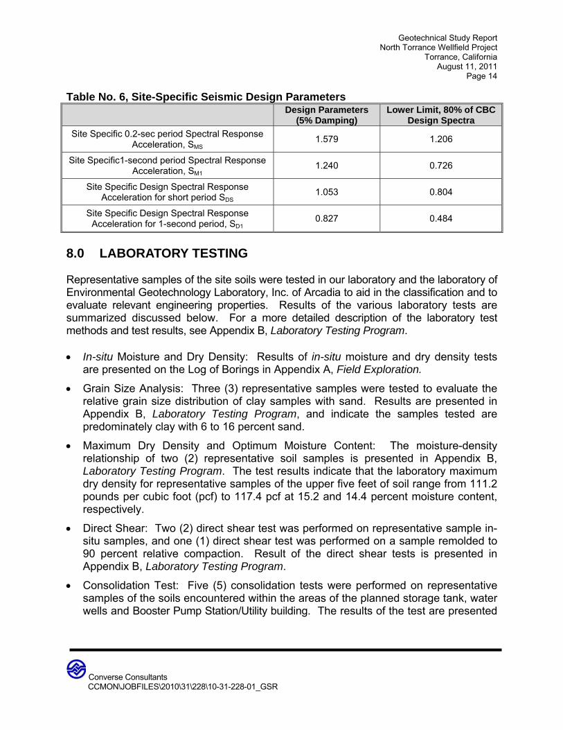
Table No. 6, Site-Specific Seismic Design Parameters Design Parameters
(5% Damping) Lower Limit, 80% of CBC
Design Spectra
Site Specific 0.2-sec period Spectral Response Acceleration, SMS
1.579 1.206
Site Specific1-second period Spectral Response Acceleration, SM1
1.240 0.726
Site Specific Design Spectral Response Acceleration for short period SDS
1.053 0.804
Site Specific Design Spectral Response Acceleration for 1-second period, SD1
0.827 0.484
8.0 LABORATORY TESTING Representative samples of the site soils were tested in our laboratory and the laboratory of Environmental Geotechnology Laboratory, Inc. of Arcadia to aid in the classification and to evaluate relevant engineering properties. Results of the various laboratory tests are summarized discussed below. For a more detailed description of the laboratory test methods and test results, see Appendix B, Laboratory Testing Program. In-situ Moisture and Dry Density: Results of in-situ moisture and dry density tests
are presented on the Log of Borings in Appendix A, Field Exploration.
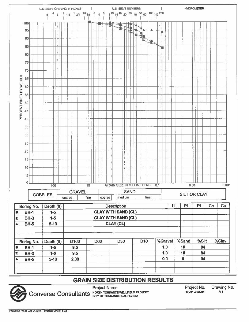
Grain Size Analysis: Three (3) representative samples were tested to evaluate the relative grain size distribution of clay samples with sand. Results are presented in Appendix B, Laboratory Testing Program, and indicate the samples tested are predominately clay with 6 to 16 percent sand.
Maximum Dry Density and Optimum Moisture Content: The moisture-density relationship of two (2) representative soil samples is presented in Appendix B, Laboratory Testing Program. The test results indicate that the laboratory maximum dry density for representative samples of the upper five feet of soil range from 111.2 pounds per cubic foot (pcf) to 117.4 pcf at 15.2 and 14.4 percent moisture content, respectively.
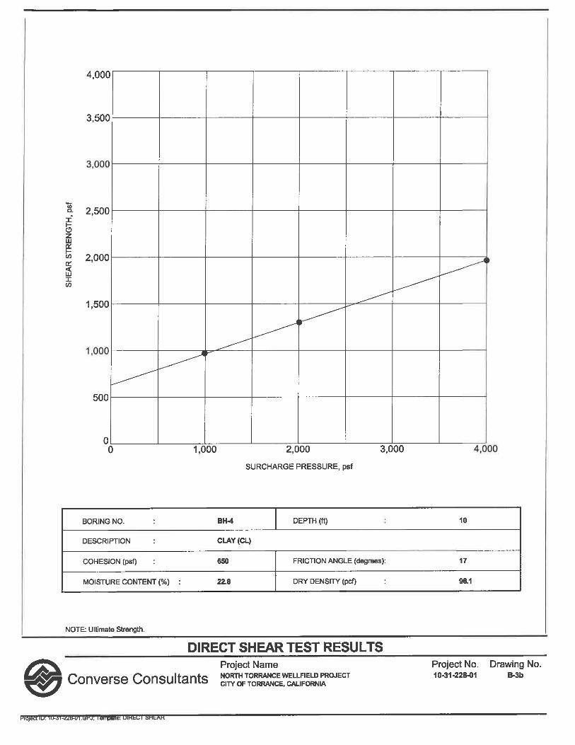
Direct Shear: Two (2) direct shear test was performed on representative sample in-situ samples, and one (1) direct shear test was performed on a sample remolded to 90 percent relative compaction. Result of the direct shear tests is presented in Appendix B, Laboratory Testing Program.
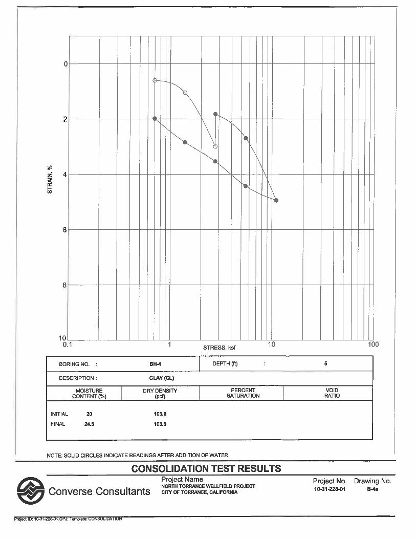
Consolidation Test: Five (5) consolidation tests were performed on representative samples of the soils encountered within the areas of the planned storage tank, water wells and Booster Pump Station/Utility building. The results of the test are presented

Geotechnical Study Report North Torrance Wellfield Project
Torrance, California August 11, 2011
Page 15
Converse Consultants
CCMON\JOBFILES\2010\31\228\10-31-228-01_GSR
in Appendix B, Laboratory Testing Program. Based on the results of these tests, the compressibility of the site native soils is considered moderate.
Expansion Index: Two (2) representative samples of the site soils (one sand and one clay) were tested to evaluate Expansion Index (EI). Test results are included in Appendix B, Laboratory Testing Program. The test results indicate that the native clay site soils have a medium expansion potential (EI 51 to 90) and the sandy fill soils in the vicinity of BH-7 have a very low expansion potential (EI 0 to 20).
Soil Corrosivity: Two (2) representative samples of the site soils were tested to evaluate soil corrosivity with respect to common construction materials such as concrete and steel. The test results are presented in Appendix B, Laboratory Testing Program. Test results are also discussed in Section 12.8, Soil Corrosivity Evaluation.
R-Value: Two (2) representative bulk soil samples were tested for resistance value (R-value) in accordance with State of California Standard Method 301-G. This test is designed to provide a relative measure of soil strength for use in pavement design. The test results are presented in Appendix B, Laboratory Testing Program.
For additional information on the subsurface conditions, see the Logs of Borings in Appendix A, Field Exploration. 9.0 GEOTECHNICAL EVALUATION AND CONCLUSIONS Based on the results of our background review, subsurface exploration, laboratory testing, geotechnical analyses, and understanding of the planned construction, the project site consists of the following geotechnical conditions:
Relatively shallow depths of undocumented fill soils (clay) over firm older alluvial soils (clay) in the areas of planned water pipelines, well sites, and drain pipelines.
Undocumented fill soils (silty sand) ranging from approximately 6.5 to 11.5 feet deep in the areas of the planned storage tank and booster pump/utility building. Based on our laboratory test results, the undocumented fill soils are compressible and require mitigation for foundation and slab support. The fill soils are underlain by firm older alluvial soils.
Onsite clayey soils have a “medium” expansive potential, and require mitigation for foundation and slab support.
Due to compressible undocumented fill and expansive soils conditions, we recommend the planned areas of the wells, storage tank and booster pump/utility building be supported on compacted fill soils achieved through over-excavation and re-compaction. Depths of grading for remedial earthwork are anticipated to be 2 feet for the well locations. Over-
Geotechnical Study Report North Torrance Wellfield Project
Torrance, California August 11, 2011
Page 16
Converse Consultants
CCMON\JOBFILES\2010\31\228\10-31-228-01_GSR
excavation for reservoir should be at least 8 feet below existing grade, or to the depth of fill, whichever is deeper. Over-excavation for building should be at least 12 feet below existing grade, or to the depth of fill, whichever is deeper. Over-excavation for pipelines is not needed. Based on our understanding of the project, trenchless techniques may be utilized for installation of the drain pipeline planned below the Caltrans right-of-way (Interstate 405). The results of our subsurface exploration indicate relatively firm clay soils and a deep groundwater condition for this area. Therefore, it is our opinion that trenchless construction for the drain pipeline can be accomplished by an experienced contractor using pipe jacking/micro-tunneling equipment. 10.0 EARTHWORK AND SITE GRADING RECOMMENDATIONS Based on our field exploration, laboratory testing, and analyses of subsurface conditions at the site, remedial grading will be required to prepare the planned areas of the wells, storage tank and booster pump/utility building for slab and foundation support. Vertical excavations greater than 5 feet at the site will require either shoring or sloped excavation. To reduce differential settlement of future at-grade improvements, the variations in the soil type, degree of compaction, and thickness of the compacted fill placed underneath future improvements should be kept uniform. Site grading recommendations provided below are based on our experience with similar projects in the area and our evaluation of this study. 10.1 Excavatability Based on our field exploration, the site soils should be excavatable with conventional heavy-duty earth-moving and trenching equipments. Temporary sloped excavation is feasible if performed in accordance with the slope ratios provided in Section 12.2, Temporary Excavations. If temporary sloped excavation is not feasible due to space limitations, temporary shoring is required. Existing utilities should be accurately located and either protected or removed as required. 10.2 Over-excavation/Removal Existing soils below planned wells should be over-excavated to a depth of approximately 2 feet, moisture-conditioned if needed, and replaced as compacted fill. The remedial grading should extend at least 2 feet beyond the well foundation slab. Due to compressible undocumented fill and expansive soils conditions, we recommend the planned areas of the wells, storage tank and booster pump/utility building be supported on compacted fill soils achieved through over-excavation and re-compaction.

Geotechnical Study Report North Torrance Wellfield Project
Torrance, California August 11, 2011
Page 17
Converse Consultants
CCMON\JOBFILES\2010\31\228\10-31-228-01_GSR
Depths of grading for remedial earthwork are anticipated to be 2 feet for the well locations. Over-excavation for reservoir should be at least 8 feet below existing grade, or to the depth of fill, whichever is deeper. Over-excavation for building should be at least 12 feet below existing grade, or to the depth of fill, whichever is deeper. The extent and depth of over-excavation shall be verified and approved by a geotechnical consultant during grading operations. The remedial grading should extend laterally to a distance equal to the depth of removal, or at least 5 feet beyond the foundation/slab, whichever is greater. Over-excavation for pipelines is not needed. For new pavement areas we recommend an over-excavation of at least two (2) feet below existing grades. The remedial grading should extent horizontally a distance equal to the depth of over-excavation. 10.3 Structural Fill The bottom of the excavations should be scarified to a depth of at least six (6) inches and compacted to at least 90 percent of relative compaction, to establish a firm and unyielding surface for receiving compacted structural fill. Prior to compaction, fill materials should be thoroughly mixed and moisture conditioned within two (2) percent of optimum moisture content for granular soils or at about three (3) percent above optimum moisture content for fine-grained soils. Excavated site soils, free of deleterious materials and rocks greater than three (3) inches in the largest dimension, are suitable for placement as compacted fill. Any import fill should be tested and approved by a geotechnical consultant. All import fill should have an expansion potential less than 20. To mitigate the expansive soils, we recommend at least 24 inches thick crushed aggregate base (CAB), i.e. Caltrans Class 2 aggregate base, be placed beneath reservoir foundations and slab. For pump station/utility building, at least 24 inches thick sandy soils (EI less than 20) or CAB shall be placed beneath foundations and slab. All fill, if not specified otherwise elsewhere in this report, should be compacted to at least 90 percent of the laboratory dry density in accordance with the ASTM Standard D1557 test method. Crushed aggregate base beneath foundation and slab and the upper twelve (12) inches of fill underlying pavements should be compacted to at least 95 percent of the laboratory maximum dry density. Moisture conditioning of excavated soils may be necessary prior to the material being placed as compacted fill. The amount of processing required for proper moisture conditioning at the site will depend on the seasonal variations in the in-situ moisture conditions, the depth of cut, the equipment, and the processing method.

Geotechnical Study Report North Torrance Wellfield Project
Torrance, California August 11, 2011
Page 18
Converse Consultants
CCMON\JOBFILES\2010\31\228\10-31-228-01_GSR
10.4 Subterranean Structure Wall Backfill Compaction of backfill adjacent to structural walls can produce excessive lateral pressures. Improper types and locations of compaction equipment and/or compaction techniques may damage the walls. The use of heavy compaction equipment should not be permitted within a horizontal distance of five (5) feet from the wall. Backfill behind any structural walls within the recommended 5-foot zone should be compacted using lightweight construction equipment such as handheld compactors to avoid overstressing the walls. Excavated site soils, free of deleterious materials and rocks larger than three (3) inches in the largest dimension should be suitable for placement as compacted backfill. Care should be taken to avoid placing expansive, on-site fine-grained material within three (3) feet of structural walls. Any import fill should be tested for soil classification and expansion index (less than 20) and approved by a geotechnical consultant prior to delivery to the site. As an alternative to compacted fill, Controlled Low-Strength Material (CLSM) can be used for backfill. CLSM is a low strength- and high slump- self compacted, cementitious material used primarily as backfill in lieu of compacted fill. CLSM shall be a mixture of Portland cement, fly ash or other approved materials, aggregates, water and admixtures proportioned to provide a non-segregating, self-consolidating, free-flowing and excavatable material, which will result in a hardened, dense, non-settling fill. CLSM used for backfill should have a cast density of 120 pcf minimum and a compressive strength at 28 days of 200 psi minimum and proportion to be a flowable, non-segregating, self-consolidating low shrink slurry. 10.5 Pipe Backfill Recommendations It is anticipated that the natural soils will provide a firm foundation for planned water pipelines and drain pipelines. Any soft and/or unsuitable material encountered at the pipe invert should be removed and replaced with an adequate bedding material. 10.5.1 Pipe Subgrade Preparation The pipe subgrade should be level, firm, uniform, free of loose materials and properly graded to provide uniform bearing and support to the entire section of the pipe placed on bedding material. Subgrade soil surfaces for pipeline should be scarified to a depth of at least six (6) inches and be compacted to a minimum of 90 percent relative compaction. Protruding oversize particles larger than two (2) inches in the largest dimension, if any, should be removed from the trench bottom and replaced with compacted materials. If yielding soft subgrade is encountered, we recommend over-excavate at least 18 inches, place geofabric (Mirafi HP570 or equivalent) at bottom of

Geotechnical Study Report North Torrance Wellfield Project
Torrance, California August 11, 2011
Page 19
Converse Consultants
CCMON\JOBFILES\2010\31\228\10-31-228-01_GSR
excavation to receive 18 inches compacted base materials (CMB or equivalent). Base material should be compacted to at least 90 percent of relative compaction. During the digging of depressions for proper sealing of the pipe joints, the pipe should rest on a prepared bottom for as near its full length as is practicable. 10.5.2 Pipe Bedding Bedding is defined as the material supporting and surrounding the pipe to 12 inches above the pipe. To provide uniform and firm support for the pipe, compacted granular materials such as clean sand, gravel or ¾-inch crushed aggregate or crushed rock may be used as pipe bedding material. The type and thickness of the granular bedding placed underneath and around the pipe, if any, should be selected by the pipe designer. The load on the rigid pipes and deflection of flexible pipes and, hence, the pipe design, depends on the type and the amount of bedding placed underneath and around the pipe. Care should be taken to densify the bedding material below the springline of the pipe. Pipe design generally requires a granular material with a sand equivalent (SE) greater than 30. Bedding material for the pipes should be free from oversized particles (greater than 1-inch). Therefore, on-site native materials and undocumented fill soils are not suitable to be used for pipe bedding. Migration of fines from the surrounding native and/or fill soils must be considered in selecting the gradation of any imported bedding material. We recommend that the pipe bedding material should satisfy the following criteria:
D15 < 2.5 mm and D50 < 19.0 mm
Where D15 and D50 represent particle sizes of the bedding material corresponding to 15 percent and 50 percent passing by weight, respectively. 10.5.3 Trench Zone Backfill The trench zone is defined as the portion of the trench above the pipe bedding extending up to the final grade level of the trench surface. The following specifications are recommended to provide a basis for quality control during the placement of trench backfill. Trench excavations to receive backfill shall be free of trash, debris or other unsatisfactory materials at the time of backfill placement. Excavated on-site soils free of oversize particles, defined as larger than one (1) inch in maximum dimension in the
Geotechnical Study Report North Torrance Wellfield Project
Torrance, California August 11, 2011
Page 20
Converse Consultants
CCMON\JOBFILES\2010\31\228\10-31-228-01_GSR
upper 12 inches of subgrade soils and larger than three (3) inches in the largest dimension in the trench backfill below, and deleterious matter after proper processing may be used to backfill the trench zone. Imported trench backfill, if used, should be approved by the project geotechnical consultant prior to delivery at the site. Trench backfill shall be compacted to 90 percent of the laboratory maximum dry density as per ASTM Standard D1557 test method. At least the upper twelve (12) inches of trench underlying pavements should be compacted to at least 95 percent of the laboratory maximum dry density. Trench backfill shall be compacted by mechanical methods, such as sheepsfoot, vibrating or pneumatic rollers, or mechanical tampers, to achieve the density specified herein. The thickness of soil lifts/layers prior to compaction should not exceed eight (8) inches. Each layer shall be evenly spread, moistened or dried as necessary, and then tamped or rolled until the specified density has been achieved. As an alternative to compacted fill for trench backfill, controlled low-strength material may be used. Please refer to report section 10.4 for specifications. The contractor shall select the equipment and processes to be used to achieve the specified density without damage to adjacent ground and completed work. The field density of the compacted soil shall be measured by the ASTM Standard D1556 or ASTM Standard D2922 test methods or equivalent. Observation and field tests should be performed by Geotechnical Consultant during construction to confirm that the required degree of compaction has been obtained. Where compaction is less than that specified, additional effort shall be made with adjustment of the moisture content as necessary, until the specified compaction is obtained. It should be the responsibility of the contractor to maintain safe conditions during cut and/or fill operations. Trench backfill shall not be placed, spread or rolled during unfavorable weather conditions. When the work is interrupted by heavy rain, fill operations shall not be resumed until field tests by the project's geotechnical consultant indicate that the moisture content and density of the fill are as previously specified. 10.5.4 Flexible Pipe Joints We recommend flexible joints should be installed to compensate possible differential settlements where the buried pipes interface with structures and for joints between the structures. 10.6 Expansive Soil Mitigation The native soils at the site have a “medium” expansion potential. The onsite soil materials will be mixed during the grading and the expansion potential might change. Therefore, the

Geotechnical Study Report North Torrance Wellfield Project
Torrance, California August 11, 2011
Page 21
Converse Consultants
CCMON\JOBFILES\2010\31\228\10-31-228-01_GSR
expansion potential of site soils should be verified after the grading. Slabs, foundations and pavement placed directly on expansive subgrade soil will likely crack over time. The soil materials with expansion index higher than 20 should be mitigated. We recommend at least 24 inches thick crushed aggregate base (CAB), i.e. Caltrans Class 2 aggregate base, shall be placed beneath foundations and slab-on-grade to mitigate the expansive soils. 10.7 Shrinkage and Subsidence For the remedial grading, the shrinkage and/or bulking of soils will depend on, among other factors, the depth of cut and/or fill, and the grading method and equipment utilized. For preliminary estimation, utilizing our current exploration information, bulking and shrinkage factors for various units of earth material at the site may be taken as presented below: The approximate shrinkage factor for native and undocumented fill soils is estimated
to range from ten (10) to fifteen (15) percent.
Subsidence would depend on the construction methods including type of equipment utilized. For estimation purposes, ground subsidence may be taken as 0.15 feet.
Although these values are only approximate, they represent our best estimates of the factors to be used to calculate lost volume that may occur during grading. If more accurate shrinkage and subsidence factors are needed, it is recommended that field-testing using the actual equipment and grading techniques be conducted. 10.8 Site Drainage Adequate positive drainage should be provided away from building pad/excavation areas to prevent ponding and to reduce percolation of water into the foundation soils. Building pads should have a drainage gradient of at least two (2) percent towards drainage facilities. A desirable drainage gradient is one (1) percent for paved areas and two (2) percent in landscaped areas. Surface drainage should be directed to suitable non-erosive devices. Slope drainage should be constructed in accordance with the California Building Code (2010).
Geotechnical Study Report North Torrance Wellfield Project
Torrance, California August 11, 2011
Page 22
Converse Consultants
CCMON\JOBFILES\2010\31\228\10-31-228-01_GSR
11.0 DESIGN RECOMMENDATIONS The proposed well slabs, storage tank and booster pump/utility building should be supported on compacted fill soils. The subject site is located within an area underlain by variable depths of undocumented fill soils. 11.1 Shallow Foundation Design The well slabs, storage tank and booster pump/utility building can be supported on slabs and shallow footings bearing on future compacted fill provided the following recommendations incorporated into design and construction. 11.1.1 Vertical Capacity Footings should be founded at least 18 inches below lowest adjacent final grade on compacted fill. Footings should be at least 12 inches wide for continuous footings and 24 inches wide for isolated footings. The allowable dead plus live load bearing value is 2,000 psf for footings supported on 24-inch-thick compacted soil fill, and 3,000 psf for footings supported on 24-inch-thick compacted CAB. The allowable bearing pressure can be increased by 600 psf for each additional foot of excavation depth and by 300 psf for each additional foot of excavation width up to a maximum value of 4,500 psf. The net allowable bearing values indicated above are for the dead loads and frequently applied live loads and are obtained by applying a factor of safety of 3.0 to the net ultimate bearing capacity. 11.1.2 Lateral Capacity Resistance to lateral loads can be provided by friction acting at the base of the foundation and by passive earth pressure. A coefficient of friction of 0.3 may be assumed with normal dead load forces. An allowable passive earth pressure of 300 psf per foot of depth up to a maximum of 3,000 psf may be used for footings poured against compacted fill or native soil. The values of coefficient of friction and allowable passive earth pressure include a factor of safety of 1.5. 11.1.3 Settlement The static settlement of structures supported on continuous and/or spread footings founded on competent native soils will depend on the actual footing dimensions and the imposed vertical loads. Most of the footing settlement at the project site is expected to occur immediately after the application of the load. Based on the maximum allowable net bearing pressures presented above, static settlement is anticipated to be less than
Geotechnical Study Report North Torrance Wellfield Project
Torrance, California August 11, 2011
Page 23
Converse Consultants
CCMON\JOBFILES\2010\31\228\10-31-228-01_GSR
0.75 inch. Differential settlement is not expected to exceed one-half of the total settlement over a 50-foot span. 11.1.4 Dynamic Increases Bearing values indicated above are for total dead load and frequently applied live loads. The above vertical bearing may be increased by 33% for short durations of loading which will include the effect of wind or seismic forces. The allowable passive pressure may be increased by 33% for lateral loading due to wind or seismic forces. 11.2 Slabs-on-grade The design of the slab-on-grade will depend on, among other factors, the expansion potential of the pad soils. Based on the expansion index test performed during this evaluation, the expansion potential of the native site soils at a shallow depth is medium (EI 51 to 90). Slabs-on-grade supported directly on expansive soils should be designed accordingly. Mitigation of expansive soil is recommended in Section 10.6. Slabs-on-grade should be supported on properly compacted fill. Compacted fill used to support slabs-on-grade should be placed and compacted in accordance with report section 10.0 Recommendations – Earthwork and Site Grading, and the general recommendations given in Appendix C, Earthwork Specifications. Slabs-on-grade should have a minimum thickness of four (4) inches nominal for support of normal ground-floor live loads. Minimum reinforcement for slabs-on-grade should be No. 4 reinforcing bars, spaced at 24 inches on-center each way. The thickness and reinforcement of more heavily-loaded slabs will be dependent upon the anticipated loads and should be designed by a structural engineer. A static modulus of subgrade reaction equal to 150 pounds per square inch per inch may be used in structural design of concrete slabs-on-grade. It is critical that the exposed subgrade soils should not be allowed to desiccate prior to the slab pour. Care should be taken during concrete placement to avoid slab curling. Slabs should be designed and constructed as promulgated by the ACI and Portland Cement Association (PCA). Prior to the slab pour, all utility trenches should be properly backfilled and compacted. 11.3 Modulus of Subgrade Reaction Design of the structures supported on subgrade prepared in accordance with the recommendations provided in this report may be based on a soil modulus of subgrade reaction of (ks) of 150 pounds per square inch per inch.

Geotechnical Study Report North Torrance Wellfield Project
Torrance, California August 11, 2011
Page 24
Converse Consultants
CCMON\JOBFILES\2010\31\228\10-31-228-01_GSR
11.4 Retaining Wall Design The following recommendations should be followed in the design and construction for any planned retaining structures. The earth pressure behind any buried wall depends primarily on the allowable wall movement, type of backfill materials, backfill slopes, wall inclination, surcharges, and any hydrostatic pressure. The following equivalent fluid pressures are recommended for vertical walls with no surcharge, and level backfill. Table No. 7, Earth Pressures for Retaining Wall Design
Retaining Wall Types Earth Pressure (Equivalent Fluid pressure)
Cantilever Wall (Active pressure) 45 pcf (triangular distribution)
Restrained Wall (At-rest pressure) 60 pcf (triangular distribution)
The recommended lateral pressures assume that the walls are fully back-drained to prevent build-up of hydrostatic pressure. Adequate drainage could be provided by means of permeable drainage materials wrapped in filter fabric installed behind the walls. The drainage system should consist of perforated pipe surrounded by one cubic foot of free draining, uniformly graded, ¾ -inch washed, crushed aggregate, and wrapped in filter fabric such as Mirafi 140N or equivalent, placed at bottom of wall. The filter fabric should overlap approximately 12 inches or more at the joints. The subdrain pipe should consist of perforated, four-inch diameter, rigid ABS (SDR-35) or PVC A-2000, or equivalent, with perforations placed down. Alternatively, a prefabricated drainage composite system such as the Miradrain G100N or equivalent can be used. The subdrain should be connected to a sump pump. Design recommendations presented above are based on the assumption that retaining walls will retain either on-site soils or imported non-expansive soils that have been properly compacted. All backfill should be compacted to at least 90 percent relative compaction, with the comparative maximum density evaluated through laboratory testing in accordance with ASTM D 1557. Large equipment surcharge adjacent to newly constructed concrete walls should be avoided until the curing concrete reaches design strength. Backfill operations should be performed as specified in report section 10. Surcharge pressures from other on-grade structures should be added to the above earth pressures for surcharges within a horizontal distance less than or equal to the wall height. Surcharge coefficients of 45% of any uniform vertical surcharge should be added as a horizontal wall pressure for walls retaining level backfill.

Geotechnical Study Report North Torrance Wellfield Project
Torrance, California August 11, 2011
Page 25
Converse Consultants
CCMON\JOBFILES\2010\31\228\10-31-228-01_GSR
11.5 Structural Pavement Recommendations
The flexible pavement structural section design recommendations were performed using R-value of 5 for the subgrade soil in accordance with the CALTRANS Highway Design Manual, Chapter 630 without a factor of safety. No specific traffic study was performed to determine the Traffic Index (TI) for the proposed project. Pavement sections are provided for the Traffic Indices (TIs) ranging from 4 to 9. The recommended flexible pavement structural sections for various TI conditions are presented in the following table:
Table No. 8, Flexible Pavement Structural Sections
Design R-value Design TI
Asphalt Concrete (AC) Over Aggregate Base (AB) Structural Sections
Full AC Structural Section
AC (inches) AB (inches) AC (inches)
5
4 3 6.0 5.5
5 4 7.5 7.0
6 5 9.5 9.0
7 6 11.5 10.5
8 7 13.5 12.0
9 8 15.0 13.5
Actual traffic index and traffic load should be determined by either Civil Engineer or Traffic Engineer. The above pavement sections are recommended as a guideline for basic usage of the indicated TI values, and may not be sufficient for actual traffic loading. Base material shall conform to requirements for a Class 2 Aggregate Base (AB) or equivalent (such as crushed miscellaneous base - CMB) and should be placed in accordance with the requirements of the Standard Specifications for Public Works Construction (SSPWC, latest Edition). Asphaltic materials should conform to Section 203-1, "Paving Asphalt," of the Standard Specifications for Public Works Construction (SSPWC, latest Edition) and should be placed in accordance with Section 302-5, "Asphalt Concrete Pavement," of the SSPWC, 2009 edition. 11.6 Soil Corrosivity Evaluation Converse retained the services of Environmental Geotechnical Laboratory, Inc., located in Arcadia, California, to test two (2) bulk soil samples taken in the general area of the

Geotechnical Study Report North Torrance Wellfield Project
Torrance, California August 11, 2011
Page 26
Converse Consultants
CCMON\JOBFILES\2010\31\228\10-31-228-01_GSR
proposed improvements. The tests included minimum resistivity, pH, soluble sulfates, and chloride content, with the results summarized on the following table: Table No. 9, Corrosivity Test Results
Boring No. Sample Depth (feet)
pH (Caltrans 643)
Soluble Chlorides
(Caltrans 422) ppm
Soluble Sulfate
(Caltrans 417) ppm
Saturated Resistivity
(Caltrans 643) Ohm-cm
BH-1 1-5 8.30 105 360 970
BH-7 0-5 7.48 230 10 1,500
The pH value and chloride content of soil samples tested are in the non-corrosive range to ferrous metal. The saturated resistivity is in the potentially corrosive range to ferrous metal. The soluble sulfate concentrations tested are in the non-corrosive range to concrete according to the California Department of Transportation Corrosion Guidelines, dated September 2003. If imported soils are used during construction, additional testing and evaluation of the as-graded soils is recommended. A corrosion engineer may be consulted for appropriate mitigation procedures and construction design, if needed. Conventional corrosion mitigation measures may include the following: Steel and wire concrete reinforcement should have at least three inches of concrete
cover where cast against soil, unformed. Below-grade ferrous metals should be given a high-quality protective coating, such
as 18-mil plastic tape, extruded polyethylene, coal-tar enamel, or Portland cement mortar.
Below-grade metals should be electrically insulated (isolated) from above-grade
metals by means of dielectric fittings in ferrous utilities and/or exposed metal structures breaking grade.
11.7 Site Drainage Adequate positive drainage should be provided away from the structures to prevent ponding and to reduce percolation of water into structural backfill. A desirable slope for surface drainage is two (2) percent in landscaped areas and one (1) percent in paved areas. Planters and landscaped areas adjacent to the building perimeter should be designed to minimize water infiltration into the subgrade soils. Gutters and downspouts should be
Geotechnical Study Report North Torrance Wellfield Project
Torrance, California August 11, 2011
Page 27
Converse Consultants
CCMON\JOBFILES\2010\31\228\10-31-228-01_GSR
installed on the roof, and runoff should be directed to the storm drain through non-erosive devices. Lower level walkways and open patio areas may require special drainage provisions and sump pumps to provide suitable drainage. 11.8 Soil Parameters for Pipe Design Structural design of pipeline requires proper evaluation of all possible loads acting on the walls, including dead and live or transient loads. The stresses and strains induced on the walls depend on many factors, including the type of soil density, bearing pressure, angle of internal friction, coefficient of passive earth pressure, and coefficient of friction at the interface between the backfill and native soils. The recommended values of the various soil parameters for the pipe design are provided below: Average compacted fill unit weigh =125 pcf
Angle of internal friction of soils = 30º
Soil cohesion c = 0 psf
Coefficient of friction between backfill and native soils fs = 0.30
Bearing pressure against alluvial soils or compacted fill 1,500 psf
Coefficient of passive earth pressure Kp = 3.0 11.9 Bearing Pressure for Anchor and Thrust Blocks Allowable net bearing pressure of 1,500 pounds per square foot may be used for anchor and thrust block design against existing fill and alluvium. Such thrust blocks should be at least 24 inches wide. Resistance to lateral forces can be assumed provided by friction at the base of thrust blocks and by passive earth pressure. Frictional and passive resistance can be combined for the design of anchors and thrust blocks. An ultimate value of coefficient of friction of 0.3 may be used between the thrust block and the supporting natural soil or compacted fill. A passive earth pressure of 300 psf per foot of depth may be used for the sides of thrust blocks or anchors poured against undisturbed or compacted fill. The value of the passive lateral earth pressure should be limited to 1,500 psf.
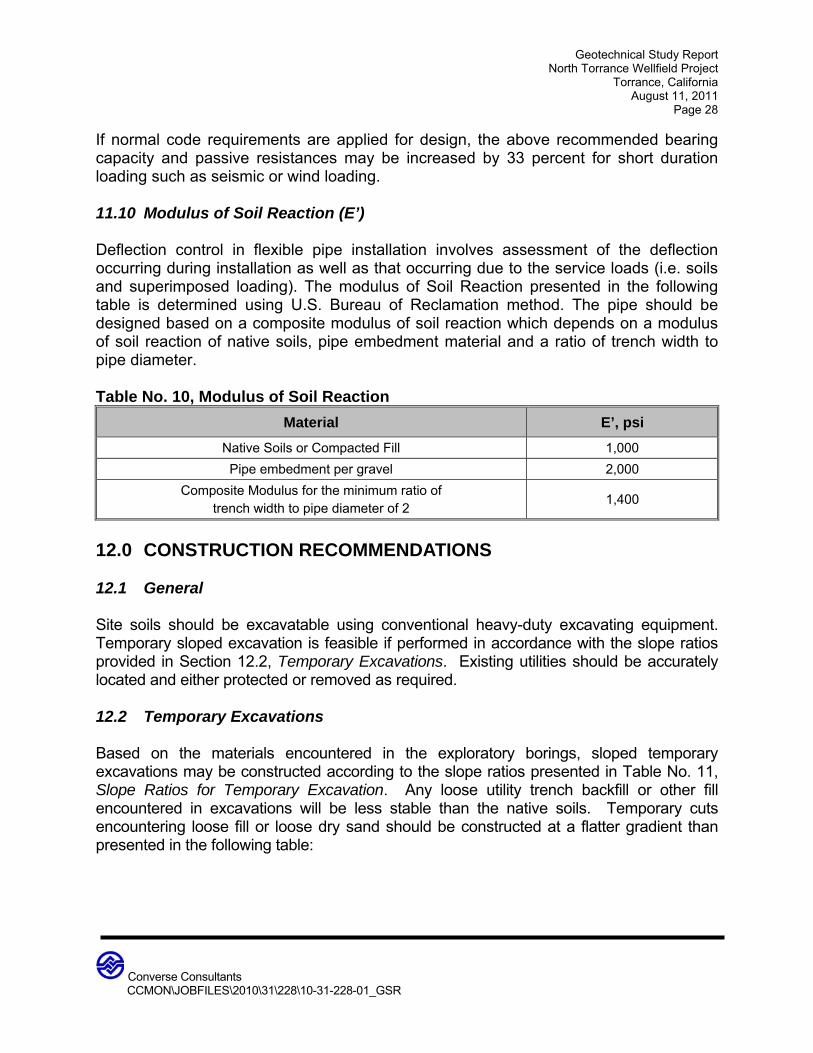
Geotechnical Study Report North Torrance Wellfield Project
Torrance, California August 11, 2011
Page 28
Converse Consultants
CCMON\JOBFILES\2010\31\228\10-31-228-01_GSR
If normal code requirements are applied for design, the above recommended bearing capacity and passive resistances may be increased by 33 percent for short duration loading such as seismic or wind loading. 11.10 Modulus of Soil Reaction (E’) Deflection control in flexible pipe installation involves assessment of the deflection occurring during installation as well as that occurring due to the service loads (i.e. soils and superimposed loading). The modulus of Soil Reaction presented in the following table is determined using U.S. Bureau of Reclamation method. The pipe should be designed based on a composite modulus of soil reaction which depends on a modulus of soil reaction of native soils, pipe embedment material and a ratio of trench width to pipe diameter. Table No. 10, Modulus of Soil Reaction
Material E’, psi
Native Soils or Compacted Fill 1,000
Pipe embedment per gravel 2,000
Composite Modulus for the minimum ratio of trench width to pipe diameter of 2
1,400
12.0 CONSTRUCTION RECOMMENDATIONS 12.1 General Site soils should be excavatable using conventional heavy-duty excavating equipment. Temporary sloped excavation is feasible if performed in accordance with the slope ratios provided in Section 12.2, Temporary Excavations. Existing utilities should be accurately located and either protected or removed as required. 12.2 Temporary Excavations Based on the materials encountered in the exploratory borings, sloped temporary excavations may be constructed according to the slope ratios presented in Table No. 11, Slope Ratios for Temporary Excavation. Any loose utility trench backfill or other fill encountered in excavations will be less stable than the native soils. Temporary cuts encountering loose fill or loose dry sand should be constructed at a flatter gradient than presented in the following table:
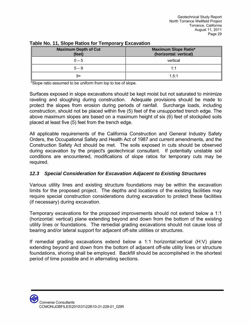
Geotechnical Study Report North Torrance Wellfield Project
Torrance, California August 11, 2011
Page 29
Converse Consultants
CCMON\JOBFILES\2010\31\228\10-31-228-01_GSR
Table No. 11, Slope Ratios for Temporary Excavation Maximum Depth of Cut
(feet) Maximum Slope Ratio*
(horizontal: vertical)
0 – 5 vertical
5 – 9 1:1
9+ 1.5:1
*Slope ratio assumed to be uniform from top to toe of slope. Surfaces exposed in slope excavations should be kept moist but not saturated to minimize raveling and sloughing during construction. Adequate provisions should be made to protect the slopes from erosion during periods of rainfall. Surcharge loads, including construction, should not be placed within five (5) feet of the unsupported trench edge. The above maximum slopes are based on a maximum height of six (6) feet of stockpiled soils placed at least five (5) feet from the trench edge. All applicable requirements of the California Construction and General Industry Safety Orders, the Occupational Safety and Health Act of 1987 and current amendments, and the Construction Safety Act should be met. The soils exposed in cuts should be observed during excavation by the project's geotechnical consultant. If potentially unstable soil conditions are encountered, modifications of slope ratios for temporary cuts may be required. 12.3 Special Consideration for Excavation Adjacent to Existing Structures Various utility lines and existing structure foundations may be within the excavation limits for the proposed project. The depths and locations of the existing facilities may require special construction considerations during excavation to protect these facilities (if necessary) during excavation. Temporary excavations for the proposed improvements should not extend below a 1:1 (horizontal: vertical) plane extending beyond and down from the bottom of the existing utility lines or foundations. The remedial grading excavations should not cause loss of bearing and/or lateral support for adjacent off-site utilities or structures. If remedial grading excavations extend below a 1:1 horizontal:vertical (H:V) plane extending beyond and down from the bottom of adjacent off-site utility lines or structure foundations, shoring shall be employed. Backfill should be accomplished in the shortest period of time possible and in alternating sections.
Geotechnical Study Report North Torrance Wellfield Project
Torrance, California August 11, 2011
Page 30
Converse Consultants
CCMON\JOBFILES\2010\31\228\10-31-228-01_GSR
12.4 Temporary Shoring Due to site constraints (such as roadway pavement), sloped and/or stepped excavations may not always be feasible, thus requiring the need for shoring during construction. Shoring may consist of the use of a trench box (where feasible), and/or sheet piles. The shoring for pipeline excavations and trenchless construction jacking/receiving pits may be cantilevered or may be laterally supported by whalers and cross bracing. The shoring system should be designed to limit a maximum wall deflection of ½ inch. Earth materials encountered in our borings within the anticipated construction zone consist of predominately clay soils. In consideration of the predominately clayey nature of the site soils, caving is not anticipated. 12.4.1 Cantilevered Shoring Cantilevered shoring systems may include sheet piles to maintain temporary support of vertical wall excavations. Shoring design must consider the support of adjacent underground utilities and/or structures, and should consider the effects of shoring deflection on supported improvements. Temporary cantilevered shoring should be designed to resist a lateral earth pressure equivalent to a fluid density of 30 pounds per cubic foot (pcf) for non-surcharged condition above groundwater level.
Surcharge pressures from the existing structures should be added to the above earth pressures for surcharges within a horizontal distance less than or equal to the wall height. Surcharge coefficients of 45% of any uniform vertical surcharge should be added as a horizontal earth pressure for shoring design.
Surcharge pressures due to miscellaneous loads, such as vehicular traffic, soil stockpiles or construction equipments located adjacent to the shoring, should be included in the upper 10 feet of the shoring to account for normal vehicular and construction traffic within 10 feet of the excavation. Regular traffic surcharge can be considered as 100 psf for the upper 10 fee of shoring excavation. Construction surcharge of 500 psf should be considered for the heavy construction vehicle/equipment. All shoring should be designed and installed in accordance with state and federal safety regulations.
Lateral resistance for sheet piles can be provided by passive pressure below the bottom of excavations. The allowable passive pressure for soldier piles can be taken as an equivalent fluid pressure of 300 psf on the pile per foot of depth, measured below the bottom of excavation. The allowable maximum passive resistance should not exceed 3,000 psf.

Geotechnical Study Report North Torrance Wellfield Project
Torrance, California August 11, 2011
Page 31
Converse Consultants
CCMON\JOBFILES\2010\31\228\10-31-228-01_GSR
All shoring system should be designed by experienced California licensed Civil Engineer and installed by experienced contractors. Shoring design should also be reviewed by Geotechnical Consultant to verify the soil parameters used in the design conformance with geotechnical report. All applicable requirements of the California Construction and General Industry Safety Orders, the Occupational Safety and Health Act of 1987 and current amendments, and the Construction Safety Act should be met. The soils exposed in cuts should be observed during excavation by a competent person employed by the contractor. If potentially unstable soil conditions are encountered, modifications of slope ratios for temporary cuts may be required. It is recommended that Converse review plans and specifications for proposed shoring and that a Converse representative observes the installation of shoring. A licensed surveyor should be retained to establish monuments on shoring and the surrounding ground prior to excavation. Such monuments should be monitored for horizontal and vertical movement during construction. Results of the monitoring program should be provided immediately to the project Structural (shoring) Engineer and Converse for review and evaluation. Adjacent building elements should be photo-documented prior to construction. 12.5 Trenchless Construction Based on our understanding of the project, trenchless techniques may be utilized for the drain pipeline planned below the Caltrans right-of-way. The results of our subsurface exploration indicate relatively firm clay soils and deep groundwater for this area. It is our opinion that trenchless construction at this location can be accomplished by an experienced contractor using pipe jacking/micro-tunneling equipment. Pipe jacking and micro-tunneling operations involve the initial construction of a jacking/tunneling pit and a receiving pit at each end of the pipe segment to be jacked. Micro-tunneling occupies a position at the heavy end of trenchless technology, and can be regarded as an extension of pipe jacking where a new pipe is pushed through a hole excavated ahead of the advancing pipe string. Whereas traditional pipe jacking requires a team of workers at the face, micro-tunneling replaces this manual work with a small tunnel boring machine (TBM). The working/access shafts are utilized to remove the spoil and to transport the construction materials and personnel for a tunnel project. The vertical face of the working shaft should be supported with shoring. Frequent contact grouting may be necessary to backpack the shoring during construction to minimize settlement.
Geotechnical Study Report North Torrance Wellfield Project
Torrance, California August 11, 2011
Page 32
Converse Consultants
CCMON\JOBFILES\2010\31\228\10-31-228-01_GSR
Grouting through the pipe casing after jacking is recommended to fill any possible voids created by the jacking operation. Jacking operations and tunneling operations should be performed in accordance with the Standard Specifications for Public Works Construction, Sections 306-2 and 306-3 to the latest edition. Consideration should be given to performing a pre-condition survey of improvements in the area prior to construction, to document any current existing distress. Settlement points should be considered to monitor any settlement of adjacent facilities during construction. Excavation and shoring systems should be properly designed and installed to minimize the effect of settlement during construction. The preparation of plans for the excavation and shoring is normally the responsibility of the contractor. Such plans should be submitted to the engineer for review prior to construction. Consideration should be given to characterize the material during the excavation of tunnel and based on the behavior of the soil the support system and method of trenchless may be altered accordingly. It is the contractor’s responsibility to design and select the appropriate tunnel construction method, support system and to follow the requirements of the health and safety rules of the State of California pertaining to micro-tunnel construction and permit requirement of local agencies. 12.6 Geotechnical Services During Construction This report has been prepared to aid in the site preparation and site grading plans and specifications, and to assist the architect, civil and structural engineers in the design of the proposed structures. It is recommended that this office be provided an opportunity to review final design drawings and specifications to verify that the recommendations of this report have been properly implemented. Recommendations presented herein are based upon the assumption that adequate earthwork monitoring will be provided by a geotechnical consultant. Excavation bottoms should be observed by a Converse representative prior to the placement of compacted fill. Structural fill and backfill should be placed and compacted during continuous observation and testing by a geotechnical consultant. Footing excavations should be observed by a geotechnical consultant prior to placement of steel and concrete so that footings are founded on satisfactory materials and excavations are free of loose and disturbed materials. During construction, the geotechnical engineer and/or their authorized representatives should be present at the site to provide a source of advice to the client regarding the geotechnical aspects of the project and to observe and test the earthwork performed.
Geotechnical Study Report North Torrance Wellfield Project
Torrance, California August 11, 2011
Page 33
Converse Consultants
CCMON\JOBFILES\2010\31\228\10-31-228-01_GSR
Their presence should not be construed as an acceptance of responsibility for the performance of the completed work, since it is the sole responsibility of the contractor performing the work to ensure that it complies with all applicable plans, specifications, ordinances, etc. This firm does not practice or consult in the field of safety engineering. We do not direct the contractor’s operations, and cannot be responsible for other than our own personnel on the site; therefore, the safety of others is the responsibility of the contractor. 13.0 CLOSURE The findings and recommendations of this report were prepared in accordance with generally accepted professional engineering and engineering geologic principles and practice. We make no other warranty, either expressed or implied. Our conclusions and recommendations are based on the results of the background review, field and laboratory studies, combined with an interpolation and extrapolation of soil conditions between and beyond boring locations. If conditions encountered during construction appear to be different from those shown by the borings, this office should be notified. Design recommendations given in this report are based on the assumption that the earthwork and site grading recommendations contained in this report are implemented. Additional consultation may be prudent to interpret Converse's findings for contractors, or to possibly refine these recommendations based upon the review of the final site grading and actual site conditions encountered during construction. If the scope of the project changes, if project completion is to be delayed, or if the report is to be used for another purpose, this office should be consulted. This geotechnical report was prepared for AECOM to aid in the design and construction of the project elements described herein. Converse is not responsible for technical interpretations made by others of our exploratory information. Specific questions or interpretations concerning the findings and conclusions presented herein may require a written clarification to avoid any misunderstandings.

Geotechnical Study Report North Torrance Wellfield Project
Torrance, California August 11, 2011
Page 34
Converse Consultants
CCMON\JOBFILES\2010\31\228\10-31-228-01_GSR
14.0 REFERENCES AMERICAN SOCIETY OF CIVIL ENGINEERS, ASCE/SEI 7-05, Minimum Design
Loads for Structures and Other Structures, copyright 2006. ASTM INTERNATIONAL, Annual Book of ASTM Standards, Current. BLAKE, T. F., 2000, UBCSEIS, FRISKSP, and EQSEARCH Computer Programs for
Performing Probabilistic, and Seismic Coefficient Analysis and Historical Earthquake Search, using 2002 CGS Fault Model, Computer Model Files, CGS Source Data, Maps for Performing Probabilistic Seismic Hazard Analysis.
BRANUM, D., et. al., 2008, Earthquake Shaking Potential for California, Map Sheet 48,
California Geologic Survey. CALIFORNIA BUILDING STANDARDS COMMISSION, 2010, California Building Code
(CBC), California Code of Regulations Title 24, Part 2, Volumes 1 and 2, effective date January 2011.
CALIFORNIA DEPARTMENT OF TRANPORTATION, 2003, Corrosion Guidelines,
Version 1.0, dated September, 2003. CALIFORNIA DIVISION OF MINES AND GEOLOGY, Fault-Rupture Hazard Zones in
California, Alquist-Priolo Earthquake Faulting Zoning Act with Index to Earthquake Fault Zone Maps, Special Publication 42, Revised 1997, Supplements 1 and 2 added 1999, Supplement 3 added in 2003.
CALIFORNIA DIVISION OF MINES AND GEOLOGY, 1998, Seismic Hazard Zone
Report for the Torrance 7.5-Minute Quadrangles, Los Angeles County, California, Seismic Hazard Zone Report 035.
CALIFORNIA DIVISION OF MINES AND GEOLOGY, 1999, Seismic Hazard Zones
Map, Torrance 7.5-Minute Quadrangle, Los Angeles County, California, Official Map dated March 25, 1999.
CALIFORNIA GEOLOGIC SURVEY, 2003, Geologic Map of the Long Beach 30’ x 60’
Quadrangle, Version 1.0, dated January 1, 2011. CALIFORNIA GEOLOGIC SURVEY, Guidelines for Evaluating and Mitigating Seismic
Hazards in California, Special Publication 117A, 2008.

Geotechnical Study Report North Torrance Wellfield Project
Torrance, California August 11, 2011
Page 35
Converse Consultants
CCMON\JOBFILES\2010\31\228\10-31-228-01_GSR
CALIFORNIA GEOLOGIC SURVEY – Note 48, 2011, Checklist for the Review of Engineering Geology and Seismology Reports for California Public Schools, Hospitals, and Essential Services Structures, dated January 1, 2011.
CAO, T., et. al., 2003, The Revised 2002 California Probabilistic Seismic Hazard Maps,
June 2003, pp. 1-11, Appendix A. CIVILTECH SOFTWARE, LiquefyPro, Version 5.8d, A Computer Program for
Computation of Liquefaction and Seismic Settlements.
CIVILTECH SOFTWARE, AllPile, Version 7.9a, A Computer Program for Pile Analysis.
DAY, Robert W., 2006, Foundation Engineering Handbook. DEPARTMENT OF THE NAVY, Naval Facilities Engineering Command, Alexandria,
VA, SOIL MECHANICS, DESIGN MANUAL 7.01 (NAVFAC DM-7.01), 1982. DEPARTMENT OF THE NAVY, Naval Facilities Engineering Command, Alexandria,
VA, FOUNDATIONS AND EARTH BUILDINGS, DESIGN MANUAL 7.02 (NAVFAC DM-7.02), 1986.
DOLAN, J.F., SIEH, K., ROCKWELL, T.K., GUPTILL, P., and MILLER G., 1997, Active
Tectonics, Paleoseismology, and Seismic Hazards of the Hollywood Fault, Northern Los Angeles Basin, California: GSA Bulletin, v. 109, p. 1595-1616.
DOLAN, J.F., et. al., 2003, Recognition of Paleo Earthquakes on the Puente Hills Blind
Thrust Fault, California, April 4, 2003, Science, Vol. 300, pp. 115-118. EZ-FRISK, Version 7.32, 2009, “Software for Earthquake Ground Motion Estimation”,
Risk Engineering, Inc. NATIONAL CENTER FOR EARTHQUAKE ENGINEERING RESEARCH (NCEER),
Proceedings of the NCEER Workshop on Evaluation of Liquefaction Resistance of Soils, Edited by T. L. Youd and I. M. Idriss, Technical Report NCEER-97-0022, 1997.
PORTLAND CEMENT ASSOCIATION, Southwest Region Publication P-14, Portland
Cement Concrete Pavement Design Nomograph for City and County Roads. SEED, H.B. AND WHITMAN, R. V. 1970. Design of Earth Retaining Structures for
Dynamic Loads, ASCE Specialty Conference, Lateral Stresses in the Ground and Design of Earth Retaining Structures, p.103-147.

Geotechnical Study Report North Torrance Wellfield Project
Torrance, California August 11, 2011
Page 36
Converse Consultants
CCMON\JOBFILES\2010\31\228\10-31-228-01_GSR
SHAW, J.H., et al., 2002, Puente Hills Blind-Thrust System, Los Angeles, California: Bulletin of the Seismological Society of America, December 2002, v. 92, no. 8, p. 2946-2960.
SOUTHERN CALIFORNIA EARTHQUAKE CENTER, Recommended Procedures for
Implementation of DMG Special Publication 117 Guidelines for Analyzing and Mitigating Liquefaction in California, March 1999.
STANDARD SPECIFICATIONS FOR PUBLIC WORKS CONSTRUCTION, 2009, Public
Works Standards, Inc. STATE OF CALIFORNIA DEPARTMENT OF TRANSPORTATION, California Tests 643,
422, 417 and 532. TOKIMATSU, K. AND SEED, H. B., 1987; Evaluation of Settlement in Sands Due to
Earthquake Shaking, ASCE Journal of Geotechnical Engineering, Vol. 118. TOPPOZADA, T., et. al., 2000, Epicenters of and Areas Damaged by M ≥ 5 California
Earthquakes, 1800-1999, Map Sheet 49, California Geologic Survey. UNITED STATES GEOLOGICAL SURVEY, 2011, Seismic Hazards Curves, Response
Parameters and Design Parameters, Version 5.1.0, Computer Program by the United States Geological Survey dated February 10, 2011.

APPENDIX A
FIELD EXPLORATION