10 assembly techniques category ii welding, adhesive ... · an ultrasonic or vibration welding...
TRANSCRIPT

ry II
Spin WeldingIntroductionRotation welding is the ideal method for making strongand tight joints between any thermoplastic parts whichhave symmetry of rotation. Engineers faced with the choiceof either the ultrasonic or the spinwelding process willunhesitatingly prefer the latter, in view of the followingadvantages which it presents:
1) The investment required for identical production islower with spinwelding than with ultrasonics. There are no special difficulties in construction themachinery from ordinary commercial machine parts,either wholly or partly in one’s own workshop.
2) The process is based on physical principles which canbe universally understood and mastered. Once thetools and the welding conditions have been chosencorrectly, results can be optimised merely by varyingone single factor, namely the speed.
3) The cost of electrical control equipment is modest,even for fully automatic welding.
4) There is much greater freedom in the design of theparts, and no need to worry about projecting edges,studs or ribs breaking off. Moulded in metal parts cannot work loose and damage any pre-assembledmechanical elements. Nor is it essential for the distrib-ution of mass in the parts to be symmetrical or uniform,as is the case with ultrasonic welding.
If the relative position of the two components matters, thenan ultrasonic or vibration welding process must be used.
But, in practice, there are often cases in which this isessential only because the component has been badlydesigned. Parts should, as far as possible, be designed in such a way that positioning of the two components relative to each other is unnecessary.
Basic PrinciplesIn spinwelding, as the name implies, the heat required forwelding is produced by a rotating motion, simultaneouslycombined with pressure, and therefore the process is suit-able only for circular parts. It is of course immaterial whichof the two halves is held fixed and which is rotated. If thecomponents are of different lengths, it is better to rotatethe shorter one, to keep down the length of the movingmasses.
In making a selection from the methods and equipmentdescribed in detail below, the decisive factors are thegeometry of the components, the anticipated output, andthe possible amount of capital investment.
10 – Assembly Techniques – CategoWelding, Adhesive Bonding
Because of the relatively small number of mechanicalcomponents needed, the equipment can sometimes beconstructed by the user himself. In this way, seriousdefects in the welding process can often be pinpointed,some examples of which will be described later.
Practical MethodsThe most commonly used methods can be divided roughlyinto two groups as follows:
Pivot WeldingDuring welding the device holding the rotating part isengaged with the driving shaft, the two parts being at thesame time pressed together. After completion of the weld-ing cycle, the rotating jig is disengaged from the shaft, butthe pressure is kept up for a short time, depending on thetype of plastic.
Inertia WeldingThe energy required for welding is first stored up in a fly-wheel, which is accelerated up to the required speed; thisflywheel also carries the jig and one of the plastic parts.Then the parts are forced together under high pressure, atwhich point the kinetic energy of the flywheel is convertedinto heat by friction, and it comes to a stop. In practicethis method has proved the more suitable one, and willtherefore be described in more detail.
Pivot Welding
Pivot Welding on a LatheEasily the simplest, but also the most cumbersome weld-ing method in this group, pivot welding can be carried outon any suitable sized lathe. Fig. 10.01 illustrates the set-up.
One of the parts to be welded, a, is clamped by b, whichmay be an ordinary chuck, a self-locking chuck, a com-pressed air device, or any other suitable device, so long as it grips the part firmly, centres and drives it.
The spring-loaded counterpoint c in the tailstock must be capable of applying the required pressure, and shouldbe able to recoil 5-10 mm. The cross-slide d should also,if possible, be equipped with a lever. The plastic part a1should have some sort of projecting rib, edge, etc., so thatthe stop e can prevent it from rotating.
91
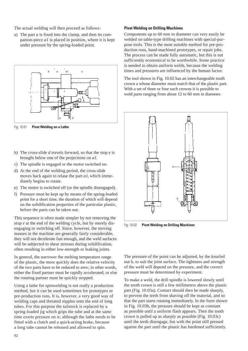
The actual welding will then proceed as follows:
a) The part a is fixed into the clamp, and then its com-panion-piece a1 is placed in position, where it is keptunder pressure by the spring-loaded point.
b) The cross-slide d travels forward, so that the stop e isbrought below one of the projections on a1.
c) The spindle is engaged or the motor switched on.
d) At the end of the welding period, the cross-slidemoves back again to relase the part a1, which imme-diately begins to rotate.
e) The motor is switched off (or the spindle disengaged).
f) Pressure must be kept up by means of the spring-loadedpoint for a short time, the duration of which will dependon the solidification properties of the particular plastic,before the parts can be taken out.
This sequence is often made simpler by not removing thestop e at the end of the welding cycle, but by merely dis-engaging or switching off. Since, however, the movingmasses in the machine are generally fairly considerable,they will not decelerate fast enough, and the weld surfaceswill be subjected to shear stresses during solidification,often resulting in either low-strength or leaking joints.
In general, the narrower the melting temperature range of the plastic, the more quickly does the relative velocityof the two parts have to be reduced to zero; in other words,either the fixed partner must be rapidly accelerated, or elsethe rotating partner must be quickly stopped.
Using a lathe for spinwelding is not really a productionmethod, but it can be used sometimes for prototypes orpre-production runs. It is, however, a very good way ofwelding caps and threated nipples onto the end of longtubes. For this purpose the tailstock is replaced by aspring-loaded jig which grips the tube and at the sametime exerts pressure on it; although the lathe needs to befitted with a clutch and a quick-acting brake, because a long tube cannot be released and allowed to spin.
92
ab a1 c
de
Fig. 10.01 Pivot Welding on a Lathe
Pivot Welding on Drilling MachinesComponents up to 60 mm in diameter can very easily bewelded on table-type drilling machines with special-pur-pose tools. This is the most suitable method for pre-pro-duction runs, hand-machined prototypes, or repair jobs.The process can be made fully automatic, but this is notsufficiently economical to be worthwhile. Some practiceis needed to obtain uniform welds, because the weldingtimes and pressures are influenced by the human factor.
The tool shown in Fig. 10.02 has an interchangeable toothcrown a whose diameter must match that of the plastic part.With a set of three or four such crowns it is possible toweld parts ranging from about 12 to 60 mm in diameter.
The pressure of the point can be adjusted, by the knurlednut b, to suit the joint surface. The tightness and strengthof the weld will depend on the pressure, and the correctpressure must be determined by experiment.
To make a weld, the drill spindle is lowered slowly untilthe tooth crown is still a few millimeters above the plasticpart (Fig. 10.03a). Contact should then be made sharply,to prevent the teeth from shaving off the material, and sothat the part starts rotating immediately. In the form shownin Fig. 10.03b, the pressure should be kept as constant as possible until a uniform flash appears. Then the toothcrown is pulled up as sharply as possible (Fig. 10.03c)until the teeth disengage, but with the point still pressedagainst the part until the plastic has hardened sufficiently.
Fig. 10.02 Pivot Welding on Drilling Machines
b
a

The function of the point, therefore, is merely to apply the appropriate pressure. All the same, the plastic partsshould be provided with a centering recess to guide the tool and to obtain uniform vibrationless rotation.
For a good weld a certain amount of heat is needed, whichwill depend on the plastic in question; it is a product ofthe pressure, the speed and the cycle time. At the sametime, the product of pressure times speed must not bebelow a certain minimum value, or else the joint faceswill only wear without reaching the melting point. The coefficient of friction is important too. Clearly allthese factors vary from one plastic to another, and mustbe determined for each case. (For the shape and arrange-ment of the driving teeth, see Chapter 7).
As a first approximation, the peripheral welding speed for DELRIN® and ZYTEL® should be chosen between 3 and 5 m / s. Then the pressure must be adjusted untilthedesired result is obtained in a welding time of 2 to 3 seconds.
For good results, a correct weld profile is of course essen-tial. For suggestions and dimensions, see Chapter 8.
Pivot Welding on Specially Designed MachinesTo make the method we have just described fully auto-matic involves a certain amount of machine investment,so that it is now very rarely used in large-scale produc-tion. But special machines, based on an adaptation of thismethod, have been built which are much easier to operate(Fig. 10.04).
Fig. 10.03 Drill spindle positions
a
b
c
The machine has an electromagnetic clutch a, which makesit very easy to engage and disengage the working spindleb, which rotates in a tube c which also carries the air-piston d. The head e can take either a tooth crown or oneof the other jigs described in a later section, depending on the particular plastic component to be welded.
The welding procedure is as follows:
– Both parts are inserted into the bottom holder f.
– The piston (operated by compressed air) and its work-ing spindle are lowered.
– The clutch engages, causing the top plastic part to rotate.
– After a certain period (controlled by a timer) the clutchdisengages, but pressure continues to be applied for a further period (depending on the type of plastic).
– The spindle is raised and the welded article ejected (or the turntable switched to the next position).
In suitable cases, a tooth crown may be employed to gripthe part (Fig. 10.16). Alternatively, projections on the part such as ribs, pins, etc., can be employed for driving,because the spindle is not engaged until after the part hasbeen gripped.
93
Fig. 10.04 Pivot Welding on Special Machines
b
a
c
d
e
f
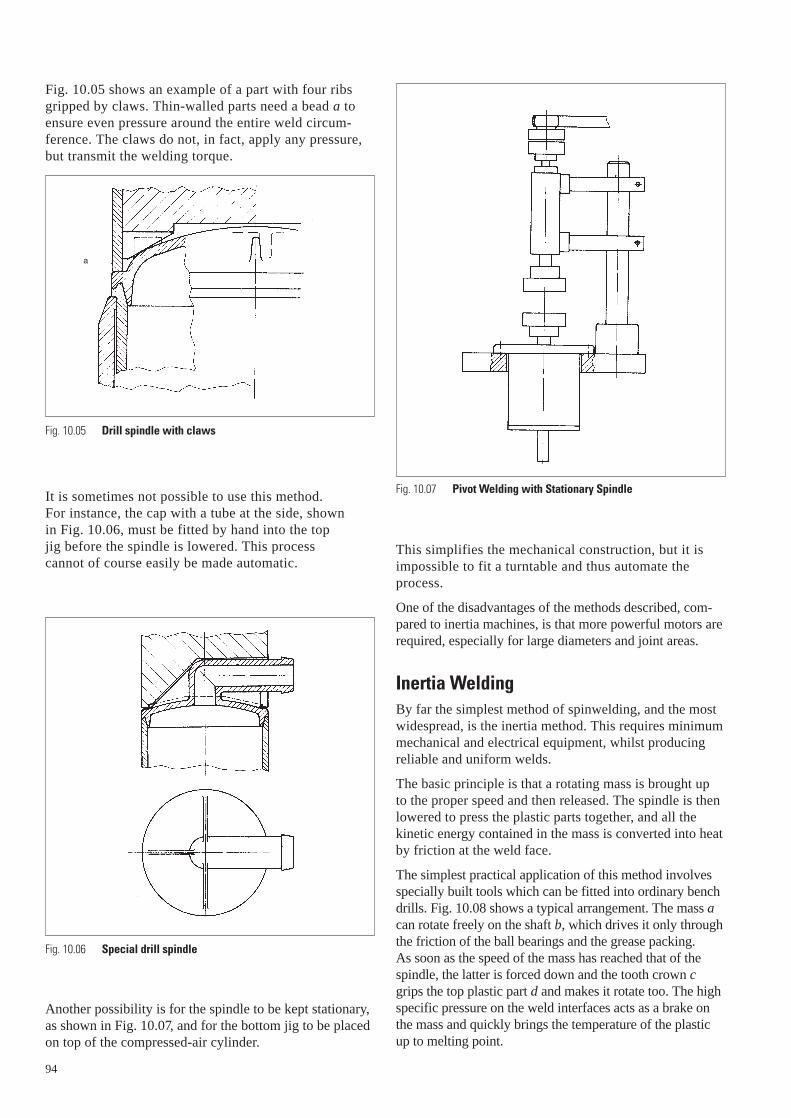
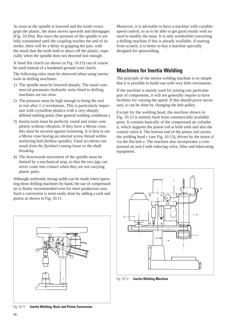
Fig. 10.05 shows an example of a part with four ribs gripped by claws. Thin-walled parts need a bead a toensure even pressure around the entire weld circum-ference. The claws do not, in fact, apply any pressure, but transmit the welding torque.
It is sometimes not possible to use this method. For instance, the cap with a tube at the side, shown in Fig. 10.06, must be fitted by hand into the top jig before the spindle is lowered. This process cannot of course easily be made automatic.
Another possibility is for the spindle to be kept stationary,as shown in Fig. 10.07, and for the bottom jig to be placedon top of the compressed-air cylinder.
94
a
Fig. 10.05 Drill spindle with claws
Fig. 10.06 Special drill spindle
This simplifies the mechanical construction, but it isimpossible to fit a turntable and thus automate theprocess.
One of the disadvantages of the methods described, com-pared to inertia machines, is that more powerful motors arerequired, especially for large diameters and joint areas.
Inertia WeldingBy far the simplest method of spinwelding, and the mostwidespread, is the inertia method. This requires minimummechanical and electrical equipment, whilst producingreliable and uniform welds.
The basic principle is that a rotating mass is brought up to the proper speed and then released. The spindle is thenlowered to press the plastic parts together, and all thekinetic energy contained in the mass is converted into heatby friction at the weld face.
The simplest practical application of this method involvesspecially built tools which can be fitted into ordinary benchdrills. Fig. 10.08 shows a typical arrangement. The mass acan rotate freely on the shaft b, which drives it only throughthe friction of the ball bearings and the grease packing. As soon as the speed of the mass has reached that of thespindle, the latter is forced down and the tooth crown cgrips the top plastic part d and makes it rotate too. The highspecific pressure on the weld interfaces acts as a brake onthe mass and quickly brings the temperature of the plasticup to melting point.
Fig. 10.07 Pivot Welding with Stationary Spindle

Once again, pressure must be kept on for a short period,depending on the particular type of plastic.
The tool illustrated in Fig. 10.08 has no mechanical coup-ling, so that a certain period of time (which depends onthe moment of inertia and the speed of the spindle)mustelapse before the mass has attained the necessaryspeed for the next welding operation, and with largertools or an automatic machine this would be too long.Moreover, there is a danger – especially when operatingby hand – that the next welding cycle will be commencedbefore the mass has quite reached its proper speed, result-ing in a poor quality weld. The tool shown in Fig. 10.08should therefore only be used for parts below a certainsize (60-80 mm in diameter).
Since small components can also be welded with fly-wheelsif high speeds are used, very small tools (30-50 mm in dia-meter) are sometimes constructed which will fit straight intothe drill chuck. Fig. 10.09 shows such an arrangement, forwelding plugs. Since speeds as high as 8000 to 10000 rpmare needed, a pivot tool like that in Fig. 10.02 is sometimespreferred.
For tools with diameters over 60-80 mm, or where a rapidwelding cycle is required, a mechanical coupling like inFig. 10.10 is best. Here the mass a can move up and downthe shaft b. When idling, the springs c force the massdown so that it engages with the shaft via the cone cou-pling d. The mass then takes only an instant to get up toits working speed.
Fig. 10.08 Inertia Welding using ordinary bench drills
b
a
c
d
95
Fig. 10.09 Inertia Welding for small components
Fig. 10.10 Inertia Welding, Mechanical Coupling
b
d
a
c
As soon as the spindle is lowered and the tooth crowngrips the plastic, the mass moves upwards and disengages(Fig. 10.10a). But since the pressure of the spindle is notfully transmitted until the coupling reaches the end of itsstroke, there will be a delay in gripping the part, with the result that the teeth tend to shave off the plastic, espe-cially when the spindle does not descend fast enough.
A lined flat clutch (as shown in Fig. 10.13) can of coursebe used instead of a hardened ground cone clutch.
The following rules must be observed when using inertiatools in drilling machines:
1) The spindle must be lowered sharply. The usual com-mercial pneumatic-hydraulic units fitted to drillingmachines are too slow.
2) The pressure must be high enough to bring the tool to rest after 1-2 revolutions. This is particularly impor-tant with crystalline plastics with a very sharplydefined melting point. (See general welding conditions.)
3) Inertia tools must be perfectly round and rotate com-pletely without vibration. If they have a Morse cone,this must be secured against loosening. It is best to usea Morse cone having an internal screw thread withinanchoring bolt (hollow spindle). Fatal accidents canresult from the flywheel coming loose or the shaftbreaking.
4) The downwards movement of the spindle must be limited by a mechanical stop, so that the two jigs cannever come into contact when they are not carryingplastic parts.
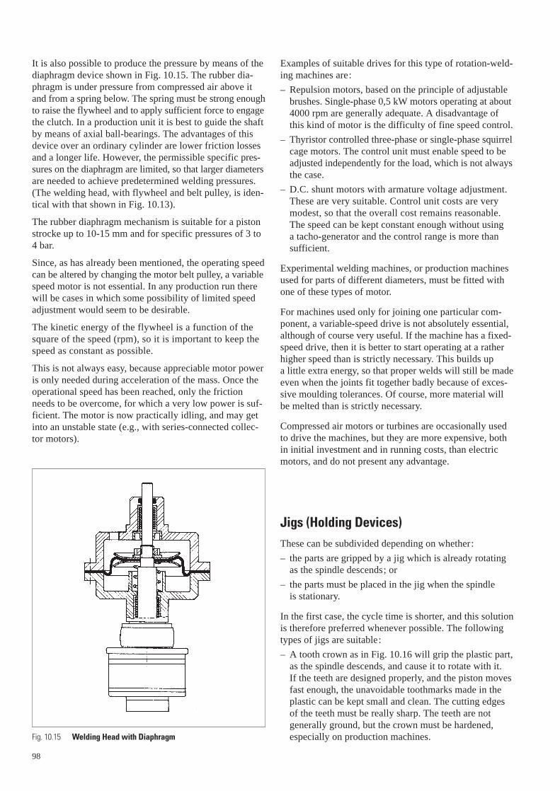
Although uniformly strong welds can be made when opera-ting these drilling machines by hand, the use of compressedair is firmly recommended even for short production runs.Such a conversion is most easily done by adding a rack andpinion as shown in Fig. 10.11.
96
Fig. 10.11 Inertia Welding, Rack and Pinion Conversion
Moreover, it is advisable to have a machine with variable-speed control, so as to be able to get good results with noneed to modify the mass. It is only worthwhile convertinga drilling machine if this is already available; if startingfrom scratch, it is better to buy a machine speciallydesigned for spinwelding.
Machines for Inertia WeldingThe principle of the inertia welding machine is so simplethat it is possible to build one with very little investment.
If the machine is mainly used for joining one particularpair of components, it will not generally require to havefacilities for varying the speed. If this should prove neces-sary, it can be done by changing the belt pulley.
Except for the welding head, the machine shown in Fig. 10.12 is entirely built from commercially availableparts. It consists basically of the compressed air cylindera, which supports the piston rod at both ends and also thecontrol valve b. The bottom end of the piston rod carriesthe welding head c (see Fig. 10.13), driven by the motor dvia the flat belt e. The machine also incorporates a com-pressed air unit f with reducing valve, filter and lubricatingequipment.
a
b
c
d
e
f
Fig. 10.12 Inertia Welding Machine

The welding head shown in Fig. 10.13 (designed by DuPont)consists of a continuously rotating belt pulley a, whichcarries the coupling lining b. In the drawing, the pistonrod is at the top of its stroke and the movement of rotationis transmitted via the coupling to the flywheel c.
As the spindle descends, the coupling disengages and thetooth crown grips the top of the float, shown as an example.
If it is impossible to grip the part with a tooth crown, and it has to be fitted into the top jig by hand (as in Fig. 10.06,for example), an extra control will be necessary. The pis-ton will have to pause on the upstroke just before the coup-ling engages, to enable the parts to be inserted. This canbe managed in various ways. For example, one can buycompressed air cylinders fitted with such a device. A pulsepasses from the travelling piston directly to a Reed switchon the outside.
So that the parts may be taken out conveniently, the pis-ton stroke must generally be about 1,2 times the length ofthe entire finished welded part. Long parts require consid-erable piston strokes, which is impractical and expensive.Fig. 10.14 shows a typical example – a fire-extinguisher –for which a piston stroke 1,2 times the length of the partwould normally have been needed.
However, there are various ways of circumventing this:
1) The bottom holder a, can be fitted with a device forclamping and centering, so that it can easily bereleased by hand and taken out sideways.
Fig. 10.13 Inertia Welding Machine Head
a
b
c
d
2) Two holders are fitted, a and b, which can swivelthrough 180° about the axis X-X by means of a turn-table c. The completed article is removed and changedwhile the next one is being welded; this reduces thetotal welding cycle.
3) If the production run justifies it, a turntable can ofcourse be used; it may, for instance, have three posi-tions: welding, removal and insertion.
The above steps allow the piston stroke to be shortenedconsiderably, thus avoiding the potentially lethal arrange-ment of having the rotating mass on a piston rod whichprojects too far.
Since the welding pressure is fairly high, the clutch liningand the ball-bearings of the pulley will be under anunnecessarily heavy load when in the top position. It istherefore advisable to operate at two different pressures,although this does involve a more complicated pneumaticcontrol. Alternatively, a spiral spring can be incorporatedabove the piston, to take up some of the pressure at thetop of its stroke.
In any case, the speed of the piston must be reducedsharply just before contact is made, so as to reduce theinitial acceleration of the flywheel and protect the clutchlining.
On machines equipped with a turntable the parts areejected after being removed from under the spindle. In such cases, the piston stroke can be much shorter, as, for example, with the float shown in Fig. 10.13.
97
Fig. 10.14 Inertia Welding, long parts
L1
a
c
L
b
X
X
It is also possible to produce the pressure by means of thediaphragm device shown in Fig. 10.15. The rubber dia-phragm is under pressure from compressed air above itand from a spring below. The spring must be strong enoughto raise the flywheel and to apply sufficient force to engagethe clutch. In a production unit it is best to guide the shaftby means of axial ball-bearings. The advantages of thisdevice over an ordinary cylinder are lower friction lossesand a longer life. However, the permissible specific pres-sures on the diaphragm are limited, so that larger diametersare needed to achieve predetermined welding pressures.(The welding head, with flywheel and belt pulley, is iden-tical with that shown in Fig. 10.13).
The rubber diaphragm mechanism is suitable for a pistonstrocke up to 10-15 mm and for specific pressures of 3 to4 bar.
Since, as has already been mentioned, the operating speedcan be altered by changing the motor belt pulley, a variablespeed motor is not essential. In any production run therewill be cases in which some possibility of limited speedadjustment would seem to be desirable.
The kinetic energy of the flywheel is a function of thesquare of the speed (rpm), so it is important to keep thespeed as constant as possible.
This is not always easy, because appreciable motor poweris only needed during acceleration of the mass. Once theoperational speed has been reached, only the frictionneeds to be overcome, for which a very low power is suf-ficient. The motor is now practically idling, and may getinto an unstable state (e.g., with series-connected collec-tor motors).
Fig. 10.15 Welding Head with Diaphragm
98
Examples of suitable drives for this type of rotation-weld-ing machines are:
– Repulsion motors, based on the principle of adjustablebrushes. Single-phase 0,5 kW motors operating at about4000 rpm are generally adequate. A disadvantage ofthis kind of motor is the difficulty of fine speed control.
– Thyristor controlled three-phase or single-phase squirrelcage motors. The control unit must enable speed to beadjusted independently for the load, which is not alwaysthe case.
– D.C. shunt motors with armature voltage adjustment.These are very suitable. Control unit costs are verymodest, so that the overall cost remains reasonable. The speed can be kept constant enough without using a tacho-generator and the control range is more thansufficient.
Experimental welding machines, or production machinesused for parts of different diameters, must be fitted withone of these types of motor.
For machines used only for joining one particular com-ponent, a variable-speed drive is not absolutely essential,although of course very useful. If the machine has a fixed-speed drive, then it is better to start operating at a ratherhigher speed than is strictly necessary. This builds up a little extra energy, so that proper welds will still be madeeven when the joints fit together badly because of exces-sive moulding tolerances. Of course, more material willbe melted than is strictly necessary.
Compressed air motors or turbines are occasionally usedto drive the machines, but they are more expensive, bothin initial investment and in running costs, than electricmotors, and do not present any advantage.
Jigs (Holding Devices)These can be subdivided depending on whether:
– the parts are gripped by a jig which is already rotatingas the spindle descends; or
– the parts must be placed in the jig when the spindle is stationary.
In the first case, the cycle time is shorter, and this solutionis therefore preferred whenever possible. The followingtypes of jigs are suitable:
– A tooth crown as in Fig. 10.16 will grip the plastic part,as the spindle descends, and cause it to rotate with it. If the teeth are designed properly, and the piston movesfast enough, the unavoidable toothmarks made in theplastic can be kept small and clean. The cutting edgesof the teeth must be really sharp. The teeth are not generally ground, but the crown must be hardened,especially on production machines.

– The dimensions indicated in Fig. 10.17 are intended to be approximate; dimensions should be matchedto the diameter of the part. With very thin-walled parts,it is better to reduce the distance between the teethtoensure that enough pressure is exerted on the joint.
– With larger or more complicated jigs it is better to designthe tooth crown as a separate part which can be changedif necessary.
– Fig. 10.18 shows two typical weld sections with theircorresponding tooth crowns and jigs.
– If the joints have no protruding bead, the bottom holdera, must fit closely, so as to prevent the part from expand-ing (especially if the wall is thin). The top of the plasticpart, b, should if possible have a rounded bead, to makeit easier for the teeth c to grip. With inertia-type machines, an outer ring d is oftennecessary to centre the part accurately, especially ifthere is too much play between the bottom plastic partand its holder, or if the piston-rod guides are worn.
30°
1-2
~ 4-8 ~ 3-6
b
d
a
c
s
1-2 mm
Fig. 10.16 Jig Tooth Crown
Fig. 10.17 Suggested Tooth Dimensions
Fig. 10.18 Typical Weld Sections
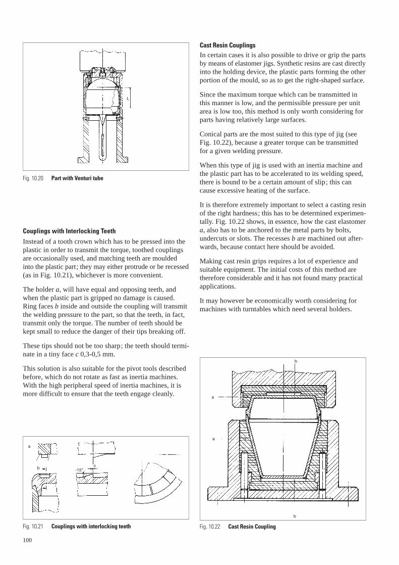
– The bottom half of the plastic part can be fitted with anidentical tooth crown (see also Figs. 10.13 and 10.20)to prevent its rotating. With the Venturi tube shown inFig. 10.19, its side part is used for retention. Obviouslythis makes automatic insertion very difficult, if notimpossible. The lower part is about 200 mm long, whichin itself would make automation too complicated. Thisis a good example of what was said before about theminimum lenght of piston stroke. Since the total lengthof the welded parts is about 300 mm, the piston strokewould have to be about 350 mm; a machine like thiswould be impractical and expensive; and the rotatingflywheel on the long piston-rod would be very danger-ous. This problem could be avoided by using a turn-table, but this would not be very practical either, becausethe parts are so long.
– The arrangement suggested in the drawing shows aholder a, which embraces one half of the part only, theother being held by a pneumatic device b. This enablesthe piston-stroke to be kept short, and the parts are easily inserted and removed. In addition, the joints aresupported around their entire circumference.
– Frequently the tooth crown cannot be sited immediatelyabove the weld; e.g., with the float shown in Fig. 10.20this is impossible for technical reasons. In such casesthe length L, i.e. the distance between weld and toothcrown, must be in proportion to the wall thickness, so that the high torque and the welding pressure can be taken up without any appreciable deformation. Thiswill of course also apply to the bottom plastic part.
– Selection of the joint profile and of the jig is often governed by the wall thickness.
99
Fig. 10.19 Part with Venturi tube
a
b
Couplings with Interlocking Teeth
Instead of a tooth crown which has to be pressed into theplastic in order to transmit the torque, toothed couplingsare occasionally used, and matching teeth are mouldedinto the plastic part; they may either protrude or be recessed(as in Fig. 10.21), whichever is more convenient.
The holder a, will have equal and opposing teeth, andwhen the plastic part is gripped no damage is caused.Ring faces b inside and outside the coupling will transmitthe welding pressure to the part, so that the teeth, in fact,transmit only the torque. The number of teeth should bekept small to reduce the danger of their tips breaking off.
These tips should not be too sharp; the teeth should termi-nate in a tiny face c 0,3-0,5 mm.
This solution is also suitable for the pivot tools describedbefore, which do not rotate as fast as inertia machines.With the high peripheral speed of inertia machines, it ismore difficult to ensure that the teeth engage cleanly.
100
Fig. 10.20 Part with Venturi tube
a
b c-15°
Fig. 10.21 Couplings with interlocking teeth
L
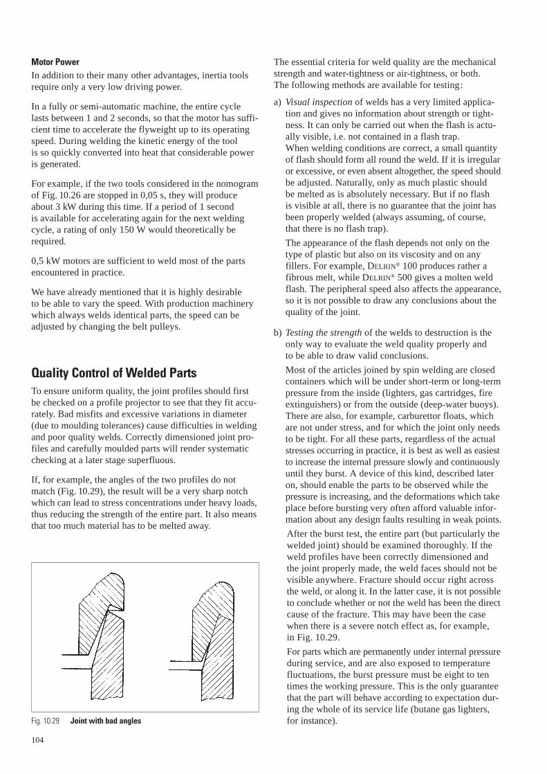
Cast Resin CouplingsIn certain cases it is also possible to drive or grip the partsby means of elastomer jigs. Synthetic resins are cast directlyinto the holding device, the plastic parts forming the otherportion of the mould, so as to get the right-shaped surface.
Since the maximum torque which can be transmitted inthis manner is low, and the permissible pressure per unitarea is low too, this method is only worth considering forparts having relatively large surfaces.
Conical parts are the most suited to this type of jig (seeFig. 10.22), because a greater torque can be transmittedfor a given welding pressure.
When this type of jig is used with an inertia machine andthe plastic part has to be accelerated to its welding speed,there is bound to be a certain amount of slip; this cancause excessive heating of the surface.
It is therefore extremely important to select a casting resinof the right hardness; this has to be determined experimen-tally. Fig. 10.22 shows, in essence, how the cast elastomera, also has to be anchored to the metal parts by bolts,undercuts or slots. The recesses b are machined out after-wards, because contact here should be avoided.
Making cast resin grips requires a lot of experience andsuitable equipment. The initial costs of this method aretherefore considerable and it has not found many practicalapplications.
It may however be economically worth considering formachines with turntables which need several holders.
a
a
b
b
Fig. 10.22 Cast Resin Coupling

Joint ProfilesIf welded joints are to be tight and strong, some attentionmust be paid to the joint profiles. The strength of the weldshould be at least as great as that of its two componentparts, so that the area of the weld face must be about2-2,5 times the cross-section of the wall.
V-profiles, used for many years now, have proved far thebest; Fig. 10.23 shows two typical examples.
The joint profile in Fig. 10.23a is suitable for parts havingequal internal diameters, which can be provided withexternal shoulders for the purpose of driving or gripping. (For example, cylindrical containers or pressure vesselswhich have to be made in two parts on account of theirlength).
The profile in Fig. 10.23b is particularly suitable for thewelding-on of bases or caps (for instance, on butane gaslighter cartridges, fire extinguishers, or aerosol bottles).
The wall thickness dimensions given are only suggestions;the structure of the parts must of course also be taken intoconsideration. But the area of the joint face should neverbe reduced. Plastics which have a high coefficient of fric-tion tend to be self-locking if the angle of inclination istoo small, preventing the tooth crown from rotating andcausing it to mill off material. Angles of less than 15°should therefore be employed only with the greatest care.
For profiles like that in Fig. 10.23a, a certain amount of play should be provided for, before welding, betweenthe surfaces at right angles to the axis of the part. Thisensures that the entire pressure is first exerted on theinclined faces, which account almost entirely for thestrength of the joint.
It is impossible to prevent softened melt from oozing outof these joints and forming flash, which is often a nuisanceand has to be removed afterwards. If the welded vesselscontain moving mechanical parts, loose crumbs of meltinside could endanger their correct functioning and cannottherefore be allowed.
Figs. 10.24a-d show four suggested joint profiles, all ofwhich have grooves to take up the flash.
The simple groove flash trap shown in Fig. 10.24a willnot cover up the melt but will prevent it from protrudingoutside the external diameter of the part; this is often sufficient. The overlapping lip with small gap, shown in Fig. 10.24b, is common.
Fig. 10.24c shows flash traps so arranged that they areclosed when welding is complete. Fig. 10.24d shows a lip with a slight overlap on the inside, which seals thegroove completely and prevents any melt from oozingout. The external lip will meet the opposite edge when the weld is complete.
The type of weld profile shown in Fig. 10.23b can also begiven an edge which projects to the same extent as the topof the container.
a b
c d
a b
t
0,4 t
15° 0,5 t
5°
1,8
t
30°
1,5
t0,
2 t5°
0,5 t
15°15°
0,6
t
0,4 t
0,6 t
0,05 t
t 0,6 t (min. 1 mm)
t0,
1 t
0,8
t0,
8 t 1,
8 t
Fig. 10.23 Joint Profiles
Fig. 10.24 Joint Profiles with flash traps
101

Fig. 10.25 shows such a design, used occasionally forbutane refill cartridges. Generally an open groove is goodenough. A thin undercut lip a, can also be used, so thatthe flash trap becomes entirely closed. Of course, a lip likethis can be provided on the outside too, but it demandsmore complicated tooling for the ejector mechanism andshould not therefore be used unless absolutely essential.
Calculations for Inertia Welding Tools and MachinesIn order to bring a plastic from a solid to a molten state a certain amount of heat, which depends on the type ofmaterial, is necessary. Engineering plastics actually differvery little in this respect, and so this factor will be neglect-ed in the following discussion.
The quantity of heat required for melting is produced bythe energy of the rotating masses. When the joint facesare pressed together, the friction brings the flywheel to a stop in less than a second.
With plastics having a narrow melting temperature range,such as acetal resins, the tool should not perform morethan one or two revolutions once contact has been made.If the pressure between the two parts is too low, the fly-weight will spin too long, and material will be sheared offas the plastic solidifies, producing welds which are weakor which will leak.
This factor is not so important with amorphous plastics,which solidify more slowly. For all plastics, it is best touse higher pressures than are absolutely necessary, sincein any case this will not cause the weld quality to suffer.
0,8 T
0,3 T
a
T
Fig. 10.25 Joint with prevented outside protrusion
102
To get good results with inertia machines, the followingparameters should be observed:
a) Peripheral speed at the joint
As far as possible, this should not be lower than10 m / s. But with small diameter parts it is occasion-ally necessary to work between 5 and 10 m / s, or elsethe required rpm’s will be too high. In general, thehigher the peripheral speed, the better the result. Highrpm’s are also advantageous for the flywheel, since thehigher the speed, the smaller the mass needed for a givensize of part to be joined.
b) The flywheel
Since the energy of the flywheel is a function of itsspeed of rotation and of its moment of inertia, one of these parameters must be determined as a functionof the other. The kinetic energy is a function of thesquare of the speed (rpm’s), so that very slight changesin speed permit adjustment to the required result.In general, for engineering plastics, the amount ofeffort needed to weld 1 cm2 of the projection of thejoint area is about 50 Nm.The amount of material which has to be melted alsodepends on the accuracy with which the two profilesfit together, and therefore on the injection mouldingtolerances. It would be superfluous to carry out tooaccurate calculations because adjustments of the speedare generally required anyway.
c) Welding pressure
As mentioned above, the pressure must be sufficient tobring the mass to rest within one or two revolutions.As a basis for calculation, we may assume that a spe-cific pressure of 5 MPa projected joint area is required.It is not enough merely to calculate the correspondingpiston diameter and air pressure; the inlet pipes andvalves must also be so dimensioned that the pistondescends at a high speed, as otherwise pressure on the cylinder builds up too slowly. Very many of theunsatisfactory results obtained in practice stem fromthis cause.
d) Holding pressure
Once the material has melted, it will take some time to re-solidify, so that it is vital to keep up the pressure for a certain period, which will depend on the particu-lar plastic, and is best determined experimentally. For DELRIN®, this is about 0,5-1 seconds, but for amor-phous plastics it is longer.

103
Graphical Determination of Welding ParametersThe most important data can be determined quickly andeasily from the nomogram (Fig. 10.26) which is suitablefor all DuPont engineering plastics.
Example: First determine the mean weld diameter d(Fig. 10.27) and the area of the projection of the jointsurface F.
For the example illustrated, F is about 3 cm2 and the meanweld diameter d = 60 mm. Starting at 3 cm2 on the left-hand scale, therefore we proceed towards the right to meetthe line which corresponds to a diameter of 60 (Point 1),and then proceed vertically upwards. A convenient diam-eter and associated length of flywheel (see Fig. 10.28) arechosen. But the diameter should always be greater thanthe length, so as to keep the total length of the rotatingflywheel as small as possible. In the example illustrated, a diameter of approximately 84 mm has been chosen, giving a length of 80 mm (Point 2).
The nomogram is based on a peripheral speed of 10 m / s,which gives about 3200 rpm in this example (60 mmdiameter). A higher speed can be chosen, say 4000 rpm,which corresponds to Point 3. The tool dimensions obtainedby moving upwards from this point will of course besmaller than before.
120
110
100959085807570
65
6055
50
20
1086543
21,5
10,80,6
0,40,3
0,2
ø D (mm)
L (mm)
F (cm2)
10000
5000
3000
2000
P (N)
1000
500400
300
200
100
30 40 50 60 7080 100
90 120
8000 t/min
ød25 m
m
7000
28
6000
33
5000
40
4000
50
3500
57
3000
65
2500
80
2000
100
1800
110
1600
125
1400
140
1200
165
1000
200
4
2
3 1
Fig. 10.26 Determination of Welding Parameters
In this example we have Point 4, which corresponds to a diameter of 78 mm and a length of 70 mm.
Moving towards the right from the point corresponding to 3 cm2, the corresponding welding force required is readoff from the right-hand scale; in this case, about 1500 N.
This nomogram considers only the external dimensions ofthe tools, and ignores the fact that they are not solid; butthe jig to some extent compensates for this, and the valuesgiven by the nomogram are accurate enough.
Fig. 10.27 Welding Parameters Example
Fig. 10.28 Flywheel Size Example
Ø dØ d
F F
Ø D
P
Motor PowerIn addition to their many other advantages, inertia toolsrequire only a very low driving power.
In a fully or semi-automatic machine, the entire cyclelasts between 1 and 2 seconds, so that the motor has suffi-cient time to accelerate the flyweight up to its operatingspeed. During welding the kinetic energy of the tool is so quickly converted into heat that considerable poweris generated.
For example, if the two tools considered in the nomogramof Fig. 10.26 are stopped in 0,05 s, they will produceabout 3 kW during this time. If a period of 1 second is available for accelerating again for the next weldingcycle, a rating of only 150 W would theoretically berequired.
0,5 kW motors are sufficient to weld most of the partsencountered in practice.
We have already mentioned that it is highly desirable to be able to vary the speed. With production machinerywhich always welds identical parts, the speed can be adjusted by changing the belt pulleys.
Quality Control of Welded PartsTo ensure uniform quality, the joint profiles should firstbe checked on a profile projector to see that they fit accu-rately. Bad misfits and excessive variations in diameter(due to moulding tolerances) cause difficulties in weldingand poor quality welds. Correctly dimensioned joint pro-files and carefully moulded parts will render systematicchecking at a later stage superfluous.
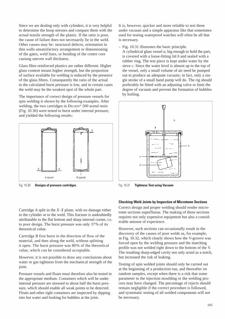
If, for example, the angles of the two profiles do notmatch (Fig. 10.29), the result will be a very sharp notchwhich can lead to stress concentrations under heavy loads,thus reducing the strength of the entire part. It also meansthat too much material has to be melted away.
104
Fig. 10.29 Joint with bad angles
The essential criteria for weld quality are the mechanicalstrength and water-tightness or air-tightness, or both. The following methods are available for testing:
a) Visual inspection of welds has a very limited applica-tion and gives no information about strength or tight-ness. It can only be carried out when the flash is actu-ally visible, i.e. not contained in a flash trap. When welding conditions are correct, a small quantityof flash should form all round the weld. If it is irregularor excessive, or even absent altogether, the speed shouldbe adjusted. Naturally, only as much plastic should be melted as is absolutely necessary. But if no flash is visible at all, there is no guarantee that the joint hasbeen properly welded (always assuming, of course,that there is no flash trap).
The appearance of the flash depends not only on thetype of plastic but also on its viscosity and on anyfillers. For example, DELRIN® 100 produces rather afibrous melt, while DELRIN® 500 gives a molten weldflash. The peripheral speed also affects the appearance,so it is not possible to draw any conclusions about thequality of the joint.
b) Testing the strength of the welds to destruction is theonly way to evaluate the weld quality properly and to be able to draw valid conclusions.
Most of the articles joined by spin welding are closedcontainers which will be under short-term or long-termpressure from the inside (lighters, gas cartridges, fireextinguishers) or from the outside (deep-water buoys).There are also, for example, carburettor floats, whichare not under stress, and for which the joint only needsto be tight. For all these parts, regardless of the actualstresses occurring in practice, it is best as well as easiestto increase the internal pressure slowly and continuouslyuntil they burst. A device of this kind, described lateron, should enable the parts to be observed while thepressure is increasing, and the deformations which takeplace before bursting very often afford valuable infor-mation about any design faults resulting in weak points.
After the burst test, the entire part (but particularly thewelded joint) should be examined thoroughly. If theweld profiles have been correctly dimensioned and the joint properly made, the weld faces should not bevisible anywhere. Fracture should occur right acrossthe weld, or along it. In the latter case, it is not possibleto conclude whether or not the weld has been the directcause of the fracture. This may have been the casewhen there is a severe notch effect as, for example, in Fig. 10.29.
For parts which are permanently under internal pressureduring service, and are also exposed to temperaturefluctuations, the burst pressure must be eight to tentimes the working pressure. This is the only guaranteethat the part will behave according to expectation dur-ing the whole of its service life (butane gas lighters,for instance).
105
Since we are dealing only with cylinders, it is very helpfulto determine the hoop stresses and compare them with theactual tensile strength of the plastic. If the ratio is poor,the cause of failure does not necessarily lie in the weld.Other causes may be: structural defects, orientation inthin walls unsatisfactory arrangement or dimensioning of the gates, weld lines, or bending of the centre corecausing uneven wall thickness.
Glass fibre reinforced plastics are rather different. Higherglass content means higher strength, but the proportion of surface available for welding is reduced by the presenceof the glass fibres. Consequently the ratio of the actual to the calculated burst pressure is low, and in certain casesthe weld may be the weakest spot of the whole part.
The importance of correct design of pressure vessels forspin welding is shown by the following examples. Afterwelding, the two cartridges in DELRIN® 500 acetal resin(Fig. 10.30) were tested to burst under internal pressure,and yielded the following results:
Cartridge A split in the X–X plane, with no damage eitherto the cylinder or to the weld. This fracture is undoubtedlyattributable to the flat bottom and sharp internal corner, i.e.to poor design. The burst pressure was only 37% of itstheoretical value.
Cartridge B first burst in the direction of flow of thematerial, and then along the weld, without splitting it open. The burst pressure was 80% of the theoreticalvalue, which can be considered acceptable.
However, it is not possible to draw any conclusions aboutwater or gas tightness from the mechanical strength of thejoint.
Pressure vessels and floats must therefore also be tested inthe appropriate medium. Containers which will be underinternal pressure are stressed to about half the burst pres-sure, which should enable all weak points to be detected.Floats and other tight containers are inspected by dippinginto hot water and looking for bubbles at the joint.
A (poor) B (good)
X X
X
Fig. 10.30 Designs of pressure cartridges
It is, however, quicker and more reliable to test themunder vacuum and a simple apparatus like that sometimesused for testing waterproof watches will often be all thatis necessary.
– Fig. 10.31 illustrates the basic principle.A cylindrical glass vessel a, big enough to hold the part,is covered with a loose-fitting lid b and sealed with arubber ring. The test piece is kept under water by thesieve c. Since the water level is almost up to the top ofthe vessel, only a small volume of air need be pumpedout to produce an adequate vacuum; in fact, only a sin-gle stroke of a small hand pump will do. The rig shouldpreferably be fitted with an adjusting valve to limit thedegree of vacuum and prevent the formation of bubblesby boiling.
Checking Weld Joints by Inspection of Microtome SectionsCorrect design and proper welding should render micro-tome sections superfluous. The making of these sectionsrequires not only expensive equipment but also a consid-erable amount of experience.
However, such sections can occasionally result in the discovery of the causes of poor welds as, for example, in Fig. 10.32, which clearly shows how the V-groove wasforced open by the welding pressure and the matchingprofile was not welded right down to the bottom of the V.The resulting sharp-edged cavity not only acted as a notch,but increased the risk of leaking.
Testing of spin welded joints should only be carried out at the beginning of a production run, and thereafter onrandom samples, except when there is a risk that someparameter in the injection moulding or the welding pro-cess may have changed. The percentage of rejects shouldremain negligible if the correct procedure is followed, and systematic testing of all welded components will notbe necessary.
a
b
c
d
Fig. 10.31 Tightness Test using Vacuum

Welding Double JointsThe simultaneous welding of two joints, e.g. in the carbu-rettor float in Fig. 10.33, requires special processes andgreater care. Practical experience has shown that it is impossible to get good results if the two halves are grippedand driven by tooth crowns. Recesses or ribs must alwaysbe provided. It is best if the machine has facilities foradjusting the respective heights of the inner and outer jigfaces, so that the weld pressure can be distributed overboth joints as required.
In these cases the moment of inertia and the welding pressure must be calculated for the sum of the surfaces. The speed, on the other hand, should be chosen as a function of the smaller diameter.
Fig. 10.33 shows a double-joint float, with appropriatejigs and small ribs for driving the parts. After welding,the spindle does not travel all the way up, so that the nextpart can be inserted into the jig at rest; only then is theflyweight engaged and accelerated to its operating speed.
The dimensions of the plastic parts should preferably besuch that the inner joint begins to weld first, i.e. whenthere is still an air-gap of about 0,2–0,3 mm on the outerjoint (Fig. 10.34).
Welding double joints becomes more difficult as the ratioof the two diameters increases. Although, in practice, partswith an external diameter of 50 mm and an internal dia-meter of 10 mm have been joined, these are exceptions.
Designs like this should only be undertaken with verygreat care and after expert advice.
Fig. 10.32 Microtome of badly welded V-groove
106
Fig. 10.35 Double joint split-up in 2 single joints
Fig. 10.34 Design of double joints
Fig. 10.33 Welding Double Joints

In order to avoid all risks, it is better to follow the proce-dure shown in Fig. 10.35. Here the double joint has beendivided into two single ones, which can be welded oneafter the other and which pose no problem. This solutionenables the parts to be gripped with tooth crowns in thenormal way, automation is easier, and the total cost isvery little more than for one double joint, while avoidinglong-winded and expensive preliminary testing.
Welding Reinforced and Dissimilar PlasticsReinforced plastics can generally be welded just as easilyas unreinforced ones. If the filler reduces the coefficientof friction, the weld pressure may sometimes have to beincreased so as to reduce the effective weld time.
The weld strength of reinforced plastics is generally lowerbecause the fibres on the surface do not weld together. Thisis not usually evident in practice, because the joint is notusually the weakest part. If necessary, the weld profilecan be enlarged somewhat. In all plastics, glass fibres or fillers reduce tensile elongation, so that stress concen-trations are very harmful. Designers pay far too littleattention to this fact.
Occasionally one is also faced with the problem of joiningplastics of different types, with different melting points.The greater the difference between the melting points, themore difficult welding will be, and one cannot call such a joint a true weld, as it is merely a mechanical adhesionof the surfaces. The strength of the joint will be low. It mayeven be necessary to have special joint profiles and workwith very high weld pressures.
In practice there are very few such applications, and in allthese cases the parts are not subjected to stresses. Typicalapplications are oil-level gauges and transparent polycar-bonate spy-holes welded into holders of DELRIN®.
The following test results should give some idea of thepossibilities of joining DELRIN® to other plastics.
The float of DELRIN® shown in Fig. 10.13 has a burst pressure of about 4 MPa. If a cap of some other materialis welded onto a body of DELRIN®, the burst pressures areas follows:
ZYTEL® 101 (nylon resin) 0,15–0,7 MPa
Polycarbonate 1,2 –1,9 MPa
Acrylic resin 2,2 –2,4 MPa
ABS 1,2 –1,6 MPa
It must be remembered that, in all these cases, the weldforms the weakest point.
Spin Welding Soft Plastics and ElastomersThe softer the plastic, with a few exceptions (e.g. fluoro-polymers), the higher the coefficient of friction. Spinwelding therefore becomes increasingly difficult with soft plastics, for the following three reasons:
a) The deceleration produced by a high coefficient offriction is so great that the flyweight is unable to pro-duce heat by friction. Much of the energy is absorbedin the deformation of the component, without anyrelative motion occurring between the joint faces. Ifthe amount of kinetic energy is increased, one is morelikely to damage the parts than to improve weldingconditions.
It is sometimes possible to solve this problem by spray-ing a lubricant onto the joint faces (e.g. a silicone mouldrelease). This reduces the coefficient of friction veryconsiderably at first, so that the usual rotation takesplace. The specific pressure is, however, so high thatthe lubricant is rapidly squeezed out, the frictionincreases, and the material melts.
b) For soft plastics having a very low coefficient of fric-tion a very much higher specific pressure is needed to produce sufficient heat by friction in a short time.Most components cannot stand such a high axial pres-sure without being permanently deformed, and there is to date no reliable way of making satisfactory jointsbetween these materials by spin welding.
c) Soft plastic parts are difficult to retain and cannot easily be driven. Transmission of the high torque frequently poses an insoluble problem, particularlysince it is scarcely possible to use tooth crowns.
To sum up, it can be said that marginal cases of this sortshould be approached only with extreme caution, and thatpreliminary experimental work is unavoidable.
Figures 10.36–10.38 show only a few selected examplesout of the great number of possibilities in this field.
107

Examples of Commercial and Experimental Mecasonic Spin Machines
108
Fig. 10.36 Commercial mecasonic spin machine.
109
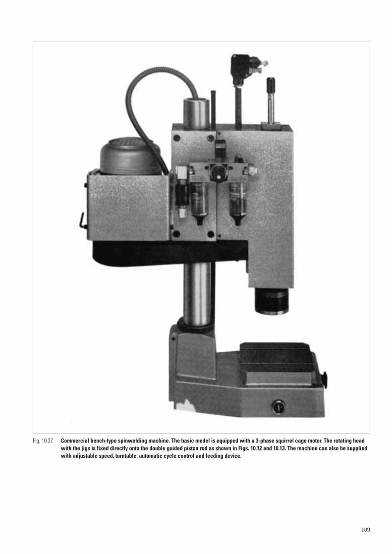
Fig. 10.37 Commercial bench-type spinwelding machine. The basic model is equipped with a 3-phase squirrel cage motor. The rotating headwith the jigs is fixed directly onto the double guided piston rod as shown in Figs. 10.12 and 10.13. The machine can also be suppliedwith adjustable speed, turntable, automatic cycle control and feeding device.

110
Fig. 10.38 Spinwelding machine.
Ultrasonic Welding
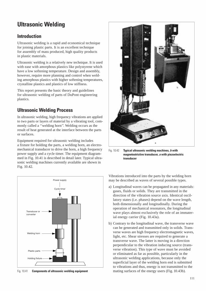
IntroductionUltrasonic welding is a rapid and economical techniquefor joining plastic parts. It is an excellent technique for assembly of mass produced, high quality products in plastic materials.
Ultrasonic welding is a relatively new technique. It is usedwith ease with amorphous plastics like polystyrene whichhave a low softening temperature. Design and assembly,however, require more planning and control when weld-ing amorphous plastics with higher softening temperatures,crystalline plastics and plastics of low stiffness.
This report presents the basic theory and guidelines for ultrasonic welding of parts of DuPont engineeringplastics.
Ultrasonic Welding ProcessIn ultrasonic welding, high frequency vibrations are appliedto two parts or layers of material by a vibrating tool, com-monly called a ‘‘welding horn’’. Welding occurs as theresult of heat generated at the interface between the partsor surfaces.
Equipment required for ultrasonic welding includes a fixture for holding the parts, a welding horn, an electro-mechanical transducer to drive the horn, a high frequencypower supply and a cycle timer. The equipment diagram-med in Fig. 10.41 is described in detail later. Typical ultra-sonic welding machines currently available are shown inFig. 10.42.
Power supply
Cycle timer
Transducer orconverter
Welding horn
Plastic parts
Holding fixture
Fig. 10.41 Components of ultrasonic welding equipment
Vibrations introduced into the parts by the welding hornmay be described as waves of several possible types.
a) Longitudinal waves can be propagated in any materials:gases, fluids or solids. They are transmitted in thedirection of the vibration source axis. Identical oscil-latory states (i.e. phases) depend on the wave length,both dimensionally and longitudinally. During theoperation of mechanical resonators, the longitudinalwave plays almost exclusively the role of an immater-ial energy carrier (Fig. 10.43a).
b) Contrary to the longitudinal wave, the transverse wavecan be generated and transmitted only in solids. Trans-verse waves are high frequency electromagnetic waves,light, etc. Shear stresses are required to generate atransverse wave. The latter is moving in a directionperpendicular to the vibration inducing source (trans-verse vibration). This type of wave must be avoided or eliminated as far as possible, particularly in theultrasonic welding applications, because only thesuperficial layer of the welding horn end is submittedto vibrations and thus, energy is not transmitted to themating surfaces of the energy users (Fig. 10.43b).
111
a
b
Fig. 10.42 Typical ultrasonic welding machines, b withmagnetostrictive transducer, a with piezoelectrictransducer
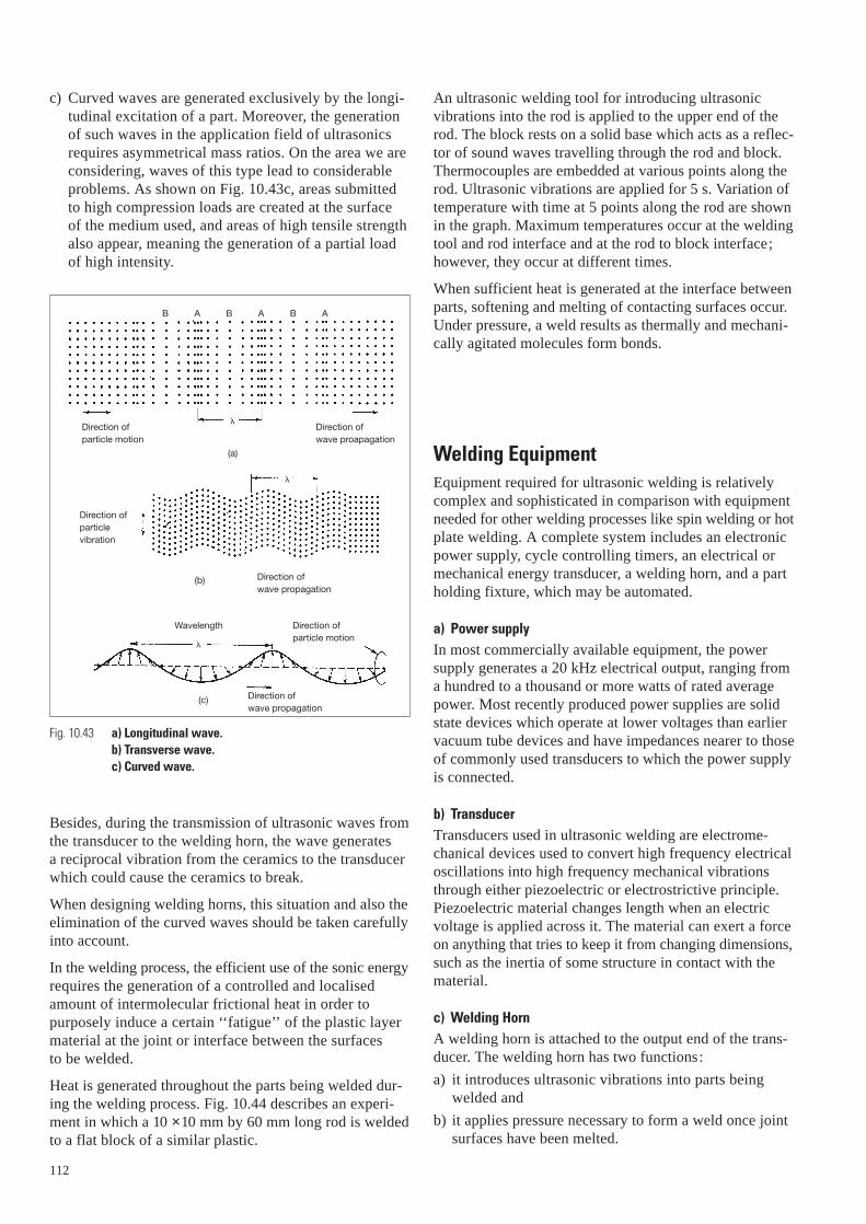
c) Curved waves are generated exclusively by the longi-tudinal excitation of a part. Moreover, the generation of such waves in the application field of ultrasonicsrequires asymmetrical mass ratios. On the area we areconsidering, waves of this type lead to considerableproblems. As shown on Fig. 10.43c, areas submitted to high compression loads are created at the surface of the medium used, and areas of high tensile strengthalso appear, meaning the generation of a partial load of high intensity.
Besides, during the transmission of ultrasonic waves fromthe transducer to the welding horn, the wave generates a reciprocal vibration from the ceramics to the transducerwhich could cause the ceramics to break.
When designing welding horns, this situation and also theelimination of the curved waves should be taken carefullyinto account.
In the welding process, the efficient use of the sonic energyrequires the generation of a controlled and localisedamount of intermolecular frictional heat in order to purposely induce a certain ‘‘fatigue’’ of the plastic layermaterial at the joint or interface between the surfaces to be welded.
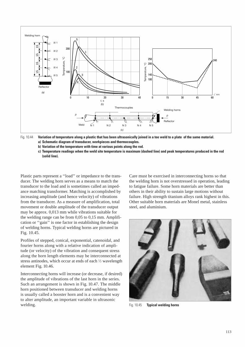
Heat is generated throughout the parts being welded dur-ing the welding process. Fig. 10.44 describes an experi-ment in which a 10 ×10 mm by 60 mm long rod is weldedto a flat block of a similar plastic.
112
B A B A B A
Direction ofparticle motion
Direction of wave proapagation
(a)
�
�
�
Direction ofparticlevibration
Direction of wave propagation
Direction of wave propagation
(b)
(c)
Wavelength Direction ofparticle motion
Fig. 10.43 a) Longitudinal wave. b) Transverse wave. c) Curved wave.
An ultrasonic welding tool for introducing ultrasonicvibrations into the rod is applied to the upper end of therod. The block rests on a solid base which acts as a reflec-tor of sound waves travelling through the rod and block.Thermocouples are embedded at various points along therod. Ultrasonic vibrations are applied for 5 s. Variation oftemperature with time at 5 points along the rod are shownin the graph. Maximum temperatures occur at the weldingtool and rod interface and at the rod to block interface;however, they occur at different times.
When sufficient heat is generated at the interface betweenparts, softening and melting of contacting surfaces occur.Under pressure, a weld results as thermally and mechani-cally agitated molecules form bonds.
Welding EquipmentEquipment required for ultrasonic welding is relativelycomplex and sophisticated in comparison with equipmentneeded for other welding processes like spin welding or hotplate welding. A complete system includes an electronicpower supply, cycle controlling timers, an electrical ormechanical energy transducer, a welding horn, and a partholding fixture, which may be automated.
a) Power supplyIn most commercially available equipment, the powersupply generates a 20 kHz electrical output, ranging froma hundred to a thousand or more watts of rated averagepower. Most recently produced power supplies are solidstate devices which operate at lower voltages than earliervacuum tube devices and have impedances nearer to thoseof commonly used transducers to which the power supplyis connected.
b) TransducerTransducers used in ultrasonic welding are electrome-chanical devices used to convert high frequency electricaloscillations into high frequency mechanical vibrationsthrough either piezoelectric or electrostrictive principle.Piezoelectric material changes length when an electricvoltage is applied across it. The material can exert a forceon anything that tries to keep it from changing dimensions,such as the inertia of some structure in contact with thematerial.
c) Welding HornA welding horn is attached to the output end of the trans-ducer. The welding horn has two functions:
a) it introduces ultrasonic vibrations into parts beingwelded and
b) it applies pressure necessary to form a weld once jointsurfaces have been melted.
20100
5
1
2
3
4
1515
1515
30 40 0 15 30 45 60
100140
100
240200
250
200
Tem
pera
ture
, °C
Tem
pera
ture
, °C
Welding horn
Reflector
(a)
N 1
N 2
N 3
N 4
N 5
t, s(b)
Welding horns
Reflector
p
Thermocouples
N 1 N 2 N 3 N 4 N 5
(c)
Weld
p
Fig. 10.44 Variation of temperature along a plastic that has been ultrasonically joined in a tee weld to a plate of the same material. a) Schematic diagram of transducer, workpieces and thermocouples. b) Variation of the temperature with time at various points along the rod. c) Temperature readings when the weld site temperature is maximum (dashed line) and peak temperatures produced in the rod
(solid line).
Tem
per
atur
e, °
C
Tem
per
atur
e, °
C
l, mm
Plastic parts represent a ‘‘load’’ or impedance to the trans-ducer. The welding horn serves as a means to match thetransducer to the load and is sometimes called an imped-ance matching transformer. Matching is accomplished byincreasing amplitude (and hence velocity) of vibrationsfrom the transducer. As a measure of amplification, totalmovement or double amplitude of the transducer outputmay be approx. 0,013 mm while vibrations suitable forthe welding range can be from 0,05 to 0,15 mm. Amplifi-cation or ‘‘gain’’ is one factor in establishing the designof welding horns. Typical welding horns are pictured inFig. 10.45.
Profiles of stepped, conical, exponential, catenoidal, andfourier horns along with a relative indication of ampli-tude (or velocity) of the vibration and consequent stressalong the horn length elements may be interconnected atstress antinodes, which occur at ends of each 1⁄2 wavelengthelement Fig. 10.46.
Interconnecting horns will increase (or decrease, if desired)the amplitude of vibrations of the last horn in the series.Such an arrangement is shown in Fig. 10.47. The middlehorn positioned between transducer and welding horns is usually called a booster horn and is a convenient way to alter amplitude, an important variable in ultrasonic welding.
Care must be exercised in interconnecting horns so thatthe welding horn is not overstressed in operation, leadingto fatigue failure. Some horn materials are better than others in their ability to sustain large motions withoutfailure. High strength titanium alloys rank highest in this.Other suitable horn materials are Monel metal, stainlesssteel, and aluminium.
Fig. 10.45 Typical welding horns
113

Horn material must not dissipate acoustic energy. Copper,lead, nickel, and cast iron are not suitable horn materials.Horn designs described in Fig. 10.46 are suitable for weld-ing only small pieces in DuPont engineering plastics.
In materials like polystyrene, parts with an overall sizelarger than the end area of a welding horn can be weldedwith ‘‘spot’’ horns, shown in Fig. 10.45.
For welding off parts of DuPont engineering plastics,larger than 25 mm in diameter, the horn end plan shouldfollow joint layout. Bar and hollow horns, also shown inFig. 10.47, are useful for welding larger rectangular andcircular pieces respectively.
114
TransducerAssembly
Booster horn
Weldinghorn
A
N
A
N
A
A
A
0
50
100
150
200
250
300
350
400
Leng
th (m
m)
25 �m
700 bars
0
�
25 �m
700 bars�
�
Profile
Velocity
Stress
Profile
Velocity
Stress
Profile
VelocityStress
Profile
VelocityStress
Profile
Velocity
Stress
Fig. 10.46 The profiles of horns for amplifying the output oftransducers are as follows: a) Stepped. b) Conical. c) Exponential. d) Catenoidal. e) Fourier. The variations in particles velocity and stress along he horns are shown below each profile.
Fig. 10.47 Tapered or stepped horns may be cascaded to provideincreased amplification. The step discontinuities are atantinodal junctions. Measured values of the amplitudeand stress at various points along the system are shown.Displacement nodes and antinodes are shown at N and Arespectively.
a)
b)
d)
e)
c)
Further details of this important relationship between partdesign and horn design are discussed in greater detailunder Part Design.
The width or diameter of bar or hollow horns is restrictedin many cases to a dimension not greater than 1⁄4 the wave-length of the sound in the horn material. As a lateraldimension of the horn exceeds this nominal limitation,lateral modes of vibration in the horn are excited. Thehorn’s efficiency is thereby reduced. For titanium hornsusing standard design configurations, lateral dimensionsof 65 to 75 mm are limiting. Larger horns may be con-structed with slots interrupting lateral dimensions exceed-ing 1⁄4 the wavelength.
Large parts can also be welded with several clustered horns.With one technique, the horns, each with a transducer, areenergized simultaneously from individual power suppliesor sequentially energized from one power supply. Anothertechnique utilizes a cluster of horns attached to a singletransducer which, when cycled, energizes the hornssimultaneously.
For efficient welding, horns must resonate at a frequencyvery near the nominal 20 kHz operating frequency of thewelding system. Thus, welding equipment manufacturerselectronically tune welding horns, making subtle variationsin horn dimensions to achieve optimum performance.While simple step horns in aluminium may be readilymade in the laboratory for the purpose of evaluating pro-totype welds, such horns are subject to fatigue failure, arereadily nicked and damaged, and frequently mark partsbeing welded. Thus, design and fabrication of more com-plex horns and horns using more sophisticated materialsshould be left to equipment manufacturers with experienceand capabilities in analytical and empirical design ofwelding horns.
d) Holding FixtureFixtures for aligning parts and holding them stationaryduring welding are an important aspect of the weldingequipment. Parts must be held in alignment with respectto the end of the horn so that uniform pressure betweenparts is maintained during welding. If the bottom part ofthe two parts to be welded is simply placed on the weldertable, both parts may slide out from under the horn duringwelding. High frequency vibrations reduce the effect ofnominal frictional forces which might otherwise holdpieces stationary. A typical fixture is shown in Fig. 10.48.
Most frequently used fixtures are machined or cast so thatthe fixture engages the lower part and holds it securely inthe desired position. The question of whether a part mustbe held virtually immovable during welding has not beenresolved to date through suitable, controlled experiments.Welding success has been observed in cases where partswere restrained but free to vibrate and when parts wererigidly clamped.
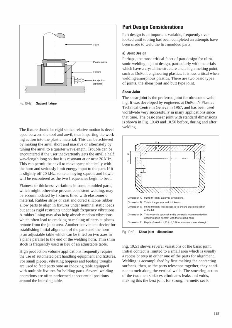
The fixture should be rigid so that relative motion is devel-oped between the tool and anvil, thus imparting the work-ing action into the plastic material. This can be achievedby making the anvil short and massive or alternately bytuning the anvil to a quarter wavelength. Trouble can beencountered if the user inadvertently gets the anvil a halfwavelength long so that it is resonant at or near 20 kHz.This can permit the anvil to move sympathetically withthe horn and seriously limit energy input to the part. If itis slightly off 20 kHz, some annoying squeals and howlswill be encoutered as the two frequencies begin to beat.
Flatness or thickness variations in some moulded parts,which might otherwise prevent consistent welding, maybe accommodated by fixtures lined with elastomericmaterial. Rubber strips or cast and cured silicone rubberallow parts to align in fixtures under nominal static loadsbut act as rigid restraints under high frequency vibrations.A rubber lining may also help absorb random vibrationswhich often lead to cracking or melting of parts at placesremote from the joint area. Another convenient device forestablishing initial alignment of the parts and the horn is an adjustable table which can be tilted on two axes in a plane parallel to the end of the welding horn. Thin shimstock is frequently used in lieu of an adjustable table.
High production volume applications frequently requirethe use of automated part handling equipment and fixtures.For small pieces, vibrating hoppers and feeding troughsare used to feed parts onto an indexing table equippedwith multiple fixtures for holding parts. Several weldingoperations are often performed at sequential positionsaround the indexing table.
Horn
Plastic parts
Fixture
Air ejection(optional)
Fig. 10.48 Support fixture
Part Design ConsiderationsPart design is an important variable, frequently over-looked until tooling has been completed an attempts havebeen made to weld the firt moulded parts.
a) Joint DesignPerhaps, the most critical facet of part design for ultra-sonic welding is joint design, particularly with materialswhich have a crystalline structure and a high melting point,such as DuPont engineering plastics. It is less critical whenwelding amorphous plastics. There are two basic types of joints, the shear joint and butt type joint.
Shear JointThe shear joint is the preferred joint for ultrasonic weld-ing. It was developed by engineers at DuPont’s PlasticsTechnical Centre in Geneva in 1967, and has been usedworldwide very successfully in many applications sincethat time. The basic shear joint with standard dimensionsis shown in Fig. 10.49 and 10.50 before, during and afterwelding.
Fig. 10.51 shows several variations of the basic joint. Initial contact is limited to a small area which is usually a recess or step in either one of the parts for alignment.Welding is accomplished by first melting the contactingsurfaces; then, as the parts telescope together, they conti-nue to melt along the vertical walls. The smearing actionof the two melt surfaces eliminates leaks and voids, making this the best joint for strong, hermetic seals.
A
B
B
CE
BD
Dimension A 0,2 to 0,4 mm. External dimensions.
Dimension B This is the general wall thickness.
Dimension C 0,5 to 0,8 mm. This recess is to ensure precise location of the lid.
Dimension D This recess is optional and is generally recommended forensuring good contact with the welding horn.
Dimension E Depth of weld = 1,25 to 1,5 B for maximum joint strength.
Fig. 10.49 Shear joint – dimensions
115
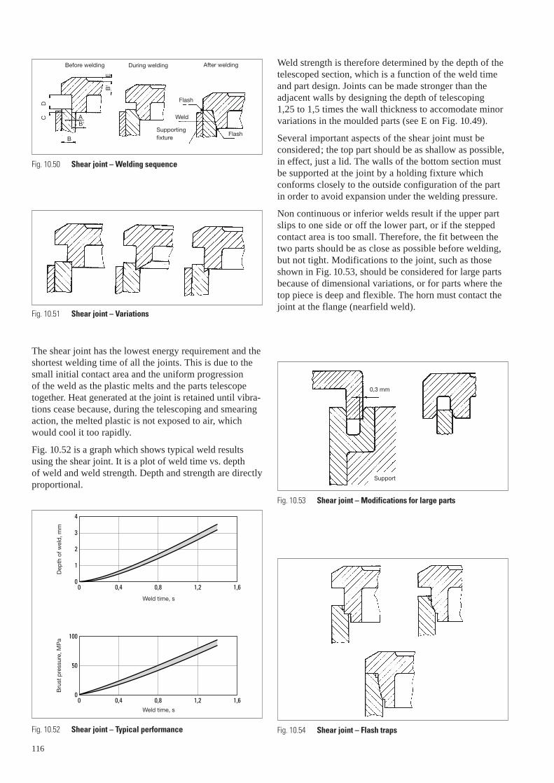
The shear joint has the lowest energy requirement and theshortest welding time of all the joints. This is due to thesmall initial contact area and the uniform progression of the weld as the plastic melts and the parts telescopetogether. Heat generated at the joint is retained until vibra-tions cease because, during the telescoping and smearingaction, the melted plastic is not exposed to air, whichwould cool it too rapidly.
Fig. 10.52 is a graph which shows typical weld resultsusing the shear joint. It is a plot of weld time vs. depth of weld and weld strength. Depth and strength are directlyproportional.
Before welding During welding After welding
Flash
Weld
FlashSupportingfixture
C
D
AB1
B
B1
E
Fig. 10.50 Shear joint – Welding sequence
Fig. 10.51 Shear joint – Variations
Fig. 10.52 Shear joint – Typical performance
0,80 0,4 1,2 1,6
0,80 0,4 1,2 1,6
1
0
2
3
4
50
100
0
Weld time, s
Dep
th o
f wel
d, m
m
Weld time, s
Bru
st p
ress
ure,
MP
aB
rust
pre
ssur
e, M
Pa
Dep
th o
f wel
d, m
m
Weld time, s
Weld time, s
116
Weld strength is therefore determined by the depth of thetelescoped section, which is a function of the weld timeand part design. Joints can be made stronger than theadjacent walls by designing the depth of telescoping 1,25 to 1,5 times the wall thickness to accomodate minorvariations in the moulded parts (see E on Fig. 10.49).
Several important aspects of the shear joint must be considered; the top part should be as shallow as possible,in effect, just a lid. The walls of the bottom section mustbe supported at the joint by a holding fixture which conforms closely to the outside configuration of the partin order to avoid expansion under the welding pressure.
Non continuous or inferior welds result if the upper partslips to one side or off the lower part, or if the steppedcontact area is too small. Therefore, the fit between thetwo parts should be as close as possible before welding,but not tight. Modifications to the joint, such as thoseshown in Fig. 10.53, should be considered for large partsbecause of dimensional variations, or for parts where thetop piece is deep and flexible. The horn must contact thejoint at the flange (nearfield weld).
Fig. 10.53 Shear joint – Modifications for large parts
Fig. 10.54 Shear joint – Flash traps
0,3 mm
Support
Allowance should be made in the design of the joint forthe flow of molten material displaced during welding.When flash cannot be tolerated for aesthetic or functionalreasons, a trap similar to the ones shown in Fig. 10.54 canbe designed into the joint.
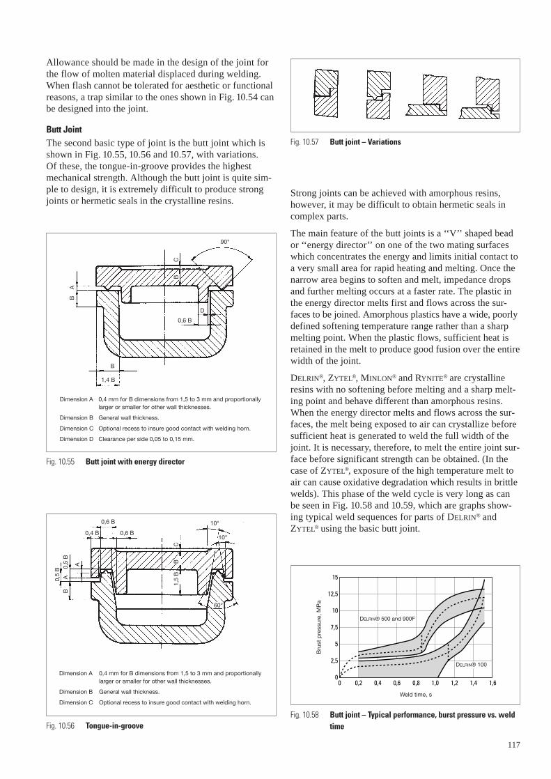
Butt JointThe second basic type of joint is the butt joint which isshown in Fig. 10.55, 10.56 and 10.57, with variations. Of these, the tongue-in-groove provides the highestmechanical strength. Although the butt joint is quite sim-ple to design, it is extremely difficult to produce strongjoints or hermetic seals in the crystalline resins.
Dimension A 0,4 mm for B dimensions from 1,5 to 3 mm and proportionally larger or smaller for other wall thicknesses.
Dimension B General wall thickness.
Dimension C Optional recess to insure good contact with welding horn.
Dimension D Clearance per side 0,05 to 0,15 mm.
Dimension A 0,4 mm for B dimensions from 1,5 to 3 mm and proportionally larger or smaller for other wall thicknesses.
Dimension B General wall thickness.
Dimension C Optional recess to insure good contact with welding horn.
60°
10°
10°
0,6 B
0,6 B0,4 B
1,5
B
B
C
A
0,5
BB
A
0,5
B
90°
D
0,6 B
B
1,4 B
B
A
B
C
Fig. 10.55 Butt joint with energy director
Fig. 10.56 Tongue-in-groove
Strong joints can be achieved with amorphous resins,however, it may be difficult to obtain hermetic seals incomplex parts.
The main feature of the butt joints is a ‘‘V’’ shaped beador ‘‘energy director’’ on one of the two mating surfaceswhich concentrates the energy and limits initial contact toa very small area for rapid heating and melting. Once thenarrow area begins to soften and melt, impedance dropsand further melting occurs at a faster rate. The plastic inthe energy director melts first and flows across the sur-faces to be joined. Amorphous plastics have a wide, poorlydefined softening temperature range rather than a sharpmelting point. When the plastic flows, sufficient heat isretained in the melt to produce good fusion over the entirewidth of the joint.
DELRIN®, ZYTEL®, MINLON® and RYNITE® are crystallineresins with no softening before melting and a sharp melt-ing point and behave different than amorphous resins.When the energy director melts and flows across the sur-faces, the melt being exposed to air can crystallize beforesufficient heat is generated to weld the full width of thejoint. It is necessary, therefore, to melt the entire joint sur-face before significant strength can be obtained. (In thecase of ZYTEL®, exposure of the high temperature melt toair can cause oxidative degradation which results in brittlewelds). This phase of the weld cycle is very long as canbe seen in Fig. 10.58 and 10.59, which are graphs show-ing typical weld sequences for parts of DELRIN® andZYTEL® using the basic butt joint.
117
Fig. 10.57 Butt joint – Variations
Fig. 10.58 Butt joint – Typical performance, burst pressure vs. weldtime
0 0,40,2 0,80,6 1,21,0 1,61,4
7,5
10
12,5
15
5
2,5
0
Weld time, s
Bru
st p
ress
ure,
MP
a
DELRIN® 500 and 900F
DELRIN® 100
Weld time, s
Bru
st p
ress
ure,
MP
a
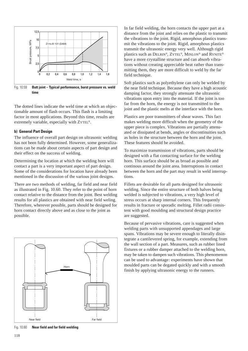
The dotted lines indicate the weld time at which an objec-tionable amount of flash occurs. This flash is a limitingfactor in most applications. Beyond this time, results areextremely variable, especially with ZYTEL®.
b) General Part DesignThe influence of overall part design on ultrasonic weldinghas not been fully determined. However, some generaliza-tions can be made about certain aspects of part design andtheir effect on the success of welding.
Determining the location at which the welding horn willcontact a part is a very important aspect of part design.Some of the considerations for location have already beenmentioned in the discussion of the various joint designs.
There are two methods of welding, far field and near fieldas illustrated in Fig. 10.60. They refer to the point of horncontact relative to the distance from the joint. Best weldingresults for all plastics are obtained with near field weling.Therefore, wherever possible, parts should be designed forhorn contact directly above and as close to the joint aspossible.
Fig. 10.59 Butt joint – Typical performance, burst pressure vs. weldtime
0 0,2 0,4 0,6 0,8 1,0 1,2 1,4 1,6
2,5
0
7,5
5
10
12,5
Weld time, s
Bru
st p
ress
ure,
MP
a
ZYTEL® 101 (DAM)
Horn
Near field Far field
Fig. 10.60 Near field and far field welding
Weld time, s
Bru
st p
ress
ure,
MP
a
118
In far field welding, the horn contacts the upper part at adistance from the joint and relies on the plastic to transmitthe vibrations to the joint. Rigid, amorphous plastics trans-mit the vibrations to the joint. Rigid, amorphous plasticstransmit the ultrasonic energy very well. Although rigidplastics such as DELRIN®, ZYTEL®, MINLON® and RYNITE®
have a more crystalline structure and can absorb vibra-tions without creating appreciable heat rather than trans-mitting them, they are more difficult to weld by the farfield technique.
Soft plastics such as polyethylene can only be welded bythe near field technique. Because they have a high acousticdamping factor, they strongly attenuate the ultrasonicvibrations upon entry into the material. If the joint is toofar from the horn, the energy is not transmitted to thejoint and the plastic melts at the interface with the horn.
Plastics are poor transmitters of shear waves. This factmakes welding more difficult when the geometry of theupper piece is complex. Vibrations are partially attenu-ated or dissipated at bends, angles or discontinuities suchas holes in the structure between the horn and the joint.These features should be avoided.
To maximize transmission of vibrations, parts should bedesigned with a flat contacting surface for the weldinghorn. This surface should be as broad as possible and continous around the joint area. Interruptions in contactbetween the horn and the part may result in weld interrup-tions.
Fillets are desirable for all parts designed for ultrasonicwelding. Since the entire structure of both halves beingwelded is subjected to vibrations, a very high level ofstress occurs at sharp internal corners. This frequentlyresults in fracture or sporadic melting. Fillet radii consis-tent with good moulding and structural design practiceare suggested.
Because of pervasive vibrations, care is suggested whenwelding parts with unsupported appendages and largespans. Vibrations may be severe enough to literally disin-tegrate a cantilevered spring, for example, extending fromthe wall section of a part. Measures, such as rubber linedfixtures or a rubber damper attached to the welding horn,may be taken to dampen such vibrations. This phenomenoncan be used to advantage: experiments have shown thatmoulded parts can be degated quickly and with a smoothfinish by applying ultrasonic energy to the runners.
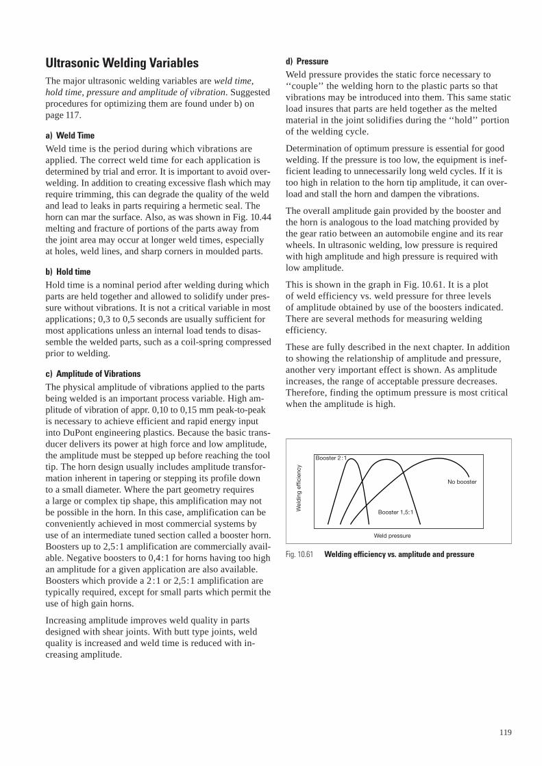
Ultrasonic Welding VariablesThe major ultrasonic welding variables are weld time,hold time, pressure and amplitude of vibration. Suggestedprocedures for optimizing them are found under b) onpage 117.
a) Weld TimeWeld time is the period during which vibrations areapplied. The correct weld time for each application isdetermined by trial and error. It is important to avoid over-welding. In addition to creating excessive flash which mayrequire trimming, this can degrade the quality of the weldand lead to leaks in parts requiring a hermetic seal. Thehorn can mar the surface. Also, as was shown in Fig. 10.44melting and fracture of portions of the parts away fromthe joint area may occur at longer weld times, especiallyat holes, weld lines, and sharp corners in moulded parts.
b) Hold timeHold time is a nominal period after welding during whichparts are held together and allowed to solidify under pres-sure without vibrations. It is not a critical variable in mostapplications; 0,3 to 0,5 seconds are usually sufficient formost applications unless an internal load tends to disas-semble the welded parts, such as a coil-spring compressedprior to welding.
c) Amplitude of VibrationsThe physical amplitude of vibrations applied to the partsbeing welded is an important process variable. High am-plitude of vibration of appr. 0,10 to 0,15 mm peak-to-peakis necessary to achieve efficient and rapid energy inputinto DuPont engineering plastics. Because the basic trans-ducer delivers its power at high force and low amplitude,the amplitude must be stepped up before reaching the tooltip. The horn design usually includes amplitude transfor-mation inherent in tapering or stepping its profile down to a small diameter. Where the part geometry requires a large or complex tip shape, this amplification may notbe possible in the horn. In this case, amplification can beconveniently achieved in most commercial systems byuse of an intermediate tuned section called a booster horn.Boosters up to 2,5:1 amplification are commercially avail-able. Negative boosters to 0,4:1 for horns having too highan amplitude for a given application are also available.Boosters which provide a 2 :1 or 2,5:1 amplification aretypically required, except for small parts which permit theuse of high gain horns.
Increasing amplitude improves weld quality in partsdesigned with shear joints. With butt type joints, weldquality is increased and weld time is reduced with in-creasing amplitude.
d) PressureWeld pressure provides the static force necessary to‘‘couple’’ the welding horn to the plastic parts so thatvibrations may be introduced into them. This same staticload insures that parts are held together as the meltedmaterial in the joint solidifies during the ‘‘hold’’ portionof the welding cycle.
Determination of optimum pressure is essential for goodwelding. If the pressure is too low, the equipment is inef-ficient leading to unnecessarily long weld cycles. If it istoo high in relation to the horn tip amplitude, it can over-load and stall the horn and dampen the vibrations.
The overall amplitude gain provided by the booster andthe horn is analogous to the load matching provided bythe gear ratio between an automobile engine and its rearwheels. In ultrasonic welding, low pressure is requiredwith high amplitude and high pressure is required withlow amplitude.
This is shown in the graph in Fig. 10.61. It is a plot of weld efficiency vs. weld pressure for three levels of amplitude obtained by use of the boosters indicated.There are several methods for measuring welding efficiency.
These are fully described in the next chapter. In additionto showing the relationship of amplitude and pressure,another very important effect is shown. As amplitudeincreases, the range of acceptable pressure decreases.Therefore, finding the optimum pressure is most criticalwhen the amplitude is high.
Fig. 10.61 Welding efficiency vs. amplitude and pressure
Booster 2 :1
No booster
Booster 1,5:1
Weld pressure
Wel
din
g ef
ficie
ncy
119
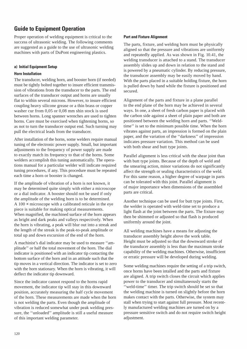
Guide to Equipment OperationProper operation of welding equipment is critical to thesuccess of ultrasonic welding. The following commentsare suggested as a guide to the use of ultrasonic weldingmachines with parts of DuPont engineering plastics.
a) Initial Equipment Setup
Horn InstallationThe transducer, welding horn, and booster horn (if needed)must be tightly bolted together to insure efficient transmis-sion of vibrations from the transducer to the parts. The endsurfaces of the transducer output and horns are usuallyflat to within several microns. However, to insure efficientcoupling heavy silicone grease or a thin brass or copperwasher cur from 0,05 or 0,08 mm shin stock is usedbetween horns. Long spanner wrenches are used to tightenhorns. Care must be exercised when tightening horns, soas not to turn the transducer output end. Such turning maypull the electrical leads from the transducer.
After installation of the horns, some welders require manualtuning of the electronic power supply. Small, but importantadjustments to the frequency of power supply are made to exactly match its frequency to that of the horns. Somewelders accomplish this tuning automatically. The opera-tions manual for a particular welder will indicate requiredtuning procedures, if any. This procedure must be repeatedeach time a horn or booster is changed.
If the amplitude of vibration of a horn is not known, itmay be determined quite simply with either a microscopeor a dial indicator. A booster should not be used if onlythe amplitude of the welding horn is to be determined. A 100 × microscope with a calibrated reticule in the eyepiece is suitable for making optical measurements. When magnified, the machined surface of the horn appearsas bright and dark peaks and valleys respectively. Whenthe horn is vibrating, a peak will blur out into a streak andthe length of the streak is the peak-to-peak amplitude ortotal up and down excursion of the end of the horn.
A machinist’s dial indicator may be used to measure ‘‘am-plitude’’ or half the total movement of the horn. The dialindicator is positioned with an indicator tip contacting thebottom surface of the horn and in an attitude such that thetip moves in a vertical direction. The indicator is set to zerowith the horn stationary. When the horn is vibrating, it willdeflect the indicator tip downward.
Since the indicator cannot respond to the horns rapidmovement, the indicator tip will stay in this downwardposition, accurately measuring the half cycle movementof the horn. These measurements are made when the hornis not welding the parts. Even though the amplitude ofvibration is reduced somewhat under peak welding pres-sure, the ‘‘unloaded’’ amplitude is still a useful measure of this important welding parameter.
120
Part and Fixture Alignment
The parts, fixture, and welding horn must be physicallyaligned so that the pressure and vibrations are uniformlyand repeatedly applied. As was shown in Fig. 10.41, thewelding transducer is attached to a stand. The transducerassembly slides up and down in relation to the stand andis powered by a pneumatic cylinder. By reducing pressure,the transducer assembly may be easily moved by hand.With the parts placed in a suitable holding fixture, the hornis pulled down by hand while the fixture is positioned andsecured.
Alignment of the parts and fixture in a plane parallel to the end plane of the horn may be achieved in severalways. In one, a sheet of fresh carbon paper is placed withthe carbon side against a sheet of plain paper and both arepositioned between the welding horn and parts. ‘‘Weld-time’’ is set to the minimum possible time. When the hornvibrates against parts, an impression is formed on the plainpaper, and the variation of the ‘‘darkness’’ of impressionindicates pressure variation. This method can be usedwith both shear and butt type joints.
Parallel alignment is less critical with the shear joint thanwith butt type joints. Because of the depth of weld andthe smearing action, minor variations do not significantlyaffect the strength or sealing characteristics of the weld.For this same reason, a higher degree of warpage in partscan be tolerated with this joint. Parallel alignment is of major importance when dimensions of the assembledparts are critical.
Another technique can be used for butt type joints. First,the welder is operated with weld-time set to produce alight flash at the joint between the parts. The fixture maythen be shimmed or adjusted so that flash is produceduniformly around the joint.
All welding machines have a means for adjusting thetransducer assembly height above the work table. Height must be adjusted so that the downward stroke ofthe transducer assembly is less than the maximum strokecapability of the welding machines. Otherwise, insufficientor erratic pressure will be developed during welding.
Some welding machines require the setting of a trip switch,once horns have been intalled and the parts and fixtureare aligned. A trip switch closes the circuit which appliespower to the transducer and simultaneously starts the‘‘weld-time’’ timer. The trip switch should be set so thatthe welding machine is turned on slightly before the hornmakes contact with the parts. Otherwise, the system maystall when trying to start against full pressure. Most recent-ly manufactured welding machines are turned on by apressure sensitive switch and do not require switch heightadjustment.
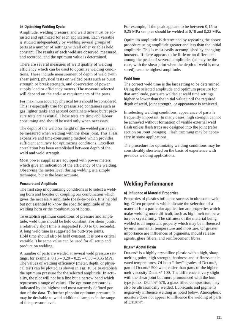
121
b) Optimizing Welding CycleAmplitude, welding pressure, and weld time must be ad-justed and optimized for each application. Each variableis studied independently by welding several groups ofparts at a number of settings with all other vriables heldconstant. The results of each weld are observed, measured,and recorded, and the optimum value is determined.
There are several measures of weld quality of weldingefficiency which can be used to optimize welding condi-tions. These include measurement of depth of weld (withshear joint), physical tests on welded parts such as burststrength or break strength, and observation of power supply load or efficiency meters. The measure selectedwill depend on the end-use requirements of the parts.
For maximum accuracy physical tests should be considered.This is especially true for pressurized containers such asgas lighter tanks and aerosol containers where burst pres-sure tests are essential. These tests are time and labourconsuming and should be used only when necessary.
The depth of the weld (or height of the welded parts) canbe measured when welding with the shear joint. This a lessexpensive and time-consuming method which providessufficient accuracy for optimizing conditions. Excellentcorrelation has been established between depth of theweld and weld strength.
Most power supplies are equipped with power meterswhich give an indication of the efficiency of the welding.Observing the meter level during welding is a simpletechnique, but is the least accurate.
Pressure and AmplitudeThe first step in optimizing conditions is to select a weld-ing horn and booster or coupling bar combination whichgives the necessary amplitude (peak-to-peak). It is helpfulbut not essential to know the specific amplitude of thewelding horn or the combination of horns.
To establish optimum conditions of pressure and ampli-tude, weld time should be held constant. For shear joints,a relatively short time is suggested (0,03 to 0,6 seconds).A long weld time is suggested for butt-type joints. Hold time should also be held constant. It is not a criticalvariable. The same value can be used for all setup andproduction welding.
A number of parts are welded at several weld pressure set-tings, for example, 0,15 – 0,20 – 0,25 – 0,30 – 0,35 MPa.The values of welding efficiency (meter, depth, or physi-cal test) can be plotted as shown in Fig. 10.61 to establishthe optimum pressure for the selected amplitude. In actu-ality, the plot will not be a line but a narrow band whichrepresents a range of values. The optimum pressure isindicated by the highest and most narrowly defined por-tion of the data. To further pinpoint optimum pressure, itmay be desirable to weld additional samples in the rangeof this pressure level.
For example, if the peak appears to be between 0,15 to0,25 MPa samples should be welded at 0,18 and 0,22 MPa.
Optimum amplitude is determined by repeating the aboveprocedure using amplitude greater and less than the initialamplitude. This is most easily accomplished by changingboosters. If there appears to be little or no differenceamong the peaks of serveral amplitudes (as may be thecase, with the shear joint when the depth of weld is mea-sured), use the highest amplitude.
Weld timeThe correct weld time is the last setting to be determined.Using the selected amplitude and optimum pressure forthat amplitude, parts are welded at weld time settingshigher or lower than the initial value until the requireddepth of weld, joint strength, or appearance is achieved.
In selecting welding conditions, appearance of parts isfrequently important. In many cases, high strength cannotbe achieved without formation of visible external weldflash unless flash traps are designed into the joint (refersection on Joint Designs). Flash trimming may be neces-sary in some applications.
The procedure for optimizing welding conditions may beconsiderably shortened on the basis of experience withprevious welding applications.
Welding Performance
a) Influence of Material PropertiesProperties of plastics influence success in ultrasonic weld-ing. Often properties which dictate the selection of amaterial for a particular application are properties whichmake welding more difficult, such as high melt tempera-ture or crystallinity. The stiffness of the material beingwelded is an important property which may be influencedby environmental temperature and moisture. Of greaterimportance are influences of pigments, mould releaseagents, glass fillers, and reinforcement fibres.
DELRIN® Acetal ResinDELRIN® is a highly crystalline plastic with a high, sharpmelting point, high strength, hardness and stiffness at ele-vated temperatures. Of both ‘‘flow’’ grades of DELRIN®,part of DELRIN® 500 weld easier than parts of the highermelt viscosity DELRIN® 100. The difference is very slightwith the shear joint but more pronounced with the butttype joints. DELRIN® 570, a glass filled composition, mayalso be ultrasonically welded. Lubricants and pigmentsnegatively influence welding as noted below. Atmosphericmoisture does not appear to influence the welding of partsof DELRIN®.

ZYTEL® Nylon Resin
ZYTEL® nylon resins are also crystalline plastics with highmelting points. Variations in welding performance havebeen observed among the families of ZYTEL® resins.
Parts moulded of ZYTEL® 101 and other basic 66 nylonscan be welded with the same degree of ease as parts ofDELRIN®. An additional requirement, however, is that partsmust be in a ‘‘dry-as-moulded’’ condition. The influence of moisture on the welding of ZYTEL® parts is discussed in greater detail below.
Parts moulded of ZYTEL® 408 and other modified 66 nylonsmay be ultrasonically welded but with slightly greater difficulty than ZYTEL® 101. The slightly lower stiffnessof these resins may cause some problems with marringand formation of flash under the welding horn.
Due to low dry-as-moulded stiffness, parts moulded ofZYTEL® 151 and other 612 nylons can be welded but withslightly more difficulty than ZYTEL® 101. These resinsare noted for their very low moisture absorption. Therefore, in all but the most critical applications it is notnecessary to keep the parts dry before welding.
Parts of glass reinforced ZYTEL® nylon can also be ultra-sonically welded; sometimes with greater ease than theunreinforced material. Resins in the ZYTEL® nylon 79G,70G series may be welded with weld strengths equal onlyto that of the base unreinforced material because no glassreinforcement occurs at the weld. For this reason, if thestrenght of the joint weld is required to equal that of the reinforced resin, the joint area must be increasedin relation to the wall thickness. This can be easily donewith the shear joint.
Of the glass reinforced ZYTEL® resins, ZYTEL® 79G13 is the most difficult to weld. At the 13% glass reinforcementlevel, excessive marring and flashing under the weldinghorn may still occur.
MINLON® engineering thermoplastic resin
The comments made before about glass reinforced ZYTEL®
are valid for MINLON®, matrix of the resin being the same.MINLON® contains 40% mineral filler which allows an out-standing welding speed (30–50% faster than DELRIN® 500).However we have noticed a certain sensitivity of mouldedparts to sharp angles, badly cut gates or any other weakareas which can break under ultrasound and particularattention must be paid to the design of the part, more espe-cially for MINLON® 10B140.
RYNITE® thermoplastic polyester resin
Because of its high stiffness this glass-reinforced polyesterresin is easy to weld. It is preferable to always use a step-joint for such a resin which is often used in very demand-ing applications (sometimes even at high temperatures).An over-welding time may generate burned material in thesonotrode area.
122
b) Effect of Moisture on ZYTEL®
Nylon resins absorb somewhat more moisture from the airafter moulding than most other plastics. When releasedfrom joint surfaces during welding, moisture causes poorweld quality. For best results, parts of ZYTEL® should eitherbe ultrasonically welded immediately after moulding or kept in a dry-as-moulded condition prior to welding.Exposure of 1 or 2 days to 50% relative humidity at 23° Cis sufficient to degrade weld quality by 50% or more asshown in Fig. 10.62. Welding parts at longer than normalweld times may offset this loss of weld quality, but oftenat the expense of heavy weld flash and marring under thewelding horn. As was shown in Fig. 10.44, the part tem-perature near the horn approaches that at the joint duringwelding, and therefore lengthening weld cycles may causesevere problems.
Parts may be kept dry for periods up to several weeks by sealing them in polyethylene bags immediately aftermoulding. For longer periods, greater protective measuresmust be taken such as the use of jars, cans, or heat seal-able moisture barrier bags. Parts which have absorbedmoisture may be dried prior to welding in a drying oven.Procedures for this are described in ZYTEL® design andmoulding manuals.
c) Pigments, Lubricants, Mould Release Agents
The influence of pigment systems on ultrasonic weldingcan be considerable. Most pigments are inorganic com-pounds and are typically used in concentrations rangingfrom 0,5% to 2%. With welding equipment set at condi-tions which produce quality welds in unpigmented parts,the quality of welds in pigmented parts may be markedlylower. Poor quality is reflected in welds of low strengthand greater brittleness.
0 1 10 100
20
10
0
50
40
30
80
70
60
90
Exposure time, h
Wel
d st
reng
th, M
Pa
Fig. 10.62 Effect on weld strength vs. time of exposure (prior to welding) to air at 23°C, 50% R.H. for ZYTEL® 101 NC010 nylon

The mechanism by which pigments influence welding hasnot been identified to date. The presence of pigmentsappears to influence the means of heat generation at thejoint. Often lower weld quality may be offset by weldingpigmented parts at longer weld times than anticipated forunpigmented parts. Weld times may have to be increasedby 50% or more. However, these longer weld times mayproduce undesirable effects such as the formation of excess weld flash and marring unter the welding horns.
When ultrasonic welding is contemplated for assemblingparts which must be moulded in pigmented material, testwelding of moulding prototypes is recommended to estab-lish the feasibility of the application. In many commercialapplications, weld strength and toughness are not criticalrequirements. Use of dye colouring systems, which do notsignificantly effect ultrasonic welding, may offer an alter-native solution.
The above comments apply also to the welding of materi-als with externally or internally compounded lubricantsand mould release agents. Relatively small quantities ofsuch materials appear to adversely affect the means ofheat generation in the joint during welding. While theincrease in weld time may offset some of this influence,the consequent problems mentioned above may occur. If spray-on mould release agents are used in moulding of otherwise unlubricated moulding material, these partsshould be thoroughly cleaned prior to welding.
Other Ultrasonic Joining Techniquesa) Ultrasonic Heading
Ultrasonic equipment can be used for heading or stakingto tightly join parts of DuPont engineering plastics toparts of dissimilar materials, usually metal. A stud on theplastic part protrudes through a hole in the second part. A specifically contoured horn contacts and melts the topof the stud and forms a rivet-like head. This produces atight joint because there is no elastic recovery as occurswith cold heading.
Suggested horn and part design are shown in Fig. 10.63.The volume of displaced plastic equals the cavity of thehorn. Many variations of the design are possible to fit particular applications.
Metal or plastic part
Plastic part
0,25 radiusD
1,6 D
2 D
0,5 D
0,5 D
Heading horn
(Replaceable Tip)
Fig. 10.63 Ultrasonic heading
Where possible, an undercut radius at the root of the studand a radius on the hole of the part to be attached shouldbe included. This increases the strength and toughness of the headed assembly. A thinner head profile than thatshown is not suggested.
b) Stud WeldingUltrasonic stud welding, a variation of the ‘‘shear joint’’technique, can be used to join plastic parts at a singlepoint or numerous locations.
In many applications requiring permanent assembly, acontinuous weld is not required. Frequently, the size andcomplexity of the parts seriously limits attachment pointsor weld location. With dissimilar materials, this type ofassembly is generally accomplished by either cold head-ing, ultrasonic heading or by the use of rivets or screws.When similar plastics are used, ultrasonic stud weldingcan perform the function with greater ease and economy.The power requirement is low, because of the small weldarea, and the welding cycle is short, almost always lessthan half a second.
Among the many applications where ultrasonic studwelding might be used are clock frames, timers, electro-mechanical devices, electrical connectors and pumpimpellers.
Fig. 10.64 shows the basic stud weld joint before, during,and after welding. Welding occurs along the circumferenceof the stud. The strenght of the weld is a function of thestud diameter and the depht of the weld. Maximum strength in tension is achieved when the depthof the weld equals half the diameter. In this case, the weldis stronger than the stud.
The radial interference, A, must be uniform and shouldgenerally be 0,25 to 0,4 mm for studs having a diameterof 13 mm or less. Tests show that greater interferencedoes not increase joint strength but does increase weldtime.
Fig. 10.64 Ultrasonic stud welding
Dimension A 0,25 to 0,4 mm for D up to 13 mm
Dimension B Depth of weld B = 0,5 D for maximum strength (stud to breakbefore failure)
Dimension C 0,4 mm minimum lead-in.
Dimension D Stud diameter.
B
A
D
Before welding During welding Stud-weld completed
C
123

For example, studs with a diameter of 5 mm with 0,4 mminterference require four times the weld cycles of studswith 0,25 mm interference welded to the same depth. The hole should be at sufficient distance from the edge to prevent breakout.
In the joint, the recess can be on the end of the stud or in the mouth of the hole, as shown in several of the exam-ples. When using the latter, a small chamfern can be usedfor rapid alignment.
To reduce stress concentration during welding and in use,an ample fillet radius should be incorporated at the baseof the stud. Recessing the fillet below the surface servesas a flash trap which allows flush contact of the parts.
Other ways in which the stud weld can be used are illus-trated in Fig. 10.65. A third piece of a dissimilar materialcan be locked in place as in view A. View B shows sepa-rate moulded rivets in lieu of metal self-tapping screws orrivets which, unlike metal fasteners, produce a relativelystress-free assembly.
Fig. 10.66A shows a variation which can be used whereappearance is important or where an uninterrupted sur-face is required. The stud is welded into a boss. The out-side diameter of the boss should be no less than 2-timesthe stud diameter. When welding into a blind hole, it maybe necessary to provide an outlet for air. Two methods are possible, a center hole through the stud, or a small,narrow slot in the interior wall of the boss.
A B
Before After Before After
A-Blind hole B-Double stepped
Before
AfterBefore
After
2 B
B
Fig. 10.65 Stud welding – Variations
Fig. 10.66 Stud welding – Variations
124
When the amount of relative movement during weldingbetween two parts being assembled is limited such aswhen locating gears or other internal components betweenthe parts, a double stepped stud weld as in Fig. 10.66Bshould be considered. This reduces the movement by 50%while the area and strength of the weld remain the same.
This variation is also useful when welding plugs into thinwalls (1,5 mm) as seen in Fig. 10.67. With the standardstud joint, the requirement lead-in reduces the availablearea and strength.
Standard horns with no special tip configuration (as neededfor ultrasonic heading) are used. High amplitude horns orhorn and booster combinations are generally required. Bestresults are obtained when the horn contacts the part directlyover the stud and on the side closest to the joint. Whenwelding a number of pins in a single part, one horn canoften be used. If the studs are widely spaced (more than 75 mm between the largest distance of the studs) smallindividual horns energized simultaneously must generallybe used. Several welding systems which can accomplishthis are described earlier in the report.
c) Ultrasonic Inserting
Metal parts can be ultrasonically inserted into parts of DuPont engineering plastics as an alternative to moulded-in or pressed-in inserts. Several advantages overmoulded-in inserts are:
Elimination of wear and change to moulds,
Elimination of preheating and hand-loading of inserts,
Reduced moulding cycle,
Less critical insert dimensional tolerances,
Greatly reduced boss stress.
The inserts can be ultrasonically inserted into a mouldedpart or the moulded part can be assembled over the insertas seen in Fig. 10.68. There are several varieties of ultra-sonic inserts commercially available, all very similar indesign principle. Pressure and ultrasonic vibration of theinserts melts the plastic at the metal-plastic interface anddrives the insert into a moulded or drilled hole.
Fig. 10.67 Stud welding – Plugs in thin-wall parts
T
0,4
mm
T = Wall tickness
0,5
T
Before After Before After
0,4 mm0,25 mm
0,2 mm
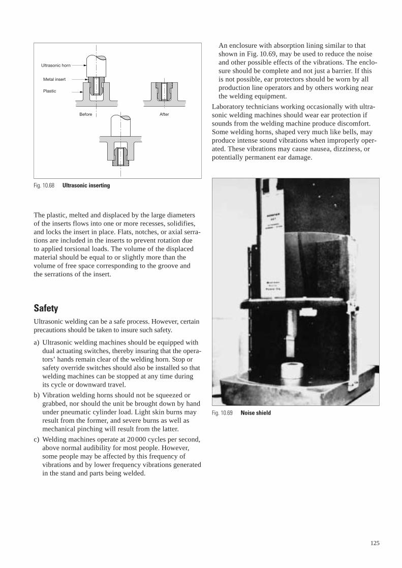
The plastic, melted and displaced by the large diametersof the inserts flows into one or more recesses, solidifies,and locks the insert in place. Flats, notches, or axial serra-tions are included in the inserts to prevent rotation due to applied torsional loads. The volume of the displacedmaterial should be equal to or slightly more than the volume of free space corresponding to the groove and the serrations of the insert.
SafetyUltrasonic welding can be a safe process. However, certainprecautions should be taken to insure such safety.
a) Ultrasonic welding machines should be equipped withdual actuating switches, thereby insuring that the opera-tors’ hands remain clear of the welding horn. Stop orsafety override switches should also be installed so thatwelding machines can be stopped at any time duringits cycle or downward travel.
b) Vibration welding horns should not be squeezed orgrabbed, nor should the unit be brought down by handunder pneumatic cylinder load. Light skin burns mayresult from the former, and severe burns as well asmechanical pinching will result from the latter.
c) Welding machines operate at 20 000 cycles per second,above normal audibility for most people. However,some people may be affected by this frequency ofvibrations and by lower frequency vibrations generatedin the stand and parts being welded.
Fig. 10.68 Ultrasonic inserting
Ultrasonic horn
Metal insert
Plastic
AfterBefore
An enclosure with absorption lining similar to thatshown in Fig. 10.69, may be used to reduce the noiseand other possible effects of the vibrations. The enclo-sure should be complete and not just a barrier. If this is not possible, ear protectors should be worn by allproduction line operators and by others working nearthe welding equipment.
Laboratory technicians working occasionally with ultra-sonic welding machines should wear ear protection ifsounds from the welding machine produce discomfort.Some welding horns, shaped very much like bells, mayproduce intense sound vibrations when improperly oper-ated. These vibrations may cause nausea, dizziness, orpotentially permanent ear damage.
Fig. 10.69 Noise shield
125
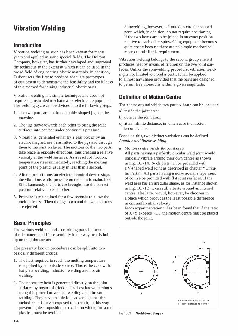
Vibration Welding
IntroductionVibration welding as such has been known for manyyears and applied in some special fields. The DuPontCompany, however, has further developed and improvedthe technique to the extent at which it can be used in thebroad field of engineering plastic materials. In addition,DuPont was the first to produce adequate prototypesof equipment to demonstrate the feasibility and usefulnessof this method for joining industrial plastic parts.
Vibration welding is a simple technique and does notrequire sophisticated mechanical or electrical equipment.The welding cycle can be divided into the following steps:
1. The two parts are put into suitably shaped jigs on themachine.
2. The jigs move towards each other to bring the jointsurfaces into contact under continuous pressure.
3. Vibrations, generated either by a gear box or by anelectric magnet, are transmitted to the jigs and throughthem to the joint surfaces. The motions of the two partstake place in opposite directions, thus creating a relativevelocity at the weld surfaces. As a result of friction,temperature rises immediately, reaching the meltingpoint of the plastic, usually in less than a second.
4. After a pre-set time, an electrical control device stopsthe vibrations whilst pressure on the joint is maintained.Simultaneously the parts are brought into the correctposition relative to each other.
5. Pressure is maintained for a few seconds to allow themelt to freeze. Then the jigs open and the welded partsare ejected.
Basic PrinciplesThe various weld methods for joining parts in thermo-plastic materials differ essentially in the way heat is builtup on the joint surface.
The presently known procedures can be split into twobasically different groups:
1. The heat required to reach the melting temperature is supplied by an outside source. This is the case with:hot plate welding, induction welding and hot air welding.
2. The necessary heat is generated directly on the jointsurfaces by means of friction. The best known methodsusing this procedure are spinwelding and ultrasonicwelding. They have the obvious advantage that themelted resin is never exposed to open air, in this waypreventing decomposition or oxidation which, for someplastics, must be avoided.
126
Spinwelding, however, is limited to circular shapedparts which, in addition, do not require positioning. If the two items are to be joined in an exact positionrelative to each other spinwelding equipment becomesquite costly because there are no simple mechanicalmeans to fulfill this requirement.
Vibration welding belongs to the second group since itproduces heat by means of friction on the two joint sur-faces. Unlike the spinwelding procedure, vibration weld-ing is not limited to circular parts. It can be applied to almost any shape provided that the parts are designedto permit free vibrations within a given amplitude.
Definition of Motion CentreThe centre around which two parts vibrate can be located:
a) inside the joint area;
b) outside the joint area;
c) at an infinite distance, in which case the motionbecomes linear.
Based on this, two distinct variations can be defined:Angular and linear welding.
a) Motion centre inside the joint areaAll parts having a perfectly circular weld joint wouldlogically vibrate around their own centre as shown in Fig. 10.71A. Such parts can be provided with a V-shaped weld joint as described in chapter ‘‘Circu-lar Parts’’. All parts having a non-circular shape mustof course be provided with flat joint surfaces. If theweld area has an irregular shape, as for instance shownin Fig. 10.71B, it can still vibrate around an internalcentre. The latter would, however, be choosen in a place which produces the least possible difference in circumferential velocity.From experimentation it has been found that if the ratioof X/Y exceeds ~1,5, the motion centre must be placedoutside the joint.
X
Y
A B
X = max. distance to centerY = min. distance to center
Fig. 10.71 Weld Joint Shapes
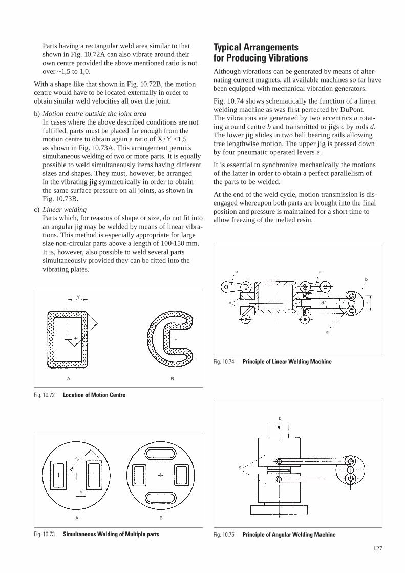
Parts having a rectangular weld area similar to thatshown in Fig. 10.72A can also vibrate around theirown centre provided the above mentioned ratio is notover ~1,5 to 1,0.
With a shape like that shown in Fig. 10.72B, the motioncentre would have to be located externally in order toobtain similar weld velocities all over the joint.
b) Motion centre outside the joint areaIn cases where the above described conditions are notfulfilled, parts must be placed far enough from themotion centre to obtain again a ratio of X / Y <1,5 as shown in Fig. 10.73A. This arrangement permitssimultaneous welding of two or more parts. It is equallypossible to weld simultaneously items having differentsizes and shapes. They must, however, be arranged in the vibrating jig symmetrically in order to obtain the same surface pressure on all joints, as shown inFig. 10.73B.
c) Linear weldingParts which, for reasons of shape or size, do not fit intoan angular jig may be welded by means of linear vibra-tions. This method is especially appropriate for largesize non-circular parts above a length of 100-150 mm. It is, however, also possible to weld several partssimultaneously provided they can be fitted into thevibrating plates.
Y
X
X
Y
+
A B
A B
Fig. 10.72 Location of Motion Centre
Fig. 10.73 Simultaneous Welding of Multiple parts
Typical Arrangements for Producing VibrationsAlthough vibrations can be generated by means of alter-nating current magnets, all available machines so far havebeen equipped with mechanical vibration generators.
Fig. 10.74 shows schematically the function of a linearwelding machine as was first perfected by DuPont. The vibrations are generated by two eccentrics a rotat-ing around centre b and transmitted to jigs c by rods d.The lower jig slides in two ball bearing rails allowingfree lengthwise motion. The upper jig is pressed downby four pneumatic operated levers e.
It is essential to synchronize mechanically the motionsof the latter in order to obtain a perfect parallelism ofthe parts to be welded.
At the end of the weld cycle, motion transmission is dis-engaged whereupon both parts are brought into the finalposition and pressure is maintained for a short time toallow freezing of the melted resin.
Fig. 10.74 Principle of Linear Welding Machine
Fig. 10.75 Principle of Angular Welding Machine
e
c
e
b
d
a
f
a
b
127
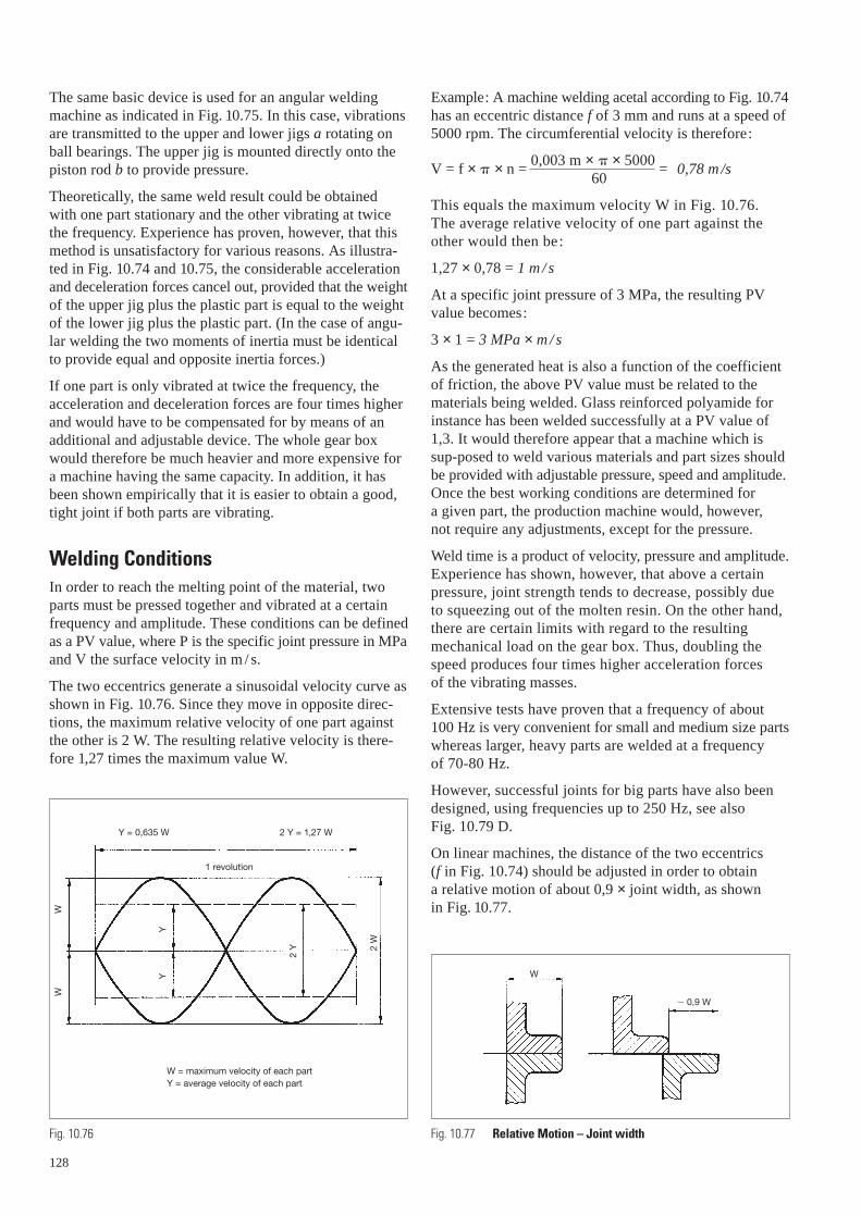
The same basic device is used for an angular weldingmachine as indicated in Fig. 10.75. In this case, vibrationsare transmitted to the upper and lower jigs a rotating onball bearings. The upper jig is mounted directly onto thepiston rod b to provide pressure.
Theoretically, the same weld result could be obtainedwith one part stationary and the other vibrating at twicethe frequency. Experience has proven, however, that thismethod is unsatisfactory for various reasons. As illustra-ted in Fig. 10.74 and 10.75, the considerable accelerationand deceleration forces cancel out, provided that the weightof the upper jig plus the plastic part is equal to the weightof the lower jig plus the plastic part. (In the case of angu-lar welding the two moments of inertia must be identicalto provide equal and opposite inertia forces.)
If one part is only vibrated at twice the frequency, theacceleration and deceleration forces are four times higherand would have to be compensated for by means of anadditional and adjustable device. The whole gear boxwould therefore be much heavier and more expensive fora machine having the same capacity. In addition, it hasbeen shown empirically that it is easier to obtain a good,tight joint if both parts are vibrating.
Welding ConditionsIn order to reach the melting point of the material, twoparts must be pressed together and vibrated at a certainfrequency and amplitude. These conditions can be definedas a PV value, where P is the specific joint pressure in MPaand V the surface velocity in m / s.
The two eccentrics generate a sinusoidal velocity curve asshown in Fig. 10.76. Since they move in opposite direc-tions, the maximum relative velocity of one part againstthe other is 2 W. The resulting relative velocity is there-fore 1,27 times the maximum value W.
Y = 0,635 W 2 Y = 1,27 W
1 revolution
W = maximum velocity of each partY = average velocity of each part
W
W
Y
Y
2 Y 2
W
Fig. 10.76
128
Example: A machine welding acetal according to Fig. 10.74has an eccentric distance f of 3 mm and runs at a speed of5000 rpm. The circumferential velocity is therefore:
V = f × × n = 0,003 m × × 5000
= 0,78 m /s60
This equals the maximum velocity W in Fig. 10.76. The average relative velocity of one part against theother would then be:
1,27 × 0,78 = 1 m / s
At a specific joint pressure of 3 MPa, the resulting PVvalue becomes:
3 × 1 = 3 MPa × m / s
As the generated heat is also a function of the coefficientof friction, the above PV value must be related to thematerials being welded. Glass reinforced polyamide forinstance has been welded successfully at a PV value of1,3. It would therefore appear that a machine which issup-posed to weld various materials and part sizes shouldbe provided with adjustable pressure, speed and amplitude.Once the best working conditions are determined for a given part, the production machine would, however, not require any adjustments, except for the pressure.
Weld time is a product of velocity, pressure and amplitude.Experience has shown, however, that above a certainpressure, joint strength tends to decrease, possibly due to squeezing out of the molten resin. On the other hand,there are certain limits with regard to the resultingmechanical load on the gear box. Thus, doubling thespeed produces four times higher acceleration forces of the vibrating masses.
Extensive tests have proven that a frequency of about 100 Hz is very convenient for small and medium size partswhereas larger, heavy parts are welded at a frequency of 70-80 Hz.
However, successful joints for big parts have also beendesigned, using frequencies up to 250 Hz, see also Fig. 10.79 D.
On linear machines, the distance of the two eccentrics (f in Fig. 10.74) should be adjusted in order to obtain a relative motion of about 0,9 × joint width, as shown in Fig. 10.77.
W
� 0,9 W
Fig. 10.77 Relative Motion – Joint width

c
a
ba
d
a b c d e
Fig. 10.78 Joint Design – Circular Parts
The specific surface pressure giving the highest jointstrength must be determined by testing. As a basic rule it can be said that a machine should be capable of produc-ing appr. 4 MPa of pressure on the surface to be welded.
Joint Design
a) Circular partsCircular parts should always be provided with a V-shapedjoint as used for spinwelding. Not only does such a designpermit perfect alignment of the two halves but the weldedsurface can be increased, thus reaching the strength of thewall section. During welding operations a certain amountof flash builds up on both sides of the joint. For certainapplications this must be avoided either for aesthetic rea-sons or because it may be a source of trouble for internalmechanical parts. In such cases, joints should be providedwith flash traps.
In order to transmit vibrations to the joint area, with theleast possible loss, the plastic part must be held firmly inthe jig. It is often advisable to provide the joint with 6 or8 driving ribs, especially for thin wall vessels in softmaterials.
A typical joint design with an external flash trap and driving ribs directly located on the shoulder is shown in Fig. 10.78a. There are a few basic requirements to bekept in mind:
– Before welding, the flat areas should be separated bygap c, which is appr. 0,1 the wall thickness.
– The angle b should not be less than 30° in order to avoida self locking effect.
– The welded length c + d must be at least 2,5× the wallthickness, depending on the desired strength. As someplastics are more difficult to weld than others, this valueshould be increased accordingly.
Fig. 10.78b and 10.78c show other possible arrangementsfor external flash traps.
On parts for which an aesthetic appearance is not essen-tial a simple groove like that in Fig. 10.78d is often suffi-cient. It does not cover the flash but keeps it within theexternal diameter.
If both internal and external flash traps are required theycan be designed for as shown in Fig. 10.78e.
b) Non circular partsNon circular parts, whether they are welded on angular orlinear machines can be provided with flat joints as shownin Fig. 10.79A. The joint width W should be at least twicethe wall thickness, depending again on strength require-ments and the plastic used. Strength does not increase significantly above a ratio W/ T = 2,5–3,0, due to unequalstress distribution (see also Fig. 10.81).
Square and rectangular shaped parts, especially with thinwalls or moulded in soft plastics are not stiff enough totransmit vibrations without loss. They must thereforehave a joint as shown in Fig. 10.79B with a groove aroundthe whole circumference. This groove fits onto a bead onthe jig a to prevent the walls from collapsing inwards. Itis most important to support the joint on both surfaces band c to achieve perfect weld pressure distribution.
A possible way of adapting flash traps on butt joints isshown in Fig. 10.79C. Gap a must be adjusted to obtain a complete closure of the two outer lips after welding.This design reduces the effective weld surface and mayneed wider joints for a given strength.
Another joint design, with flash trap, is shown in Fig. 10.79D. This joint has been used successfully invibration welding of covers for air-intake manifolds atfrequencies of up to 250 Hz, with amplitudes of 1,2 mm.
129

Fig. 10.79 Joint Design – Non Circular Parts
R R
D
R = 0,1 T
3-3,5 T
bc
a
D
A B
D
2,0
2,0
2,0
1,0
2,0
3,0
5,0
7,0
2,5
1,5
==
2,5
C
B = 2-3 T
a
1,2
T 3 T
2,0
2,0
2,5-
3,0
DETAIL
Jig
Amplitude: 0,9 – 1,2 mm
Frequency: 240 – 280 Hz
Cover
Air intake
Dep
th o
f wel
d t
o b
e d
eter
min
ed
130
Test Results on Angular Welded Butt JointsThe rectangular box shown in Fig. 10.80 was used forextensive pressure tests in various DuPont materials.The burst pressure of any vessel is influenced by threemain factors:
– overall design
– material weldability
– joint design.
The results obtained and described below should there-fore be applied carefully to parts having different shapesand functions. The same part moulded in different plas-tics will show quite different behaviour. Whereas in somecases the weld may be the weakest spot, in other engin-eering plastic resins it may prove to be stronger than thepart itself.
Joint Strength versus Welded SurfaceFig. 10.81 shows the tensile strength as a function ofjoint width, obtained on the vessel shown in Fig. 10.80.A linear strength increase can be observed up to a ratioW/ T of appr. 2,5. Above this value the curve tends to flatten out and increasing the width does not furtherimprove strength.
1 1,5 2 2,5 3
BD
Burst pressure
Ratio WT
7 cm2
36
45
Fig. 10.80 Burst Pressure Test Piece
Fig. 10.81 Joint Strength versus Joint Size
W
T

Joint Strength versus Specific Weld PressureAs already mentioned, the appropriate specific weldpressure should be determined for each plastic materialby trials. For DELRIN® 500 for instance, it was found tobe about 3,3 MPa as plotted on the curve in Fig. 10.82.It appears that too high a pressure reduces joint strengthas well as too low a pressure.
All grades of DELRIN® are suitable for vibration welding.DELRIN® 500F gives the best results, whereas DELRIN® 100is somewhat inferior. Weld joints on parts in DELRIN® 100are usually the weakest area due to the high elongation ofthis resin. This was also the case for the test vessel shownin Fig. 10.80. The same part moulded in DELRIN® glassfilled resin does not break at the joint but in a corner,because of the lower elongation. It must also be kept inmind that coloured compositions have a lower weldstrength than the same grade in natural colour. This appliesto all polymers. Pigment loadings have a slight adverseeffect on properties. Even though the average strength values differ somewhat from one grade to another, it is surprising to notice that the upper limit of about 14 MPatensile strength is the same for most grades.
Vibration welding is equally suitable for all grades ofZYTEL® nylon resins. It allows many new and attractiveapplications for which no other weld procedure would beapplicable. The automotive industry in particular requiresvarious non-circular vessels and containers in the coolingcircuit as well as for emission control filters.
No special care has to be taken concerning water absorp-tion before welding, provided that the parts are stored at a relative humidity no higher than 50%.
Butt joints of parts in unreinforced polyamide are usuallystronger than the part itself. Fillers and glass fibres reducejoint strength depending on their quality. Thus 30% glassfibres cause a reduction of up to 50% in strength. Parts inthis resin must be designed very carefully.
2 3 4
Burst pressure
Specific weld pressure
Fig. 10.82 Specific Weld Pressure Influences Joint Strength
Design ExamplesFig. 10.83. A typical centrifugal pump design with anangular welded spiral housing in DELRIN®.
Fig. 10.84. An automotive tank in ZYTEL® nylon 66 resin.The joint is provided with a flash trap to avoid any postdeflashing operation.
Fig. 10.83 Centrifugal pump
Fig. 10.84 Automotive tank
131

Fig. 10.85. A linear welded motor bicycle petrol tank inZYTEL®. The groove in the joint collects flash, then a PVCprofile is snapped over the flange. This is one solutionwhich effectively hides the whole weld joint.
Fig. 10.86a. An angular welded, square shaped gasolinefilter housing in ZYTEL®. The joint is provided with agroove to retain the thin walls in the jigs, thus preventingthem from collapsing during the welding operation.
Fig. 10.86b. An angular welded container in ZYTEL®.Body and cover house connections must be oriented inthe given position. A classic spinweld joint with an exter-nal flash trap is used for this vibration welding technique.
Fig. 10.87. Rubber diaphragm assemblies can also bewelded by angular vibrations. Steps must be taken, how-ever, to prevent the upper part from transmitting vibra-tions directly to the rubber. This can be achieved bymeans of a very thin nylon washer onto the diaphragm,the use of graphite powder or a drop of oil. The solenoid
132
Fig. 10.85 Motor bicycle petrol tank
Fig. 10.86 Angular Welded Parts
a b
valve in ZYTEL® glass fibre reinforced nylon resin shownhere has a burst pressure of 8-9 MPa. A significant advan-tage over self tapping screw assemblies lies in the factthat a welded body remains tight up to the burst pressure.
Comparison with other Welding TechniquesVibration welding is by no means a rival to ultrasonicwelding although in some cases they may compete. The solenoid valve shown in Fig. 10.87 can for instanceeasily be welded ultrasonically. However, the high frequency can cause the thin metal spring to break, inwhich case the whole housing must be scrapped. Sometimes a complicated part shape does not allow thewelding horn to come close enough to the joint. In addi-tion gas and air tight ultrasonic joints require close toler-ances which cannot always be achieved.
Thin wall vessels such as pocket lighters can never beprovided with a large enough joint to reach the requiredburst pressure. It would therefore be unwise to weld themon a vibration machine. Here ultrasonic welding is thepreferred technique.
Vibration welding can be considered in many applicationsas a rival to hot plate welding against which it offerssome considerable advantages:
– much shorter overall cycle;
– lower sensitivity to warpage, as the relatively high weldpressure flattens the parts out;
– since the molten resin is not exposed to air, the proce-dure is also suitable for all polyamide grades.
Vibration welding is not a competitor to pure spinwelding.For all circular parts which do not require a determinedposition to each other, spinwelding is still the cheapestand fastest assembly technique.
Fig. 10.87 Housing for diaphragm

Design Considerations for Vibration Welded PartsParts which are intended to be assembled by vibrationwelding must be designed correctly to avoid rejects and failures. Perfect fitting of the joint area is essential.
The first step is to choose an adequate joint giving therequired strength and tightness. It should be decided atthis stage of development whether flash traps or means to cover or conceal the joint are necessary.
It is essential to support the joint flange all around thepart in order to maintain equal pressure over the wholeweld area.
If, as shown in Fig. 10.88, the jig cannot fulfill this require-ment due to an interruption, weak spots or leakage can beexpected.
Thin ribs, however, are permissible, provided their thickness does not exceed appr. 80% of the wall section(Fig. 10.89).
Special care must be taken to make sure vibrations aretransmitted from the jig to the part with as little powerloss as possible. Such loss may occur from too muchclearance in the jig or because the part is held too faraway from the joint.
Circular parts without protruding features allowing a tightgrip must be provided with ribs as shown in Fig. 10.78a.
With parts having relatively thin walls or which aremoulded in soft materials, vibrations should be trans-mitted to the part as near to the joint area as possible. For non-circular parts this is often only possible with a design similar to that shown in Fig. 10.79b, regardlessof whether it is a linear or angular weld.
L = 0,8 T T
Fig. 10.88 Bad joint design
Fig. 10.89 Ribs in Vibration Welded Parts
Some materials which have a high coefficient of friction,as for instance elastomers, require an initial surface lubri-fication before they can be satisfactorily vibrated andwelded.
The amount of melt produced during the vibration cycleis in direct relation to the surface flatness. Stiff parts,especially in glass filled resins, may not be flattened outcompletely by the weld pressure and so require longervibration cycles to achieve good joints. When designingand moulding such parts, it should therefore be kept in mind that the total assembly time depends partially on joint levelness which in turn can often be improvedwith appropriate design.
Fig. 10.90a Vibration welding machine.
133
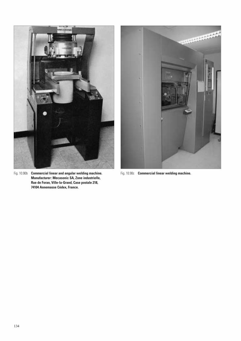
Fig. 10.90b Commercial linear and angular welding machine.Manufacturer: Mecasonic SA, Zone industrielle, Rue de Foran, Ville-la-Grand, Case postale 218, 74104 Annemasse Cédex, France.
134
Fig. 10.90c Commercial linear welding machine.
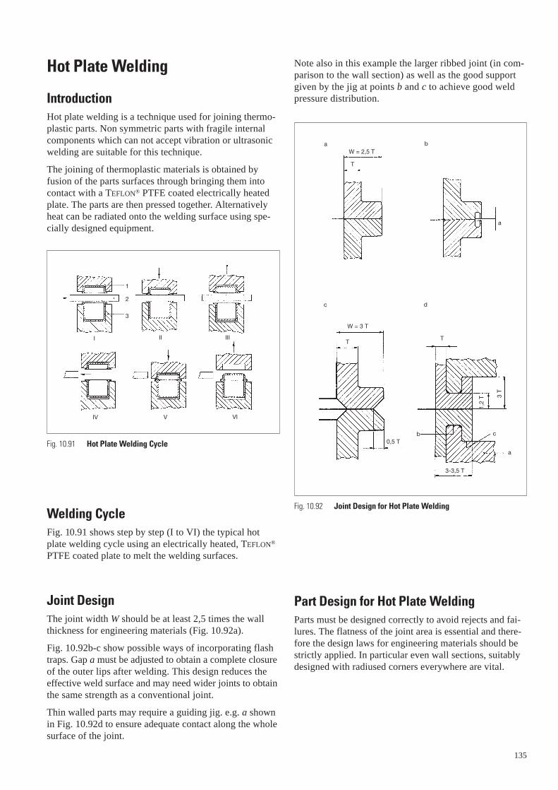
Hot Plate Welding
IntroductionHot plate welding is a technique used for joining thermo-plastic parts. Non symmetric parts with fragile internalcomponents which can not accept vibration or ultrasonicwelding are suitable for this technique.
The joining of thermoplastic materials is obtained byfusion of the parts surfaces through bringing them intocontact with a TEFLON® PTFE coated electrically heatedplate. The parts are then pressed together. Alternativelyheat can be radiated onto the welding surface using spe-cially designed equipment.
Welding CycleFig. 10.91 shows step by step (I to VI) the typical hotplate welding cycle using an electrically heated, TEFLON®
PTFE coated plate to melt the welding surfaces.
Joint DesignThe joint width W should be at least 2,5 times the wallthickness for engineering materials (Fig. 10.92a).
Fig. 10.92b-c show possible ways of incorporating flashtraps. Gap a must be adjusted to obtain a complete closureof the outer lips after welding. This design reduces theeffective weld surface and may need wider joints to obtainthe same strength as a conventional joint.
Thin walled parts may require a guiding jig. e.g. a shownin Fig. 10.92d to ensure adequate contact along the wholesurface of the joint.
I II III
IV V VI
1
2
3
Fig. 10.91 Hot Plate Welding Cycle
Note also in this example the larger ribbed joint (in com-parison to the wall section) as well as the good supportgiven by the jig at points b and c to achieve good weldpressure distribution.
Part Design for Hot Plate WeldingParts must be designed correctly to avoid rejects and fai-lures. The flatness of the joint area is essential and there-fore the design laws for engineering materials should bestrictly applied. In particular even wall sections, suitablydesigned with radiused corners everywhere are vital.
Fig. 10.92 Joint Design for Hot Plate Welding
a
T
W = 2,5 T
W = 3 T
T
0,5 T
T
b
3-3,5 T
a
c
1,2
T 3 T
a b
c d
135

Limitations of Hot Plate Welding– Polyamide based resins are in general unsuitable for hot
plate welding since they oxidise when the melted resin is exposed to air during the welding cycle. The oxidisedmaterial will not weld properly.
– Relative to other plastics welding techniques, cycles arelong (in the range 30–45 s).
– Some sticking problems between the polymer and thehot plate are possible. TEFLON® PTFE coating of theplate tends to reduce this considerably.
– Only similar materials can be joined by this method.
Practical ExamplesPractical applications of Hot plate welding are shown inFig. 10.93.
Fig. 10.93 Applications of Hot Plate Weldinga – Gas meter parts
b – Drain part
136
Hot Plate Welding of ZYTEL®
One of the main problems in welding ZYTEL® nylon 66 isoxidisation and speed of crystallization. Unlike the shearjoint as used in Ultrasonic welding or the joint used inVibration welding, the surface of the joint is exposed tocold air when the hot plate is removed to allow the twoparts ot come together. During this time the plastic willtend to oxidise and result in a poor weld.
But with care and attention to certain parameters, ZYTEL®
can be hot plate welded to give a weld of good strength in relation to the parent material strength.
The ZYTEL® must be dry as moulded. Welding immediatelyafter moulding is the ideal case, although a delay of 48 hoursis acceptable. If this is not practical the parts must be dried to a moisture content below 0,2%. The effect of moisture onthe weld quality is quite dramatic. A frothy weld flash willbe observed indicating a “wet” material, moisture will pro-mote oxidisation and porosity in the weld and thus reducesthe strength of the weld by up to 50%.
Fillers in the plastic will also effect the weld strength. The strongest joint will be achieved with the natural unre-inforced Nylon. Glass fibres will obviously not weld toeach other and will not move across the weld joint, thisgives a similar weakness as a weld line in a moulded part,up to 50% reduction in strength. The strength of the joint is inversely proportional to the glass content. More glass = lower strength. Carbon black will alsoadversely affect the weld quality.
Hot plate temperature. Normally as a general rule thetemperature of the plate is set to +20° C above the melttemperature of the plastic to be welded.
In the case of ZYTEL® nylon 66 with a melt temperatureof 262° C, the plate temperature would be around285° C. Attention must now be paid to the TEFLON® orPTFE coating on the plates to avoid sticking, because at this temperature the TEFLON® coating will start tofume off.
c – Lighter

At a temperature of 270–275° C, the TEFLON® will beginto fume off and the PTFE tape to visibly bubble. To avoidthis problem the temperature of the plate should be265–270° C. This is below the + 20° C rule so a longerheat soak time should be used to compensate for thelower temperature. Another problem with welding at ele-vated temperatures is that at around 275° C the aluminiumplate will warp. To over come this problem AluminiumBronze plates should be used, these can go up to 500° C.
The jigging of the tow components is quite important. If the jig is made from metal and comes quite high up thepart close to the weld line, it will act as a large heat sink,taking away the heat built up in the part durring the heatsoak phase. Fast cooling of the parts result in a fast rate ofcrystallization not allowing the plastic to weld efficiently.Slow cooling is prefered. Non metallic jigs are a solution.
Fig. 10.94 Hot plate welding machine.
Other parametersHeat soak time, is part and joint dependant, normally in the area of 15 s / min.
Cooling / hold time, similar to heat soak time.
Pressures during weld phase from 0,5 to 2 MPa = 5 to 20 bar.
Joint design, the general rule for the joint dimension is2,5 × thickness. Tests have shown that if the general wallthickness is 2 mm the weld joint should be 5 mm thick, in order to give a joint strength comparable with the wallstrength. Depending on the conditions in service of thepart, maximum strength may not be required. For examplea small breather pipe would not need such a high weldstrength as a mounting bracket. So a thinner weld jointcan be used, 1,5 to 2 × t. With less surface area to heatsoak the cycle times will be quicker.
137
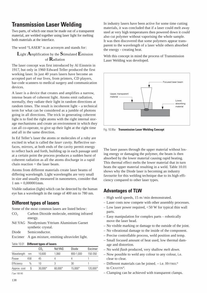
Transmission Laser WeldingTwo parts, of which one must be made out of a transparentmaterial, are welded together using laser light for meltingboth materials at the interface.
The word “LASER” is an acronym and stands for:
Light Amplification by the Stimulated Emission
of Radiation
The laser concept was first introduced by Al Einstein in1917, but only in 1960 Edward Teller produced the firstworking laser. In just 40 years lasers have become anaccepted part of our lives, from printers, CD players, bar-code scanners to medical surgery and communicationdevices.
A laser is a device that creates and amplifies a narrow,intense beam of coherent light. Atoms emit radiation, normally, they radiate their light in random directions atrandom times. The result is incoherent light – a technicalterm for what can be considered as a jumble of photonsgoing in all directions. The trick in generating coherentlight is to find the right atoms with the right internal stor-age mechanisms and create an environment in which theycan all co-operate, to give up their light at the right timeand all in the same direction.
In Ed Teller’s laser the atoms or molecules of a ruby areexcited in what is called the laser cavity. Reflective sur-faces, mirrors, at both ends of the cavity permit energy to reflect back and forth, building up in each passage untilat a certain point the process produces a sudden burst ofcoherent radiation as all the atoms discharge in a rapidchain reaction = the laser beam.
Atoms from different materials create laser beams of differing wavelength. Light wavelengths are very small in size and usually measured in nanometers, consider that1 nm = 0,000001mm.
Visible radiation (light) which can be detected by the humaneye has a wavelength in the range of 400 nm to 780 nm.
Different types of lasersSome of the most common lasers are listed below:CO2 Carbon Dioxide molecule, emitting infrared
energy.Nd:YAG Neodymium:Yttrium Aluminium Garnet
synthetic crystal.Diode Semiconductor.Excimer A gas mixture, emitting ultraviolet light.
Table 10.01 Different types of lasers
CO2 Nd:YAG Diode Excimer
Wavelength nm 10,600 1,060 800-1,000 150-350
Power KW 45 4 4 1
Efficiency % 10 3 30 1
Approx. cost $ 30,000* 60,000* 15,000* 120,000*
(*per 100 W)
138
In industry lasers have been active for some time cuttingmaterials, it was concluded that if a laser could melt awaysteel at very high temperatures then powered down it couldalso cut polymer without vaporising the whole sample. It was then discovered that some polymers appear trans-parent to the wavelength of a laser while others absorbedthe energy - creating heat.
With this concept in mind the process of TransmissionLaser Welding was developed.
The laser passes through the upper material without los-ing energy or damaging the polymer, the beam is thenabsorbed by the lower material causing rapid heating.This thermal effect melts the lower material that in turnheats the upper material resulting in a weld. Table 10.01shows why the Diode laser is becoming an industryfavourite for this welding technique due to its high effi-ciency compared to other laser types.
Advantages of TLW– High weld speeds, 15 m / min demonstrated.– Laser costs now compete with other assembly processes.– Low laser power required, <50 W for typical thin wall
parts.– Easy manipulation for complex parts – robotically
move the laser head.– No visible marking or damage to the outside of the joint.– No vibrational damage to the inside of the component.– Precise controllable process, weld position and temp.– Small focused amount of heat used, low thermal dam-
age and distortion.– No weld flash produced, very shallow melt down.– Now possible to weld any colour to any colour, i.e.
clear to clear. – Different materials can be joined. – i.e. HYTREL®
to CRASTIN®.– Clamping can be achieved with transparent clamps.
Fig. 10.95a Transmission Laser Welding Concept
Upper, transparentmaterial
Lower, absorbing material
Focused laser beam
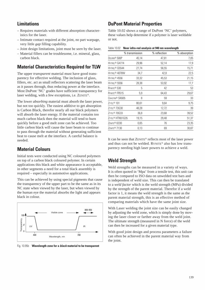
Limitations– Requires materials with different absorption character-
istics for the laser.– Intimate contact required at the joint, no part warpage,
very little gap filling capability.– Joint design limitations, joint must be seen by the laser.– Material fillers can be troublesome, i.e. mineral, glass,
carbon black.
Material Characteristics Required for TLWThe upper transparent material must have good trans-parency for effective welding. The inclusion of glass,fillers, etc. act as small reflectors scattering the laser beamas it passes through, thus reducing power at the interface.Most DuPont ‘NC’ grades have sufficient transparency forlaser welding, with a few exceptions, i.e. ZENITE®.
The lower absorbing material must absorb the laser power,but not too quickly. The easiest additive to get absorptionis Carbon Black, therefor nearly all our black polymerswill absorb the laser energy. If the material contains toomuch carbon black then the material will tend to burnquickly before a good melt zone can be achieved. Too little carbon black will cause the laser beam to continue to pass through the material without generating sufficientheat to cause melt at the interface. A careful balance isneeded.
Material ColoursInitial tests were conducted using NC coloured polymerson top of a carbon black coloured polymer. In certainapplications this black and white appearance is acceptable,in other segments a need for a total black assembly isrequired – especially in automotive applications.
This can be achieved by using special pigments that causethe transparency of the upper part to be the same as in itsNC state when viewed by the laser, but when viewed bythe human eye the material absorbs the light and appearsblack in colour.
800-950
100
0
400 780
Fig. 10.95b Wavelength zone for a black material to be transparent
Wavelength, nm
Visible zone
UV IR
Tran
spar
ency
, %
DuPont Material PropertiesTable 10.02 shows a range of DuPont ‘NC’ polymers,these values help determine if a polymer is laser weldableor not.
Table 10.02 Near infra-red analysis at 940 nm wavelength
% transmission % reflection % absorption
DELRIN® 500P 45,14 47,81 7,05
HYTREL® G4774 29,96 52,14 17,9
HYTREL® G5544 27,74 56,55 15,71
HYTREL® 4078W 34,7 42,8 22,5
HYTREL® 4556 33,32 45,53 21,15
HYTREL® 5556 28,38 53,92 17,7
RYNITE® 530 5 42 53
RYNITE® FR515 5,9 64,43 29,67
CRASTIN® SK605 8 59 33
ZYTEL® 101 80,61 9,64 9,75
ZYTEL® 73G30 48,28 12,72 39
ZYTEL® 70G33 36,8 23,68 39,52
ZYTEL® HTN51G35 19,15 29,48 51,37
ZENITE® 6330 0,65 76 23,35
ZENITE® 7130 0,13 69 30,87
It can be seen that ZENITE® reflects most of the laser powerand thus can not be welded. RYNITE® also has low trans-parency needing high laser powers to achieve a weld.
Weld StrengthWeld strengths can be measured in a variety of ways. It is often quoted in ‘Mpa’ from a tensile test, this unit canthen be compared to ISO data on unwelded test bars andis independent of weld size. This can then be translated to a weld factor which is the weld strength (MPa) dividedby the strength of the parent material. Therefor if a weldfactor is 1, it means the weld strength is the same as theparent material strength, this is an effective method ofcomparing materials which have the same joint size.
With Laser welding the joint size can be easily changedby adjusting the weld zone, which is simply done by mov-ing the laser closer or farther away from the weld joint.The ultimate strength (measured in N force) of the weldcan then be increased for a given material type.
With good joint design and process parameters a failurecan often be achieved in the parent material way from the joint.
139

Typical Joint Designs
Fig. 10.95c Variations of laser weld joint designs
Machine Suppliers and InstitutesVarious well known assembly machine manufacturers areactive in “TLW”, Branson and Bielomatik of Germanyhave commercial laser welding machines, although theirobjective is not to replace vibration, hot plate and ultra-sonic welding machines, but to offer it as an alternativeprocess. Their machines have a range of laser power up to 50 W.
Institutes such as the TWI in the UK and the FraunhoferInstitute in Germany are also very experienced and haveaccess to higher power lasers. Other machine manufactur-ers include Herfurth of the UK and Leister of Switzerland.
140
A Leister Diode laser machine is installed in Meyrin andhas the following features:Laser type = Diode LaserWavelength λ = 940 nmMax. power = 35 W‘Spot’ size = ∅ 0,6 mm to ∅ 3 mmMax. speed = 150 mm/sPositional accuracy = 2 mm
Also available within the DuPont organisation is a 500 Wdiode laser located in Japan.
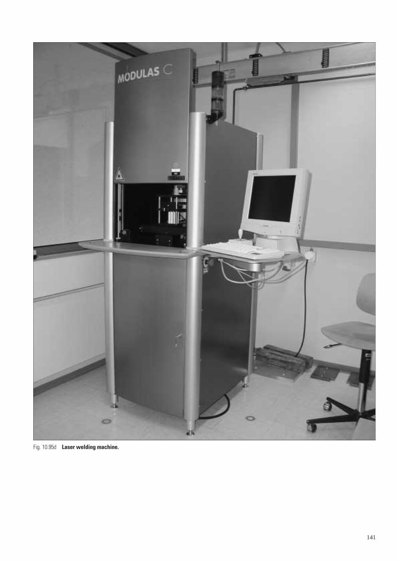
141
Fig. 10.95d Laser welding machine.
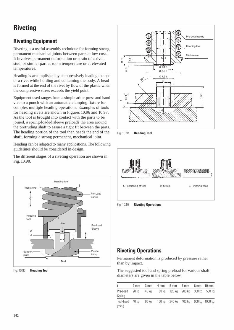
Riveting
Riveting EquipmentRiveting is a useful assembly technique for forming strong,permanent mechanical joints between parts at low cost. It involves permanent deformation or strain of a rivet,stud, or similar part at room temperature or at elevatedtemperatures.
Heading is accomplished by compressively loading the endor a rivet while holding and containing the body. A head is formed at the end of the rivet by flow of the plastic whenthe compressive stress exceeds the yield point.
Equipment used ranges from a simple arbor press and handvice to a punch with an automatic clamping fixture forcomplex multiple heading operations. Examples of toolsfor heading rivets are shown in Figures 10.96 and 10.97.As the tool is brought into contact with the parts to bejoined, a spring-loaded sleeve preloads the area aroundthe protruding shaft to assure a tight fit between the parts. The heading portion of the tool then heads the end of theshaft, forming a strong permanent, mechanical joint.
Heading can be adapted to many applications. The followingguidelines should be considered in design.
The different stages of a riveting operation are shown inFig. 10.98.
Heading tool
Tool stroke
Headingtool
Pilot
Pre-LoadSpring
Pre-LoadSleeve
Plasticfitting
D>d
Supportplate
Fig. 10.96 Heading Tool
D
d
142
Riveting OperationsPermanent deformation is produced by pressure ratherthan by impact.
The suggested tool and spring preload for various shaftdiameters are given in the table below.
t 2 mm 3 mm 4 mm 5 mm 6 mm 8 mm 10 mm
Pre-Load 20 kg 45 kg 80 kg 120 kg 200 kg 300 kg 500 kgSpring
Tool-Load 40 kg 90 kg 160 kg 240 kg 400 kg 600 kg 1000 kg(min.)
Pre-Load spring
Heading tool
Pilot sleeve1,0 t
Ø 1,4 t
Ø 2,5 t
Ø 1,5 t
Ø t
0,7
t
0,2
t
0,1
t
t 0,7
t
1,5
t
r 0,1 t
90 °
Fig. 10.97 Heading Tool
Fig. 10.98 Riveting Operations
1. Positioning of tool 2. Stroke 3. Finishing head
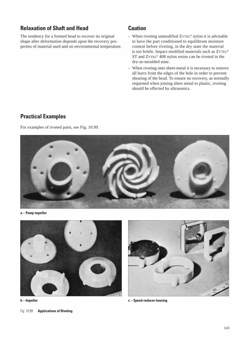
Relaxation of Shaft and HeadThe tendency for a formed head to recover its originalshape after deformation depends upon the recovery pro-perties of material used and on environmental temperature.
Practical Examples
For examples of riveted parts, see Fig. 10.99.
Fig. 10.99 Applications of Riveting
b – Impeller
a – Pump impeller
Caution– When riveting unmodified ZYTEL® nylon it is advisable
to have the part conditioned to equilibrum moisturecontent before riveting, in the dry state the material is too brittle. Impact modified materials such as ZYTEL®
ST and ZYTEL® 408 nylon resins can be riveted in thedry-as-moulded state.
– When riveting onto sheet-metal it is necessary to removeall burrs from the edges of the hole in order to preventshearing of the head. To ensure no recovery, as normallyrequested when joining sheet metal to plastic, rivetingshould be effected by ultrasonics.
143
c – Speed-reducer housing

Design for DisassemblyTo improve the recyclability of plastic parts, componentsshould be designed in such a way, that disassembly is possible wherever possible. Aspects which should beconsidered for this are:
• Use standard materials, whenever possible;
• When multiple materials have to be used in one part,use assembly techniques which allow easy disassemblyat a later stage; see also Table 10.03;
144
Table 10.03 Comparison of assembly techniques for plastic parts
Assembly technique Material combination
Screw arbitrary
Snap-fit arbitrary
Press-fit arbitrary
Welding family members
Bonding arbitrary
Overmoulding arbitrary
• Disassembly, when applicable, should be possible byusing robots;
The design should allow easy cleaning and re-use of thepart;
• The part material should be recognisable by part coding,for example >PA66-35 GF< for polyamide 66 with 35%glass fibre reinforcement;
• Inserts (other materials) should be easily removable, for example by using “breaking out” techniques.
Recyclability Disassembly
good good, but time consuming
very good good, when properly designed
good poor – reasonable
very good not possible (not always applicable)
poor poor
reasonable poor