10 chapter 7 evaluation of the intake facility
TRANSCRIPT

175
Chapter 7
Evaluation of the Intake Facility and 1957 Water Line Ward Tonsfeldt
The City of Bend Bridge Creek intake complex, located in the SE¼ NE¼ of Section 7, Township 18S, Range 10E, Willamette Meridian, on Tumalo Creek west of Bend (Figure 7.1), consists of a dam on Bridge Creek, a retaining wall/afterbay made of basaltic ashlars, intake pipes, obsolete nonoperational filtration equipment, and the intake building itself (Figure 7.2). All of this was finished and operating in 1926, but may have been modified subsequently. The proposed undertaking by the City of Bend would replace the above-grade portion of the intake building and incorporate new fish screens. The intake building foundation, dam structure, and retaining wall/afterbay would not be modified. If they are determined eligible for nomination to the National Register of Historic Places, and the proposed upgrades
Figure 7.1. Location of the City of Bend’s Bridge Creek Intake Facility near Tumalo Falls west of Bend (USGS Tumalo Falls Quad, 7.5’ Series, 1988).

Bend Water System Improvement Project
176
constitute an adverse effect, mitigation will be required. This chapter presents the context within which the facilities were constructed and operated, and an evaluation of their integrity. Also presented is a discussion of the 1954-1957 water line that will be impacted by construction.
Bend Municipal Water Supply The City of Bend began the 1920’s drawing of its municipal water from the Deschutes River at the hydro-electric dam in the center of town. A local utility, the Bend Water, Light, and Power Company (BWL&P), owned the system of delivery pipes that served residents. The utility company removed water from the Deschutes by pumping. Since Bend Water, Light, and Power produced the electricity to power their pumps, the system was economical and expedient. As long as the quality and quantity of water in the Deschutes were adequate, the system suited everyone. In 1915 large lumber producers Brooks Scanlon and Shevlin-Hixon had built mills on the Deschutes in Bend and began logging operations upstream from the town. The lumber companies built a dam across the Deschutes at the south end of town and impounded water for their jointly-used mill pond. Logs were dumped into the river and stored until they were fed into the mills’ giant bull chains. Storing the logs in the river kept them from drying out and loosened the accumulated dirt and grit from their journey out of the woods. Impounded water in the mill pond was cloudy and warm during the summer months. Algae bloomed in the pond and impaired the quality of the water entering the city’s water intake downstream (Bend Bulletin, Feb. 10, 1925: 6). In 1921, to supply increasing demands for irrigation water from the Deschutes, irrigation districts, in cooperation with state and federal agencies, built a large storage reservoir about 40 miles upstream of
Figure 7.2. Dam and intake building, looking west.

Chapter 7—Evaluation of the Intake Facility and 1957 Water Line
177
Fig
ure
7.3.
Map
acc
ompa
nyin
g re
port
fro
m D
ubui
s an
d K
oon
to th
e B
end
Cit
y C
ounc
il, D
ecem
ber
1924
.

Bend Water System Improvement Project
178
Bend at Crane Prairie. The reservoir was shallow and subject to summer algae blooms. By the early 1920s, it was apparent that the quality of Bend’s domestic water from the Deschutes was declining. The Bend Water, Light, and Power Co. filtered the water from the Deschutes and chlorinated it, but residents were not pleased with the odor and taste during the summer months (Bend Bulletin, Feb. 10, 1925: 6). By 1924, the Bend City Council was petitioning the State Board of Health to require the Corps of Engineers to open the dam at Crane Prairie to flush water down the river (Bend City Council minutes, June 9, 1924). The obvious long-term solution to the water situation was for Bend to find another supply. As early as 1919 Bend had looked for a new supply, and in 1923 the City directed engineers John Dubuis and R.E. Koon to report on sources of better water. In December of 1924, they presented their preliminary findings (Figure 7.3). Good quality surface water was available from Fall River, a spring-fed stream 25 miles south of Bend and from Tumalo Creek, a glacier-fed stream 12 miles west of Bend. Tumalo Creek presented the better opportunity since the pipeline would be half the length, and the 1500’ difference in elevation assured good gravity delivery to the city.
Tumalo Creek The problem with Tumalo Creek as a source of municipal water was that the rights were in constant turmoil, and development of irrigation for the Tumalo area had a 30-year history of fraud, incompetence, corruption, and abuse. In fact, the very word “Tumalo” had such negative connotations that the Tumalo residents changed the name of their water district, and the citizens of Bend changed the name of their part of Tumalo Creek to “Bridge Creek.” Irrigation projects on Tumalo Creek and the appropriation of water rights began in 1893 with the formation of the Three Sisters Ditch Company. This became a Carey Act project after 1894 when the Carey Act was passed in Congress (Winch 1984: 349ff). The developers hired Bend civil engineer L. D. Weist to do some preliminary design on the system, which was projected to irrigate 27,000 acres of arid land north and east of the creek. By 1905, the original developers had been accused of fraud and the State Land Board asked the federal government to reject their second appropriation of public lands (Hall 1994: 17). The Three Sisters group sold to the Columbia Southern Irrigation, who operated the project until 1911, when they deeded the project to the Oregon, Washington, and Idaho Finance Co. In 1906 it became clear that without a storage reservoir the water in Tumalo Creek could not irrigate more than about 3000 acres, although over 15,000 acres had been sold with water promised (Winch 1985a: 52). In February of 1913, the Oregon Legislature passed the Columbia Southern Act, which authorized the State to take over ownership of the Tumalo Project from the Oregon, Washington, and Idaho Finance Co. The Legislature then created the Irrigation and Drainage Securities Commission to support Tumalo irrigation bonds with the State’s credit (Winch 1985c: 378). Within two years, Salem had demonstrated its progressive attitude (and deep pockets) by building the Tumalo Diversion Dam on Tumalo Creek, the Tumalo Feed Canal to provide extra water, and Tumalo Reservoir to store water for delivery during the summer. Unfortunately, these solutions didn’t work. The reservoir leaked most of its stored water into a lava tube, and additional water diverted through the Tumalo Feed Canal was not adequate to meet the users’ needs (Hall 1994: 18). Attempts to plug the leaky reservoir continued through 1950, but at present it holds less than 5% of its capacity. Water for the Tumalo Project required all of the water in the creek plus whatever water the State could scrounge from other projects fed by the Deschutes. The State reached a partial solution to the Tumalo problem in the early 1920s by allowing the Tumalo District to store Deschutes River water in Crane Prairie and Crescent Lake reservoirs and by building another canal—the Bend Feed Canal—to divert more Deschutes water to the Tumalo canals (Winch 1985a: 383). The Tumalo Irrigation District took the unusual step in 1922 of re-naming itself the

Chapter 7—Evaluation of the Intake Facility and 1957 Water Line
179
Deschutes County Municipal Improvement District in hopes that potential buyers for its bonds would not connect it with the name “Tumalo.”
Bend’s Water Plan In the summer of 1924, then, the City of Bend formally asked State land and water agencies for permission to develop a new municipal water supply. At its June 20, 1924, meeting The City Council authorized a delegation to go to Salem seeking a share of the already over-committed Tumalo Creek water. On January 6, 1925, the Mayor and the City Attorney returned to Salem to ask again for legal access to Tumalo Creek water. Their petition to exchange Deschutes water rights for Tumalo water rights was approved by the Legislature in October of 1925 (Bend City Council minutes, Oct. 28, 1925). This action required the Legislature to override the veto of Governor Oswald West, who was opposed to the exchange and believed he was protecting the Tumalo homesteaders (Winch 1985a: 389). The City’s plan was relatively straightforward: Bend would sell about $600,000 in new bonds to purchase the Bend Water, Light, and Power Company, build a pipeline from Tumalo Creek to Bend, and build municipal reservoirs on what is now known as Water Tank Hill. Bend Water, Light, and Power Company owned rights to water from the Deschutes. These would be exchanged for rights to Tumalo Creek water. Deschutes River water formerly used for Bend municipal supply would flow through the Bend Diversion Canal to the Tumalo system, and there would be no reduction in the net amount of irrigation for the Tumalo farmers. During the summer of 1925, the Bend Bulletin editorialized against the bond election (Bend Bulletin, July 27; August 4, 1925). However, the bond measure passed on August 5. In November of 1925 consulting engineers John Dubuis and R.E. Koon presented plans for the new system to the City Council. At their next meeting, November 20, the City Council opened bidding on the pipeline construction. On March 11 of the following year, the City accepted A.D. Kerns’ bid for $150,199 for a steel pipeline to be completed by November 1, 1926. At the same meeting, the City asked Dubuis and Koons to prepare plans for an intake structure on the South Fork of Tumalo Creek, the name of which would soon be sanitized as “Bridge Creek.” In April of 1926, the City agreed to buy Bend Water, Light, and Power for $238,107.56 (Bend City Council minutes, April 9, 1926). Their distribution system and their Deschutes water rights were essential to the City’s plan. The water rights exchange, blessed by the Legislature but resisted by Governor West and the Tumalo farmers, was consummated in 1926 with an added cash settlement to the financially desperate Tumalo Irrigation District. However, the situation was far from clear, and litigation over water rights between the City, the Tumalo District, and other interested parties would continue for decades (Winch 1986: 21ff).
Design and Operations of the Intake System The new water system had three major parts: the intake and the pipeline from Bridge Creek; the storage tanks on Water Tank Hill; and the distribution pipes in Bend, provided by the purchase of Bend Water, Light and Power. Dubuis and Koon designed the intake and pipeline. Both of these have served the City since 1926. The original pipeline was 14” in diameter near the intake, then 12” for the steepest hydraulic gradient, then 16” for the last two miles to the reservoir. The pipe was 8-gauge galvanized steel pipe provided by contractor A.D. Kern. In 1954 the city contracted with consulting engineer John W. Cunningham of Portland to prepare plans for a second steel pipeline to supplement the original pipeline. These two lines have continued to operate in tandem.

Bend Water System Improvement Project
180
Dubuis and Koon’s design and engineering work reflects the state of the art in 1920. In 1917, Armory Prescott Folwell published the third edition of his influential Water Supply Engineering: The Design and Construction of Water Supply Systems. Folwell notes that gravity systems (like the Bridge Creek system) are usually provided with a dam and reservoir at the intake to assure an adequate supply of water throughout the year. If the supply is adequate, however, a reservoir is not needed.
When it is not necessary to store water in order to obtain a continuous supply, storage reservoirs may be omitted and the impounding reservoir may be limited to a slight damming up of the stream. (Folwell 1917: 196)
DuBuis and Koon designed the Bridge Creek dam more to divert the water into the intake structure than to provide storage.
Figure 7.4. Plan of dam and intake building from 1926 design.
Chapter 7—Evaluation of the Intake Facility and 1957 Water Line
181
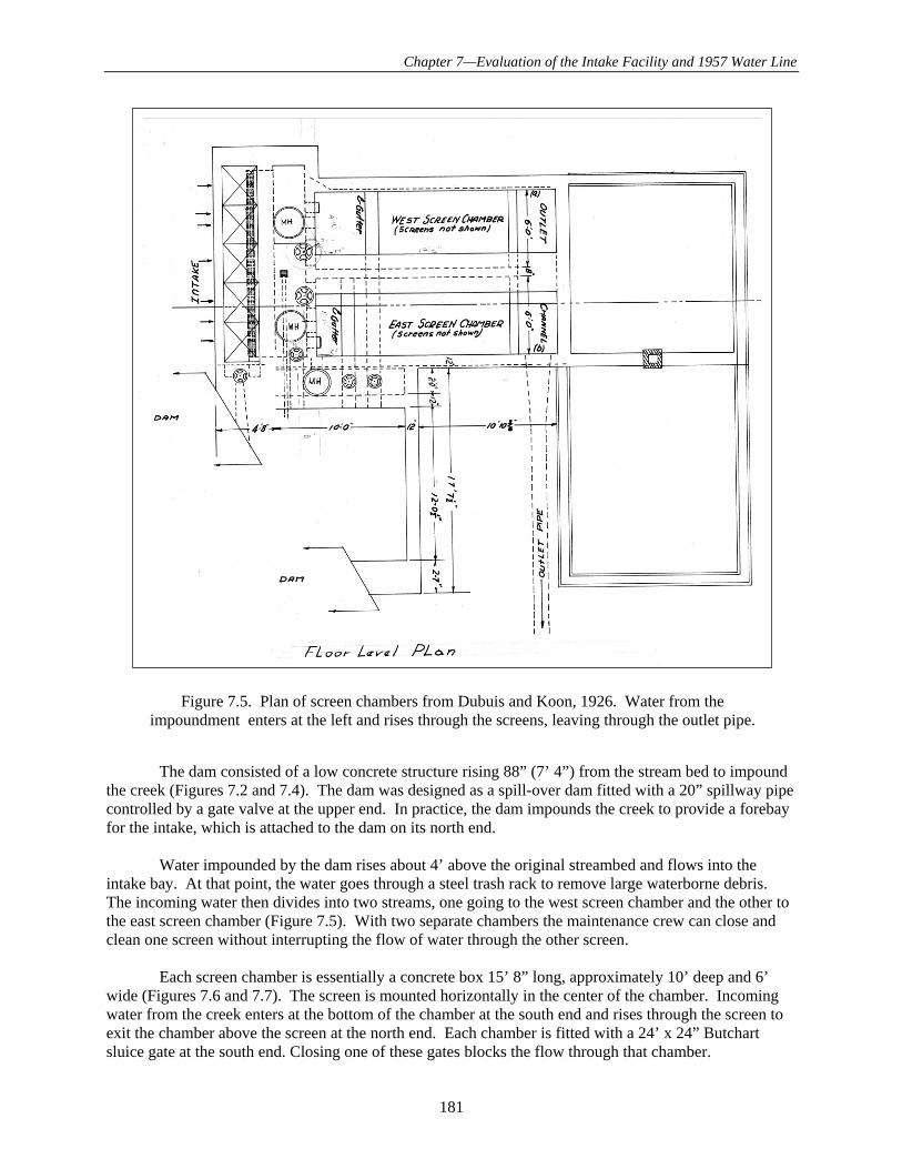
The dam consisted of a low concrete structure rising 88” (7’ 4”) from the stream bed to impound the creek (Figures 7.2 and 7.4). The dam was designed as a spill-over dam fitted with a 20” spillway pipe controlled by a gate valve at the upper end. In practice, the dam impounds the creek to provide a forebay for the intake, which is attached to the dam on its north end. Water impounded by the dam rises about 4’ above the original streambed and flows into the intake bay. At that point, the water goes through a steel trash rack to remove large waterborne debris. The incoming water then divides into two streams, one going to the west screen chamber and the other to the east screen chamber (Figure 7.5). With two separate chambers the maintenance crew can close and clean one screen without interrupting the flow of water through the other screen. Each screen chamber is essentially a concrete box 15’ 8” long, approximately 10’ deep and 6’ wide (Figures 7.6 and 7.7). The screen is mounted horizontally in the center of the chamber. Incoming water from the creek enters at the bottom of the chamber at the south end and rises through the screen to exit the chamber above the screen at the north end. Each chamber is fitted with a 24’ x 24” Butchart sluice gate at the south end. Closing one of these gates blocks the flow through that chamber.
Figure 7.5. Plan of screen chambers from Dubuis and Koon, 1926. Water from the impoundment enters at the left and rises through the screens, leaving through the outlet pipe.

Bend Water System Improvement Project
182
Figure 7.6. Sectional view of the screen chambers from Dubuis and Koon, 1926. Water enters at the lower left, rises through the screens, leaving the chambers through the outlet chamber in the center.
Figure 7.7. View of screen chambers, west chamber in foreground, looking north. The water enters at the bottom of the chambers at the south end, where the viewer is standing. It then wells up through the screens and leaves the chambers at the north end, where it enters the pipe to the reservoirs in Bend.

Chapter 7—Evaluation of the Intake Facility and 1957 Water Line
183
Fig
ure
7.8.
Det
ails
of
scre
ens
and
scre
en c
ham
bers
, Dub
uis
and
Koo
n, 1
926.

Bend Water System Improvement Project
184
Each set of screens is a series of six 30” screens mounted on hinges and set at an angle to horizontal—like saw teeth (Figures 7.6 and 7.7 ). The screens can be raised for cleaning and maintenance as required when the chamber is de-watered. Dubuis and Koons designed the screens and trash rack, and they were fabricated on site by the construction contractors. The screens remain essentially as they were designed and built, with some repairs and replacement of mesh. The screens and trash rack, with the sluice gates, constitute the operating parts of the intake system at the point of intake. Since this is a gravity system, the 1000’ fall of water in the pipes from Bridge Creek to the Bend reservoirs provides the pressure to move the water through the pipes and into the reservoirs on Water Tank Hill above Bend (Figure 7.8). The delivery pipes are closed, but the system is still “atmospheric” since it is open at the highest point (Bridge Creek) and the pipe is vented for its entire length. The pipe is vulnerable to damage if the stream of water is stopped at either end. If the stream is stopped at the top (Bridge Creek), water would continue to move through the pipe towards Bend, creating a vacuum behind it. Vents along the pipe are designed to relieve a vacuum caused by an interrupted flow (Figure 7.9). If they were to fail, or to be inadequate, the pipe would collapse. If the stream of water were stopped at the bottom, the results could be more serious than a collapsed pipe. In this event, the 1000’ column of water could exert its full pressure inside the pipe, bulging or possibly rupturing it. Again, the air valves could diminish the pressure, but if they failed, the pipe would be severely damaged. Folwell discusses this concern:
Figure 7.9. Tumalo Creek pipeline plan, Henderson 1927.

Chapter 7—Evaluation of the Intake Facility and 1957 Water Line
185
The pressure to be resisted by the tensile strength of the wall of the conduit at any point is the hydrostatic pressure due to the difference in elevation at this point and the water in the open conduit or reservoir at the head. This pressure is not attained when the water is flowing, but only when the gate at the lower end of the pressure conduit is closed (Folwell 1917: 218).
Intake Building The building Dubuis and Koon designed to house the intake works and provide living quarters for the crew was more imaginative and less utilitarian than we might expect (Figures 7.10- 7.12). During the mid-1920s residential designs with an Arts and Crafts flair were sweeping Portland and Seattle, and could be found in smaller regional centers like Bend and Klamath Falls. Portland architects like Wade Pipes, A.E. Doyle, and Jamison Parker applied visual ideas from the English country houses to a new environment on the American West Coast (Clark 1985: 7ff; Clark 1983: 140ff; Vaughan and Ferriday 1974: 348). This is not to say that the intake building is “high style,” but the multiple gables, prominent chimney, steeply pitched roofs, and the mullioned casement windows all reflect the popular Arts and Crafts urban residential style. The material Dubuis and Koon chose for the roofing and siding was 28-gauge corrugated steel roofing (Figure 7.13). This material was galvanized. The “Apollo” brand of steel roofing was manufactured by the American Sheet and Tin Plate Company of Pittsburg and patented in 1915.
Figure 7.10. Detail of relief valve on delivery pipe (Dubuis and Koon, 1925)

Bend Water System Improvement Project
186
Fig
ure
7.11
. E
leva
tion
pla
ns, i
ntak
e bu
ildi
ng (
Dub
uis
and
Koo
n 19
26).

Chapter 7—Evaluation of the Intake Facility and 1957 Water Line
187
Fig
ure
7.12
. F
loor
pla
ns, i
ntak
e bu
ildi
ng (
Dub
uis
and
Koo
n, 1
926)
.

Bend Water System Improvement Project
188
Figure 7.13. East or entry elevation of the intake building (Dubuis and Koon, 1926).
Figure 7.14. Current condition of the east or entry elevation, intake building.

Chapter 7—Evaluation of the Intake Facility and 1957 Water Line
189
The plans specified that the steel be attached with galvanized nails and lead washers. Windows called for in the plans were mullioned steel casement units with the glass set in steel sash with putty (Figure 7.14). The intake building is sited at 5000’ in a rather wet canyon. The steel siding and roofing were reasonable concessions to the depth of snow and long winters. Subsequent modifications to the exterior of the building are limited to replacement entry doors, wooden shutters that cover the steel sash, and the shortening of the original brick chimney (Figure 7.15). The siding and roofing are the original material. The casement windows are original. Even the paint scheme for the interior called out by Dubuis and Koon—grey floors, white walls—has been maintained as specified.
Figure 7.15. Original steel sash casement window with 4-light transom.
Figure 7.16. North elevation, showing shortened masonry chimney.

Bend Water System Improvement Project
190
Intake Facility Site and Hardscape
The original intake complex of dam and building has been enhanced by adding some elements. Additional buildings have been added and in one case demolished. There is now a separate building for crew quarters at the east of the site (Figure 7.16). A garage was built adjacent to the intake building, but this has been removed and a utility shed built in its place. These buildings are under 50 years old. Landscape and hardscape additions to the site have been aimed at making it more accommodating to visitors. These include plantings and a native basalt retaining wall along the entry walk from the Tumalo Falls parking area to the intake building. The most important improvement is designated the “Visitor Picnic Area” on the site improvement plans prepared by John B. Donahue in 1967. Donahue planned for the visitor walk to terminate at the creek below the dam. This is an attractive vista. The original 1926 plan shows the natural north bank of the creek below the dam’s concrete apron (Figure 7.17). The outdoor stairwell to the screen chamber is parallel to the apron, and the base of those stairs is as far to the east as the original improvements extended (Figure 7.18). Donahue
Figure 7.17. Site plans prepared by John B. Donahue in 1967 show plantings, hardscape, and the new “Viewing Deck” and “Visitor Picnic Area” adjacent to the creek. Note retaining wall on the
north bank of the creek between the picnic area and the creek.

Chapter 7—Evaluation of the Intake Facility and 1957 Water Line
191
Figure 7.18. Detail of Dubuis and Koon’s 1926 plans, with site improvement extending east only as far as the end of the access stairs to the screen
chambers. The retaining wall along the north bank of the creek is not part of these plans.
Figure 7.19. East elevation, outside stairs to screen chambers.
Figure 7.20. Retaining wall and fill on north side of creek below the dam, from 1967 plans.

Bend Water System Improvement Project
192
proposed a retaining wall on the east bank of the creek to allow for the level picnic area he envisioned. The wall is shown on his plan as a double line between the creek and the picnic area (Figure 7.19). Donahue’s vision of visitors enjoying this attractive place has fallen victim of the difficult political situation emerging after 2001. Municipal water supplies are now seen as attractive targets for terrorists, and visitors are not allowed.
Intake Facility Proposed Undertaking Current plans call for augmenting the flow of water from Bridge Creek by enlarging the pipeline. This would require installing a fish ladder and demolishing the intake building. Figure 7.20 shows the plans for building the fish ladder through the site and across the intake bay of the building.
Water Pipelines There are two pipelines supplying Bend with water from Bridge Creek. The City advertised for bids for the first of these in the fall of 1925. Proposals for both steel and wooden pipelines were submitted. Contractor A.D. Kerns was the successful bidder and he completed the first pipeline in November of 1926 for a lump sum of $159,199. The pipe was 8-gauge buried steel with bolted joints (Bend City Council minutes, Nov. 20, 1925; March 11, 1926).
Figure 7.21. Plans for fish ladder through the intake site, demolishing the intake building.

Chapter 7—Evaluation of the Intake Facility and 1957 Water Line
193
The route that Du Buis and Koons chose required an upper crossing of Tumalo Creek about 200 yards to the south east of the intake structure on Bridge Creek (Figures 7.3 and 7.9). This was upstream of the confluence of Bridge Creek and Tumalo Creek. The pipe at this point was 14” in diameter and buried 36” to 48” below the surface. For the creek crossing, the builders encased the pipe in concrete cast in a rectangular section around the pipe (Figure 7.22). The concrete is c. 24” on top and extends beneath the bottom of the creek for an unknown distance. It lies beneath the surface of the creek and impounds water behind it. Total drop over the concrete is approximately one foot.
Figure 7.22. Concrete casting enclosing 1926 pipe.
Figure 7.23. Profile of second City of Bend water pipe from 1957 plans prepared by John W. Cunningham and Associates.

Bend Water System Improvement Project
194
Figure 7.24. Plan of the Tumalo Creek upper crossing, prepared by John W. Cunningham and Associates in 1957 from data gathered in 1954.

Chapter 7—Evaluation of the Intake Facility and 1957 Water Line
195
The second pipeline was designed in 1954 by John W. Cunningham and Associates, an engineering firm from Portland (Figures 7.23 and 7.24). Dates on the various documents from Cunningham, now in the City of Bend archives, show that designs were submitted to the City from 1954 through 1957. Apparently survey and preliminary work was done in 1954, and the final work was completed in 1957 or 1958. The new pipeline was somewhat simpler than the 1926 pipeline, maintaining an inner diameter of 14” to a point in the SW ¼ of section 1, Township 18 South, Range 10 East, where it changed to a pipe with an inner diameter of 12 3/8” for the remainder of the route to the Bend tanks at the Outback. Pipes were steel with welded joints. Wall thickness on the 14” pipe was 5/16”, and wall thickness on the 12 3/8” pipe was 3/16”. The second pipeline followed a route similar to the first pipeline, but crossed Tumalo Creek at a point about 100 yards upstream of the 1926 crossing. At this location, the creek runs about 10 feet below the ambient terrain, so a level crossing was not possible. Cunningham called for an elevated crossing which would put the pipe 5’ to 8’ above the water level, depending on the height of the flow in the creek. The pipeline crossing was to be built slightly upstream of a cast concrete bridge built by the Forest Service (Figure 7.25). The total length of the exposed pipeline crossing was 58’. On each bank, the pipe emerged from the ground at a 45-degree incline, then entered a concrete abutment (Figures 7.26 and 7.27). The abutments were 8’ high from their sub-surface foundations to their tops. The thickness was 30.” The abutments covered the 45-degree elbows that brought the pipelines back to level from the incline. Two concrete piers supported the pipeline between the abutments (Figures 7.25 and 7.28). These were 12’ high and set on “stable material” in the streambed. The piers were placed 11’ 6” out in the stream from the abutments, and were 35’ apart. The piers tapered from their 6’ x 4’ bases to a 36” x 15” top. The top of each pier was fitted with a 7 ½’-radius saddle cast in the top to carry the pipe. Measurements taken in the field are consistent with the plans.
Figure 7.25. The 1957 pipeline crossing Tumalo Creek immediately adjacent to the Forest Service concrete bridge.

Bend Water System Improvement Project
196
Figure 7.26. West side abutment showing pipe in sheet metal jacket emerging from the concrete abutment.
Figure 7.27. West side abutment showing 14” steel pipe leaving the portion fitted with the sheet metal jacket and insulation and entering the
concrete abutment.

Chapter 7—Evaluation of the Intake Facility and 1957 Water Line
197
The 58’ of 14” steel pipe spanning Tumalo Creek was exposed to the weather and vulnerable to freezing temperatures. To guard against this, Cunningham called for the pipe to be fitted with a steel jacket over 2” of “mineral wool” insulation around the pipe. The jacket was 14-gauge steel sheet metal, lapped at the joints and screwed together.
Pipeline Proposed Undertaking The City of Bend plans to re-design and re-build the pipeline. As a part of the proposed project, hydropower generating equipment would be installed. The 1957 crossing of Tumalo Creek would be demolished in the course of re-building the system.
Conclusions and Recommendations The Bend municipal water intake complex, consisting of the dam and intake building, are eligible for nomination to the National Register of Historic Places under criteria A (broad pattern of history) and C (distinctive engineering, construction, or design). The integrity of the dam and the intake building is excellent, with few modifications. The proposed undertaking would have an adverse effect on this resource. It is recommended that Historic American Building Survey/Historic American Engineering Record (HABS/HAER) documentation be undertaken. The 1957 aerial crossing of Tumalo Creek is a structure over 50 years old that would be impacted by activities sanctioned by the federal government. As such, it is subject to review under Section 106 of the National Historic Preservation Act. Examination of the structure in the field reveals no deviations from the original plans, or modifications. Although the structure has good integrity, it lacks sufficient
Figure 7.28. East side pier; photo taken from the Forest Service bridge. The case concrete pier tapers from its 6’ x 4’ foundation to a 36” x 15” top. Height from the top of the foundation to the top of the
pier is 10’ 6”. The dent in the jacket is thought to have resulted from a falling tree.
Bend Water System Improvement Project
198
distinction to be eligible for the National Register of Historic Places as an individual nomination. Modern engineering and construction practices emphasize the use of pipes and conduits to transport gas, waster, wastewater, electricity, telecommunication cables, and other products. Aerial pipeline crossings of watercourses, declivities, railroads, and highways are nearly ubiquitous. If the design requirements of this aerial crossing had been more complex, or if the span had been longer, special engineering provisions might have been necessary. In this case, the resource could have been considered under National Register Criterion C. National Register Bulletin 15 “How to Apply the National Register Criteria for Evaluation” (Andrus 1990) notes the following under eligible resources, Criterion C, “design and construction:” Properties associated with design and construction:
A house or commercial building representing a significant style of architecture. A designed park or garden associated with a particular landscape design philosophy. A movie theater embodying high artistic value in its decorative features. A bridge or dam representing technological advances.
The 1957 aerial pipeline crossing of Tumalo Creek is arguably a type of bridge, but it is not one “representing technological advances.” The design is conventional, materials are conventional, and there are no aesthetic factors to support its eligibility.