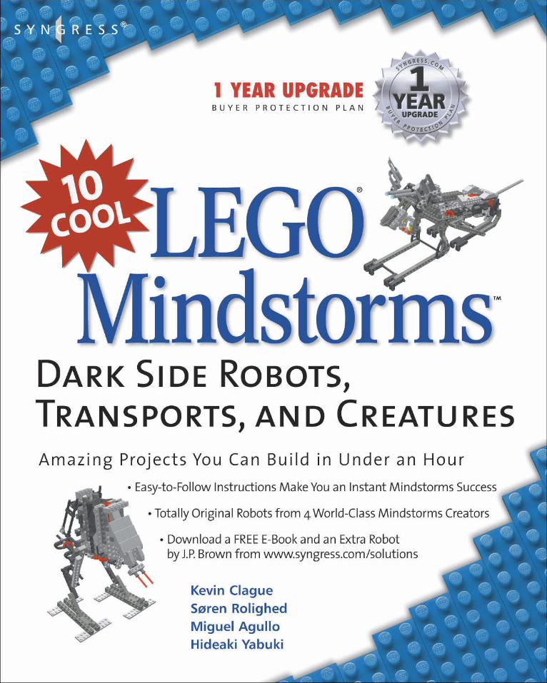
10 cool lego mindstorms: dark side robots, transports, and creatures: amazing projects you can build...
TRANSCRIPT

solutions@s y n g r e s s . c o m
With more than 1,500,000 copies of our MCSE, MCSD, CompTIA, and Ciscostudy guides in print, we continue to look for ways we can better serve theinformation needs of our readers. One way we do that is by listening.
Readers like yourself have been telling us they want an Internet-based ser-vice that would extend and enhance the value of our books. Based onreader feedback and our own strategic plan, we have created a Web sitethat we hope will exceed your expectations.
[email protected] is an interactive treasure trove of useful infor-mation focusing on our book topics and related technologies. The siteoffers the following features:
■ One-year warranty against content obsolescence due to vendorproduct upgrades. You can access online updates for any affectedchapters.
■ “Ask the Author” customer query forms that enable you to postquestions to our authors and editors.
■ Exclusive monthly mailings in which our experts provide answers toreader queries and clear explanations of complex material.
■ Regularly updated links to sites specially selected by our editors forreaders desiring additional reliable information on key topics.
Best of all, the book you’re now holding is your key to this amazing site.Just go to www.syngress.com/solutions, and keep this book handy whenyou register to verify your purchase.
Thank you for giving us the opportunity to serve your needs. And be sureto let us know if there’s anything else we can do to help you get the maximum value from your investment. We’re listening.
www.syngress.com/solutions

SYNGRESS SOLUTIONS…
so l u t i o n s @ s y n g r e s s .com
Building Robots with LEGO MINDSTORMSThe LEGO MINDSTORMS Robotics Invention System (RIS) has been called “themost creative play system ever developed.” This book unleashes the full powerand potential of the tools, bricks, and components that make up LEGO MIND-STORMS. Some of the world's leading LEGO MINDSTORMS inventors sharetheir knowledge and development secrets. You will discover an incredible rangeof ideas to inspire your next invention. This is the ultimate insider's look atLEGO MINDSTORMS and is the perfect book whether you build world-classcompetitive robots or just like to mess around for the fun of it.ISBN: 1-928994-67-9
Price: $29.95 US, $46.95 CAN
AVAILABLE NOWORDER atwww.syngress.com
Programming LEGO Mindstorms with JavaProgramming LEGO Mindstorms with Java is as much about robotics pro-gramming as it is about Java programming. This book is for all levels ofMindstorms users, from hobbyists to the serious Mindstorms aficionados. Thisbook is also appropriate for a variety of programming levels; those with onlya modicum of Java knowledge as well as those at an advanced level will findmuch to learn within these pages. You will cover all the basics of program-ming the RCX, beginning with the introduction of the available Java APIs usedto communicate remotely to the RCX using its default firm- ware, all the waythrough the advanced topics of embedded programming using a custom JavaVirtual Machine (JVM).ISBN: 1-928994-55-5
Price: $29.95 US, $46.95 CAN AVAILABLE NOW!ORDER atwww.syngress.com
More Great Books in the Syngress 10 Cool Series!The 10 Cool Series covers the most popular MINDSTORMS kits from LEGO and these books give youeverything you need to create Cool creations in under 1 hour.
AVAILABLE SEPTEMBERORDER atwww.syngress.com
10 Cool LEGO MINDSTORMS Robotics
Invention System 2 Projects
ISBN: 1-931836-61-2
Price: $24.95 US, $38.95 CAN
AVAILABLE OCTOBERORDER atwww.syngress.com
10 Cool LEGO MINDSTORMS
ULTIMATE BUILDERS PROJECTS
ISBN: 1-931836-60-4
Price: $24.95 US, $38.95 CAN
Kevin Clague Søren Rolighed Miguel Agullo Hideaki Yabuki
LLEEGGO O MMinindstdstoorrmsms
®
™
1 YEAR UPGRADEB U Y E R P R O T E C T I O N P L A N
Dark Side Robots,Transports, and Creatures
Syngress Publishing, Inc., the author(s), and any person or firm involved in the writing, editing, or production(collectively “Makers”) of this book (“the Work”) do not guarantee or warrant the results to be obtained from the Work.
There is no guarantee of any kind, expressed or implied, regarding the Work or its contents. The Work is sold AS ISand WITHOUT WARRANTY. You may have other legal rights, which vary from state to state.
In no event will Makers be liable to you for damages, including any loss of profits, lost savings, or other incidentalor consequential damages arising out from the Work or its contents. Because some states do not allow the exclusionor limitation of liability for consequential or incidental damages, the above limitation may not apply to you.
You should always use reasonable care, including backup and other appropriate precautions, when working withcomputers, networks, data, and files.
Syngress Media®, Syngress®, “Career Advancement Through Skill Enhancement®,” “Hack Proofing®,” and “Ask theAuthor UPDATE®,” are registered trademarks of Syngress Publishing, Inc. “Mission Critical™,” and “The Only Way toStop a Hacker is to Think Like One™” are trademarks of Syngress Publishing, Inc. Brands and product namesmentioned in this book are trademarks or service marks of their respective companies.
QuickTime and the QuickTime logo are trademarks used under license. The QuickTime logo is registered in the U.S.and other countries.
KEY SERIAL NUMBER001 T945G3ERT5002 T4K9PLDLE4003 L3N5SPT64N004 B39SH5J74N005 U6N6Y3KM7H006 N2VN9G4RC7007 TU8B2BVH3W008 9R5MQPBR5A009 M483N546HA010 H2Q7SGT6YS
PUBLISHED BYSyngress Publishing, Inc.800 Hingham StreetRockland, MA 02370
10 Cool LEGO MINDSTORMS Dark Side Robots
Copyright © 2002 by Syngress Publishing, Inc. All rights reserved. Printed in the United States of America. Except aspermitted under the Copyright Act of 1976, no part of this publication may be reproduced or distributed in any formor by any means, or stored in a database or retrieval system, without the prior written permission of the publisher,with the exception that the program listings may be entered, stored, and executed in a computer system, but theymay not be reproduced for publication.
Printed in the United States of America
1 2 3 4 5 6 7 8 9 0
ISBN: 1–931836–59–0
Acquisitions Editor: Jonathan Babcock Cover Designer: Michael KavishCopy Editor: Kate Glennon Page Layout and Art by: Shannon Tozier
Distributed by Publishers Group West in the United States and Jaguar Book Group in Canada.

v
Syngress Acknowledgments
We would like to acknowledge the following people for their kindness and support inmaking this book possible.
A special thanks to Matt Gerber at Brickswest for his help and support for our books.
Karen Cross, Lance Tilford, Meaghan Cunningham, Kim Wylie, Harry Kirchner, Kevin Votel,Kent Anderson, Frida Yara, Jon Mayes, John Mesjak, Peg O’Donnell, Sandra Patterson, BettyRedmond, Roy Remer, Ron Shapiro, Patricia Kelly, Andrea Tetrick, Jennifer Pascal, Doug Reil,David Dahl, Janis Carpenter, and Susan Fryer of Publishers Group West for sharing theirincredible marketing experience and expertise.
Jacquie Shanahan, AnnHelen Lindeholm, David Burton, Febea Marinetti, and Rosie Moss ofElsevier Science for making certain that our vision remains worldwide in scope.
David Buckland, Wendi Wong, Marie Chieng, Lucy Chong, Leslie Lim, Audrey Gan, andJoseph Chan of Transquest Publishers for the enthusiasm with which they receive our books.
Kwon Sung June at Acorn Publishing for his support.
Jackie Gross, Gayle Voycey, Alexia Penny, Anik Robitaille, Craig Siddall, Darlene Morrow,Iolanda Miller, Jane Mackay, and Marie Skelly at Jackie Gross & Associates for all their helpand enthusiasm representing our product in Canada.
Lois Fraser, Connie McMenemy, Shannon Russell, and the rest of the great folks at JaguarBook Group for their help with distribution of Syngress books in Canada.
A special welcome to the folks at Woodslane in Australia! Thank you to David Scott andeveryone there as we start selling Syngress titles through Woodslane in Australia, NewZealand, Papua New Guinea, Fiji Tonga, Solomon Islands, and the Cook Islands.
The Syngress Production Department would like to thank Vesna Williams, Sasha Williams,and Kevin Cawley for all of their hard work on this project.

vii
Hideaki Yabuki works as a Media Activist promoting new technologies to thenext generation. To him, robotics is the most important of these technologies. Hewas first introduced to LEGO robots in 1985 by a friend of his, Mr. Kurita, whohad recently returned from the MIT Media Lab with some LEGO Dacta products.Influenced also by Dr. Seymour Papert’s book, Mindstorms: Children, Computers,and Powerful Ideas, Hideaki feels that LEGOs offer a hands-on approach tolearning that is often missing these days in our digital world. His robot in thisbook, the Scorpion, is the result of much trial and error on his part. Hideakiwould like to thank J.P. Brown, without whom he could not have becomeinvolved with this book. He would also like to thank Kevin Clague, inventor ofthe LPub application for semi-automated LEGO instruction creation. Lastly,Hideaki would like to give his deepest thanks for the support of his mother, Rei,and his dear wife and son, Keiko and Kei. Hideaki has a dream that one day thepeople of Japan will be able to join hands with biped robots as friends.
Kevin Clague graduated in 1983 from Iowa State University with a bachelor’s ofScience degree in Computer Engineering. For the past 18 years, Kevin has workedas a Diagnostic Engineer at the Amdahl Corporation. For the last two years, he hasalso acted as a Senior Staff Engineer doing verification work at Sun Microsystemson their Ultra-Sparc V RISC processor. Kevin has two major hobbies: theatricallighting and LEGO MINDSTORMS. Kevin has been playing with the RIS 1.5 forseveral years now and is currently working on LPub, an application to revolu-tionize the world of creating online LEGO building instructions.
Miguel Agullo was born in Spain but has lived abroad for long periods of time,from the Far East to South America, from central Europe to the U.S. His widerange of interests is responsible for his work in such diverse industries asfinance, media, aeronautics, and antique trading. Trained as a journalist andimpressed with the candor and resourcefulness of the online LEGO community,Miguel tries to give something back by regularly updating his Web site atwww.geocities.com/technicpuppy with instructions for new models, new Ldrawpieces, and anything he thinks is worth sharing with other LEGO aficionados.His building interests revolve around robotics, and specifically biomechanics: cre-ating mechanisms that mimic the behavior of natural devices such as legs orarms. His creations include biped walkers, robots that jump, and a fully func-tional (including a brake!) LEGO motorcycle. His current hobbies include
Contributors
viii
boating, biking, traveling and learning Thai and Dutch (his wife is Thai and theylive in Amsterdam, which explains the bike and the boat).
Søren Rolighed is a data warehouse consultant, working on building and main-taining databases for telco-data in the largest data warehouse in Denmark. Likealmost all Danish kids, he started playing with LEGO at an early age. As anadult he has continued with his passion for LEGOs, and the introduction of theLEGO Technics and LEGO MINDSTORMS kits opened up a whole new world ofpossibilities! Søren enjoys building LEGO Mindstorm robots and programmingthem with his computer. He would like to thank his three great children, Emma,Oscar, and Victor, for their patience and understanding when dad has to requisi-tion all of their interesting motors, gears, and special parts for his own LEGOcreations. Søren and his family live in Copenhagen, Denmark.
J.P. Brown is a Consultant Environmental Conservator who has worked on suchhistorical sites as Independence Hall, Philadelphia, PA and George Washington’smansion, Mount Vernon, VA. He first became interested in LEGO MINDSTORMSin July 1999, but his interest did not really take off until he discovered DaveBaum’s Not Quite C (NQC) programming environment for the RCX brick laterthat year. He quickly became involved as a moderator for LEGO MINDSTORMSforums on the Web, and was later selected by LEGO as a preview builder for theMINDSTORMS Vision Command system (along with Søren Rolighed and severalothers). His robot, Biped II, won the February 2001 MINDSTORMS Hall of Fame,Special Competition, but he is perhaps best known for his Rubik’s Cube solvingrobot, CubeSolver, which was featured in the New York Times in October 2001and other papers around the world.
ix
Contents
Foreword xi
Robot 1 Super Battle Droid 1
Robot 2 Orbital Defense Cannon 23
Robot 3 Imperial AT-ST 55
Robot 4 Go-Rilla 79
Robot 5 X-Stormer 95
Robot 6 Droid Transporter 119
Robot 7 Draigon 145
Robot 8 Scorpion Assassin Droid 159
Robot 9 Ludic Ordinance Unit (LOU) 179
Robot 10 Imperial Hound 215
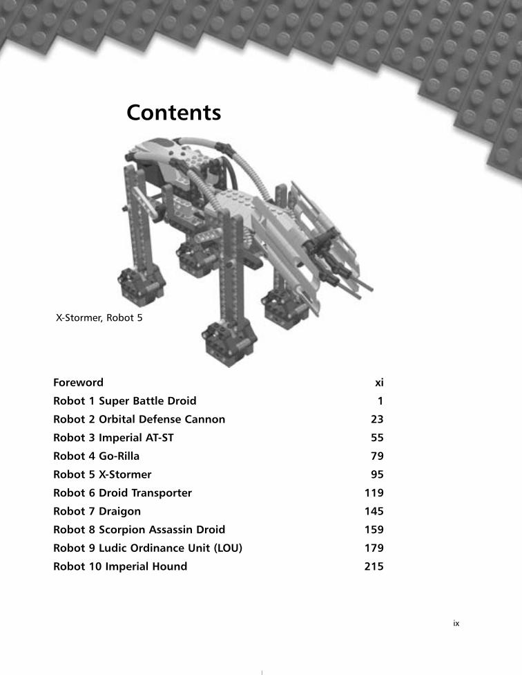
X-Stormer, Robot 5

Foreword
xi
This book is the result of a lifetime exploring the world of LEGO. As a kid, Iloved taking mechanical things apart to figure out how they worked, theneither putting them back together or using the parts to invent something new,so I really enjoyed playing with LEGOs—despite the fact that the things I builtoften fell apart! Eventually, though, I grew out of them. Several years after Igrew out of this first LEGO phase, LEGO introduced the TECHNIC line ofLEGOs, a superior set of building parts allowing sturdy structures and compli-cated designs with gears, levers, and all kinds of moving mechanics, and thenintroduced the MINDSTORMS line. Two and a half years ago, my wife got methe LEGO MINDSTORMS Dark Side Developer Kit for Christmas—I immedi-ately built the AT-AT walker and was hooked on LEGOs all over again. A fewmonths later, I went out and got the Robot Invention System 1.5, and thusbegan my second LEGO phase. LEGO’s TECHNIC and MINDSTORMS kitshave allowed me to pursue both my passion for building with LEGOs and myinterest in all things mechanical.
This book is a first for my co-authors, Syngress, and myself. I’ve reallyenjoyed working with and getting to know the other authors (and the people atSyngress) during the development of this book. The Internet has allowedSyngress to gather a team of authors from many different countries, includingBritain, Holland, Denmark, Japan, and the United States. Before I beganworking on the book, I’d met J.P. Brown in person when he was doing someconsulting work in St. Paul, Minnesota. I’d also had some contact with MiguelAgullo (a.k.a. “Technic Puppy”) because he runs a Web page dedicated specifi-cally to LEGO biped robots, which are my favorite type of robot to invent. I’dheard of Soren Rolighed because he made it into the LEGO MINDSTORMSHall of Fame, and I’d also heard of Hideaki Yabuki (a.k.a. “Joda”, which is
Japanese for Yoda) because I saw one of his fabulous grabber arms featured onthe LEGO MINDSTORMS Web site.
When Jonathan Babcock at Syngress first contacted me about working on10 Cool LEGO MINDSTORMS Dark Side Robots, Transports, and Creatures, hetold me it was going to be a step-by-step building instruction book. I wascurious how we were going to lay out all the artwork for the book, andSyngress didn’t initially have a firm plan on how this would be done. Aftertalking it out with Jonathan, it was decided that I would write some tools tohelp do the job. Many tools had already been developed by others and givenaway over the Internet for the LEGO community to share. I know that withoutthose tools this book would never have made it to press as polished and asquickly as it has.
The groundwork for all the tools used was laid out by the late JamesJessiman. James created the LDraw program on which all the other tools arebased. MLCad, written by Michael Lachmann, is a second-generation computeraided design (CAD) program that is used to enter robotic designs. The thirdtool that we use is L3P, written by Lars C. Hassing. L3P converts LDraw files toPOV-Ray files. POV-Ray is the program that produces the final images that yousee in this book. POV-Ray has a long history of contributors. The Windows ver-sion we used was coordinated by Chris Cason.
I wrote a program called LPub for this book that combines all these toolstogether to generate the step-by-step construction images and the correspondingpart-list images. The development of LPub has been an adventure in and ofitself, and has kept me very busy over the past several months. I will becleaning it up, making it more robust, and making it available for all to use inthe near future.
I hope you enjoy building the robots in this book—some very creativeminds have done some amazing work inventing the robots you’ll find here. Weencourage you to use your own creativity to modify our designs after you’vebuilt some of them, in the true LEGO building tradition.
If you like this book—and I think you will—be sure to look for two similarbooks that Syngress will be putting out in the near future: 10 Cool LEGOMINDSTORMS Robotics Invention System 2.0 Projects: Amazing Projects YouCan Build in Under an Hour (ISBN 1-931836-61-2) and 10 Cool LEGO MIND-STORMS Ultimate Builders Projects: Amazing Projects You Can Build in Underan Hour (ISBN 1-931836-60-4).
—Kevin L. Clague
Foreword
xii
Robot 1
1
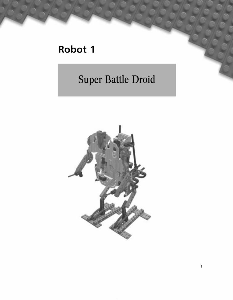
Super Battle Droid
In Episode II: Attack of the Clones, the evil Sith lord Darth Sidious headed aseparatist movement in the Republic, with the nefarious goal of ruling theentire galaxy. Darth Sideous had turned Jedi Knight Count Dooku to the darkside, and used him to lead the separatist movement. The Techno Union, one ofthe members of the separatist movement, created an army of Super BattleDroids, which were more powerful and aggressive than the Battle Droids usedby the Trade Federation in Episode 1: The Phantom Menace.
We first heard of the Clone Wars in Episode IV: A New Hope, when LukeSkywalker and old Ben Kenobi (Obi-Wan) were talking about Luke’s father. InEpisode II, on the planet Geonosis, we see the start of the Clone Wars, as theJedi Knights wage war with the Battle Droid and Super Battle Droid army torescue Senator Amadala, Jedi Knight Obi-Wan Kenobi, and his Padawan,Anakin Skywalker.
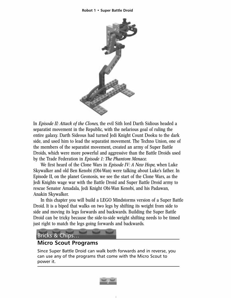
In this chapter you will build a LEGO Mindstorms version of a Super BattleDroid. It is a biped that walks on two legs by shifting its weight from side toside and moving its legs forwards and backwards. Building the Super BattleDroid can be tricky because the side-to-side weight shifting needs to be timedjust right to match the legs going forwards and backwards.
Bricks & Chips…Micro Scout ProgramsSince Super Battle Droid can walk both forwards and in reverse, youcan use any of the programs that come with the Micro Scout topower it.
Robot 1 • Super Battle Droid
2
Robot 1 • Super Battle Droid
3
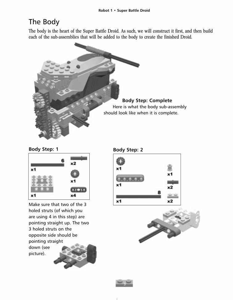
The BodyThe body is the heart of the Super Battle Droid. As such, we will construct it first, and then buildeach of the sub-assemblies that will be added to the body to create the finished Droid.
Body Step: 1
Make sure that two of the 3holed struts (of which youare using 4 in this step) arepointing straight up. The two3 holed struts on theopposite side should bepointing straight down (see picture).
Body Step: CompleteHere is what the body sub-assembly
should look like when it is complete.
Body Step: 2
Robot 1 • Super Battle Droid
4
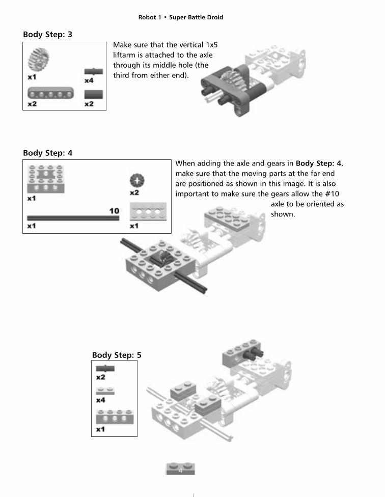
Body Step: 3Make sure that the vertical 1x5liftarm is attached to the axlethrough its middle hole (the third from either end).
Body Step: 4When adding the axle and gears in Body Step: 4,make sure that the moving parts at the far endare positioned as shown in this image. It is alsoimportant to make sure the gears allow the #10
axle to be oriented asshown.
Body Step: 5
Robot 1 • Super Battle Droid
5
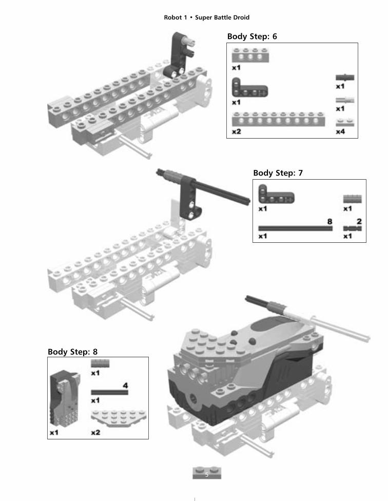
Body Step: 7
Body Step: 8
Body Step: 6
Robot 1 • Super Battle Droid
6
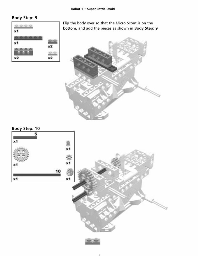
Body Step: 9Flip the body over so that the Micro Scout is on thebottom, and add the pieces as shown in Body Step: 9
Body Step: 10
Robot 1 • Super Battle Droid
7
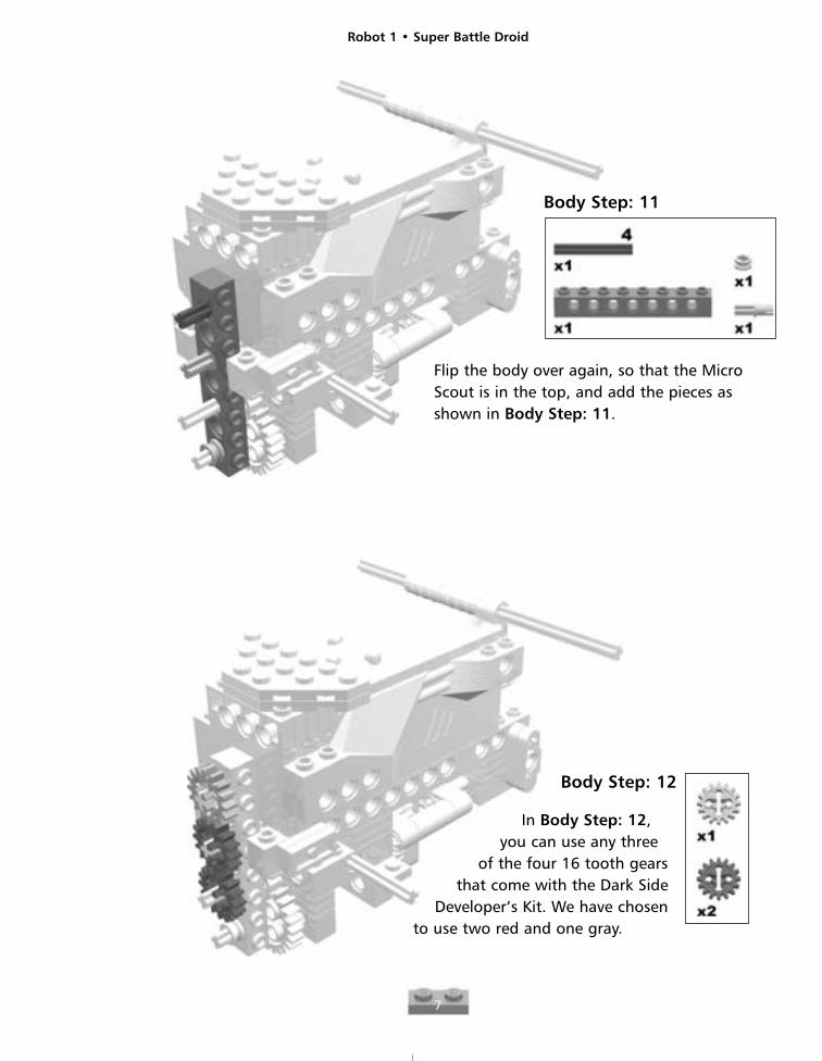
Body Step: 11
Flip the body over again, so that the MicroScout is in the top, and add the pieces asshown in Body Step: 11.
Body Step: 12
In Body Step: 12,you can use any three
of the four 16 tooth gearsthat come with the Dark Side
Developer’s Kit. We have chosen to use two red and one gray.
Robot 1 • Super Battle Droid
8
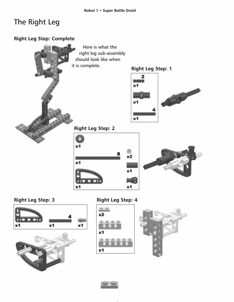
The Right Leg
Right Leg Step: Complete
Right Leg Step: 1
Right Leg Step: 2
Right Leg Step: 3 Right Leg Step: 4
Here is what theright leg sub-assembly
should look like when it is complete.

Robot 1 • Super Battle Droid
9
Right Leg Step: 5
Right Leg Step: 6 Right Leg Step: 7
Robot 1 • Super Battle Droid
10
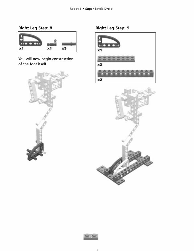
Right Leg Step: 8
You will now begin constructionof the foot itself.
Right Leg Step: 9
Robot 1 • Super Battle Droid
11
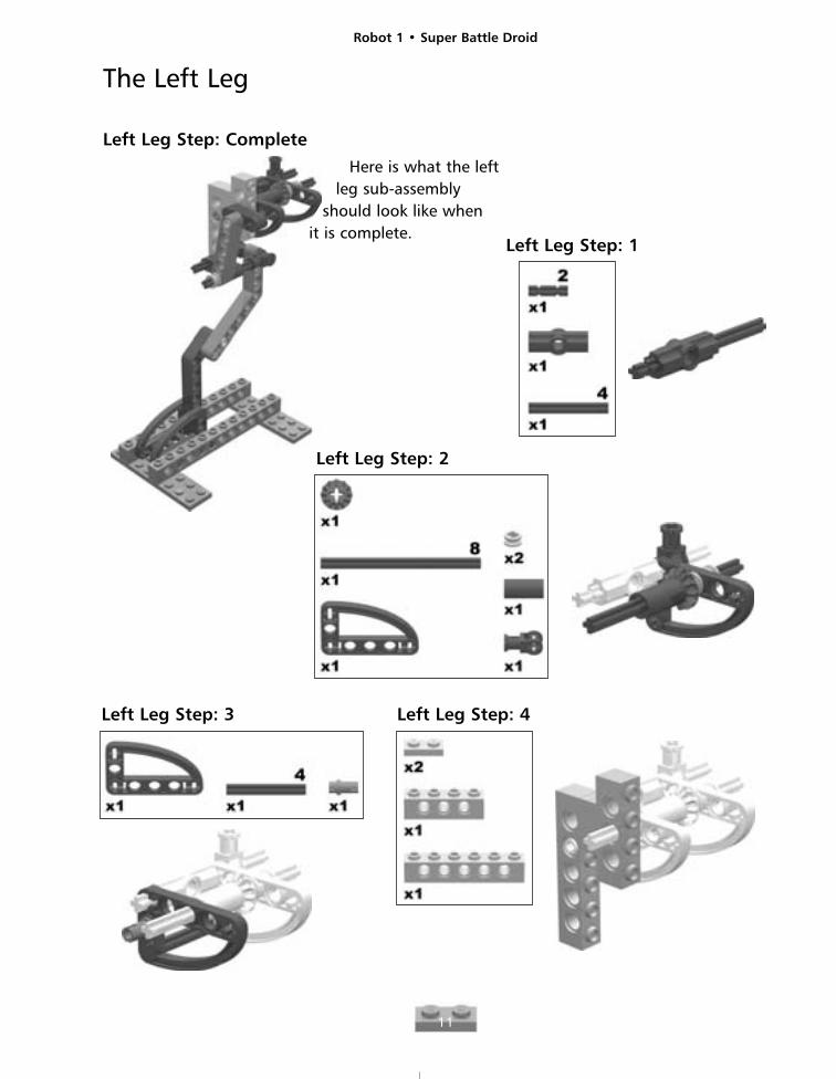
The Left Leg
Left Leg Step: Complete
Here is what the leftleg sub-assembly
should look like when it is complete.
Left Leg Step: 1
Left Leg Step: 2
Left Leg Step: 3 Left Leg Step: 4
Robot 1 • Super Battle Droid
12
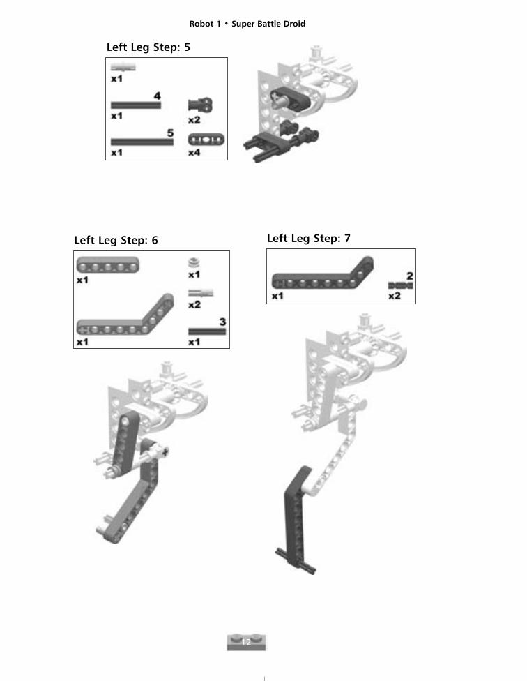
Left Leg Step: 5
Left Leg Step: 6 Left Leg Step: 7
Robot 1 • Super Battle Droid
13
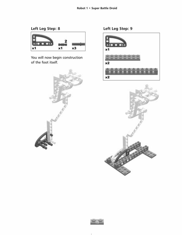
Left Leg Step: 8
You will now begin constructionof the foot itself.
Left Leg Step: 9
Robot 1 • Super Battle Droid
14
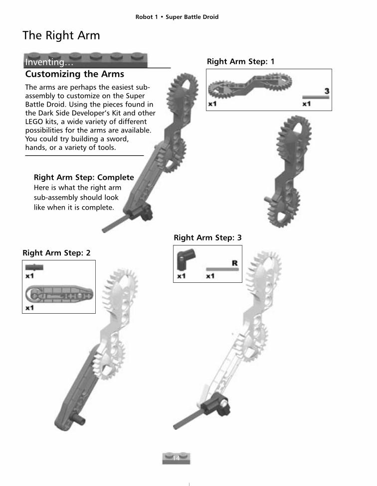
Right Arm Step: CompleteHere is what the right armsub-assembly should looklike when it is complete.
Right Arm Step: 1
Right Arm Step: 2
Right Arm Step: 3
The Right Arm
Inventing…Customizing the ArmsThe arms are perhaps the easiest sub-assembly to customize on the SuperBattle Droid. Using the pieces found inthe Dark Side Developer’s Kit and otherLEGO kits, a wide variety of differentpossibilities for the arms are available.You could try building a sword,hands, or a variety of tools.
Robot 1 • Super Battle Droid
15
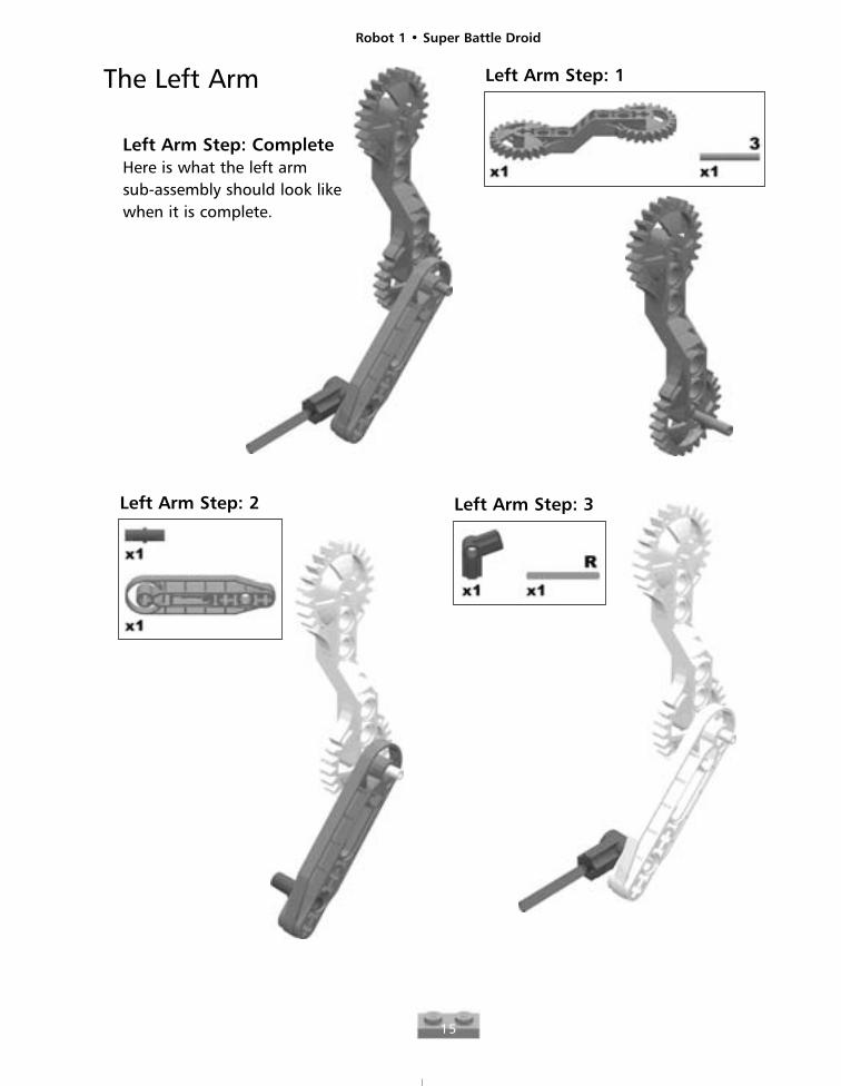
Left Arm Step: CompleteHere is what the left arm sub-assembly should look likewhen it is complete.
Left Arm Step: 1
Left Arm Step: 2 Left Arm Step: 3
The Left Arm
Robot 1 • Super Battle Droid
16
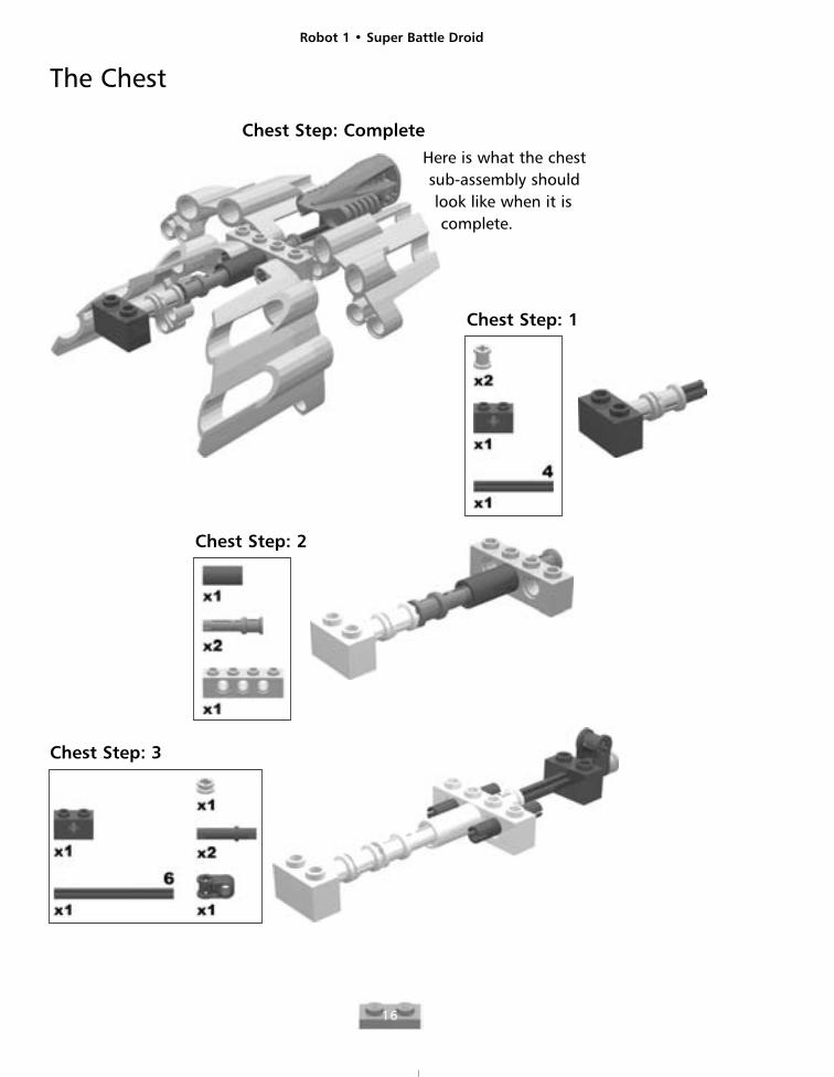
The Chest
Chest Step: Complete
Here is what the chestsub-assembly shouldlook like when it iscomplete.
Chest Step: 1
Chest Step: 3
Chest Step: 2
Robot 1 • Super Battle Droid
17
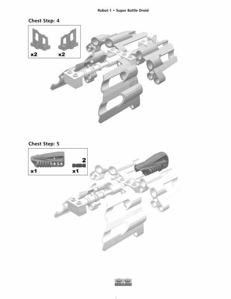
Chest Step: 4
Chest Step: 5
Robot 1 • Super Battle Droid
18
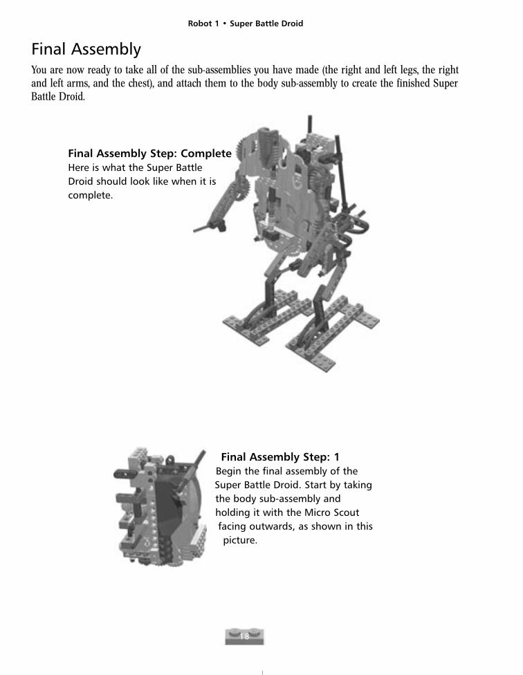
Final Assembly Step: CompleteHere is what the Super Battle Droid should look like when it iscomplete.
Final Assembly Step: 1Begin the final assembly of theSuper Battle Droid. Start by takingthe body sub-assembly andholding it with the Micro Scoutfacing outwards, as shown in thispicture.
Final AssemblyYou are now ready to take all of the sub-assemblies you have made (the right and left legs, the rightand left arms, and the chest), and attach them to the body sub-assembly to create the finished SuperBattle Droid.
Robot 1 • Super Battle Droid
19
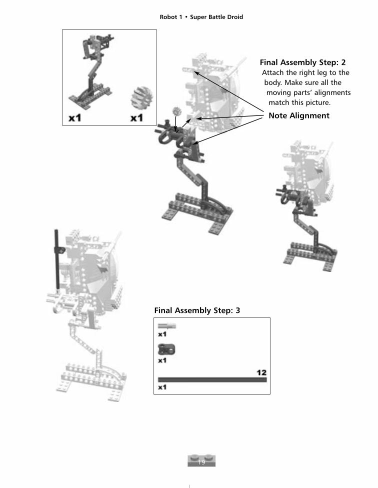
Final Assembly Step: 3
Final Assembly Step: 2Attach the right leg to thebody. Make sure all themoving parts’ alignmentsmatch this picture.
Note Alignment
Robot 1 • Super Battle Droid
20
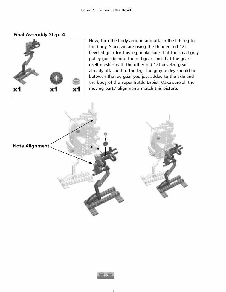
Note Alignment
Final Assembly Step: 4Now, turn the body around and attach the left leg tothe body. Since we are using the thinner, red 12tbeveled gear for this leg, make sure that the small graypulley goes behind the red gear, and that the gearitself meshes with the other red 12t beveled gearalready attached to the leg. The gray pulley should bebetween the red gear you just added to the axle andthe body of the Super Battle Droid. Make sure all themoving parts’ alignments match this picture.
Robot 1 • Super Battle Droid
21
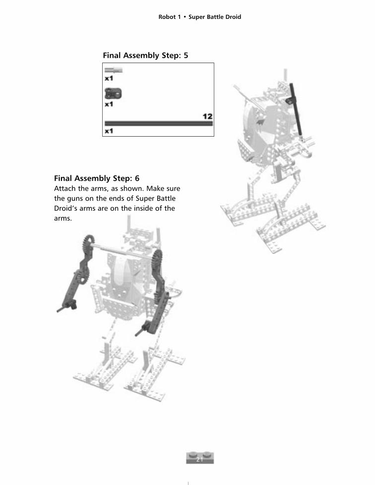
Final Assembly Step: 5
Final Assembly Step: 6Attach the arms, as shown. Make surethe guns on the ends of Super BattleDroid’s arms are on the inside of thearms.
Robot 1 • Super Battle Droid
22
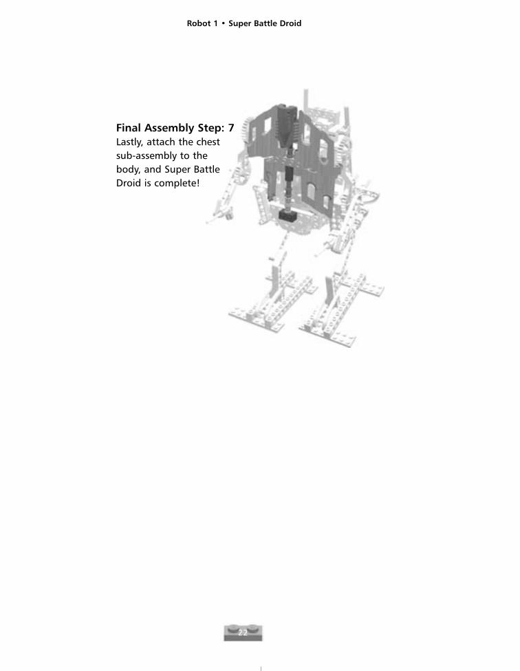
Final Assembly Step: 7Lastly, attach the chestsub-assembly to thebody, and Super BattleDroid is complete!
Robot 2
23
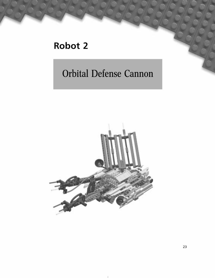
Orbital Defense Cannon
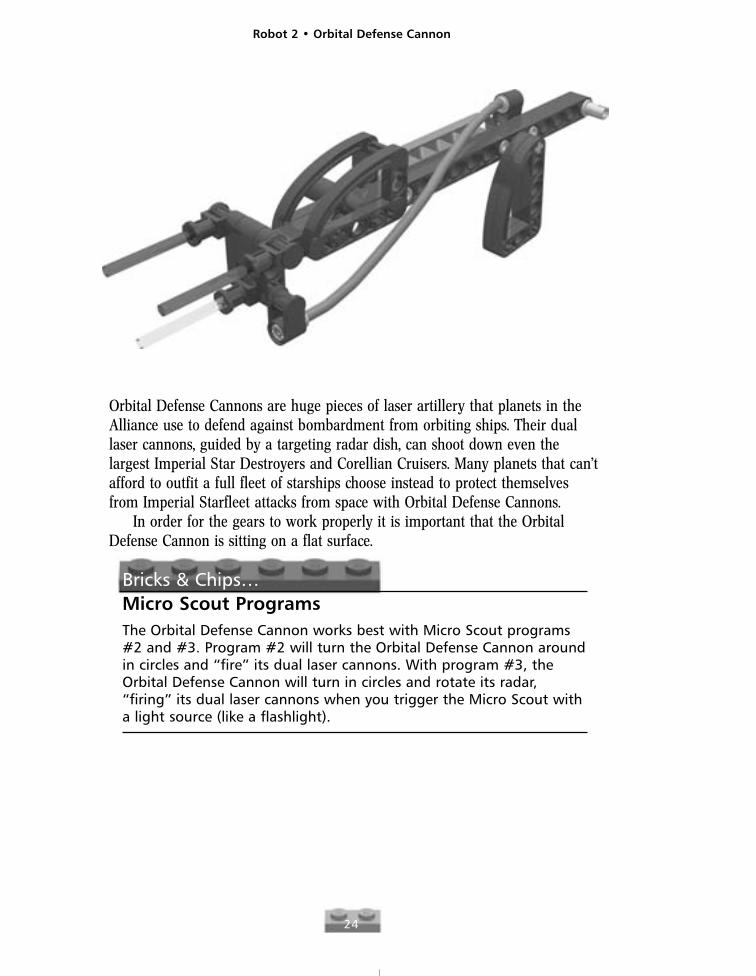
Orbital Defense Cannons are huge pieces of laser artillery that planets in theAlliance use to defend against bombardment from orbiting ships. Their duallaser cannons, guided by a targeting radar dish, can shoot down even thelargest Imperial Star Destroyers and Corellian Cruisers. Many planets that can’tafford to outfit a full fleet of starships choose instead to protect themselvesfrom Imperial Starfleet attacks from space with Orbital Defense Cannons.
In order for the gears to work properly it is important that the OrbitalDefense Cannon is sitting on a flat surface.
Bricks & Chips…Micro Scout ProgramsThe Orbital Defense Cannon works best with Micro Scout programs#2 and #3. Program #2 will turn the Orbital Defense Cannon aroundin circles and “fire” its dual laser cannons. With program #3, theOrbital Defense Cannon will turn in circles and rotate its radar,“firing” its dual laser cannons when you trigger the Micro Scout witha light source (like a flashlight).
Robot 2 • Orbital Defense Cannon
24
Robot 2 • Orbital Defense Cannon
25
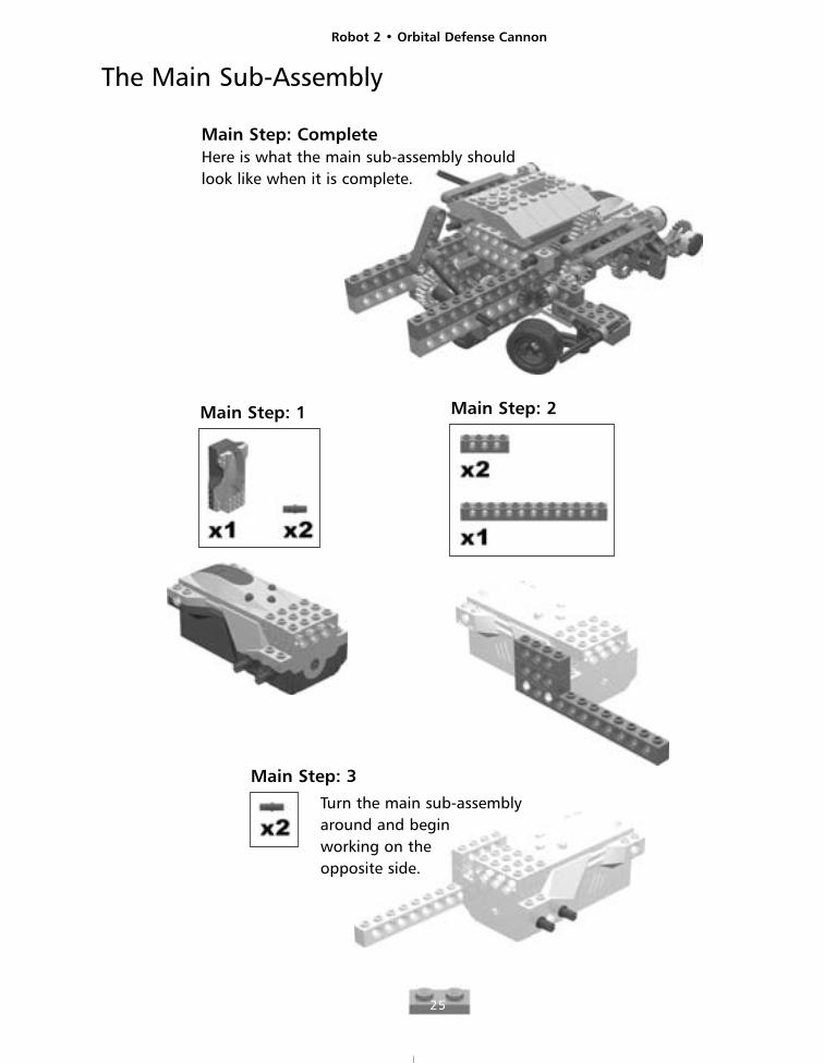
The Main Sub-Assembly
Here is what the main sub-assembly shouldlook like when it is complete.
Main Step: 1 Main Step: 2
Main Step: 3
Main Step: Complete
Turn the main sub-assemblyaround and beginworking on theopposite side.
Robot 2 • Orbital Defense Cannon
26
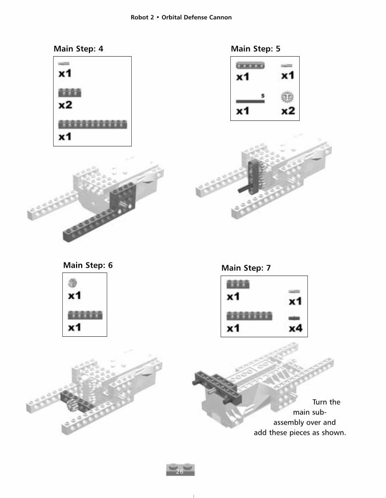
Main Step: 4 Main Step: 5
Main Step: 6 Main Step: 7
Turn themain sub-
assembly over andadd these pieces as shown.
Robot 2 • Orbital Defense Cannon
27
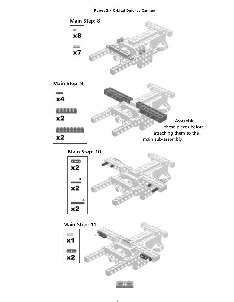
Main Step: 8
Main Step: 9
Assemblethese pieces before
attaching them to themain sub-assembly.
Main Step: 10
Main Step: 11

Robot 2 • Orbital Defense Cannon
28
Main Step: 12
Main Step: 13
Main Step: 14
Main Step: 15
Robot 2 • Orbital Defense Cannon
29
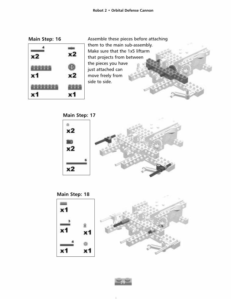
Main Step: 16 Assemble these pieces before attachingthem to the main sub-assembly.Make sure that the 1x5 liftarmthat projects from betweenthe pieces you havejust attached canmove freely fromside to side.
Main Step: 17
Main Step: 18
Robot 2 • Orbital Defense Cannon
30
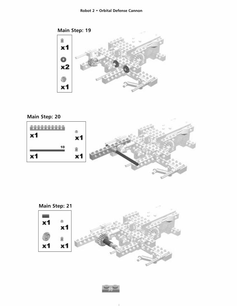
Main Step: 19
Main Step: 20
Main Step: 21

Robot 2 • Orbital Defense Cannon
31
Main Step: 22Assemble these piecesbefore attaching them to the main sub-assembly.
Main Step: 23 Assemble these piecesbefore attachingthem to the mainsub-assembly.
Main Step: 24
Robot 2 • Orbital Defense Cannon
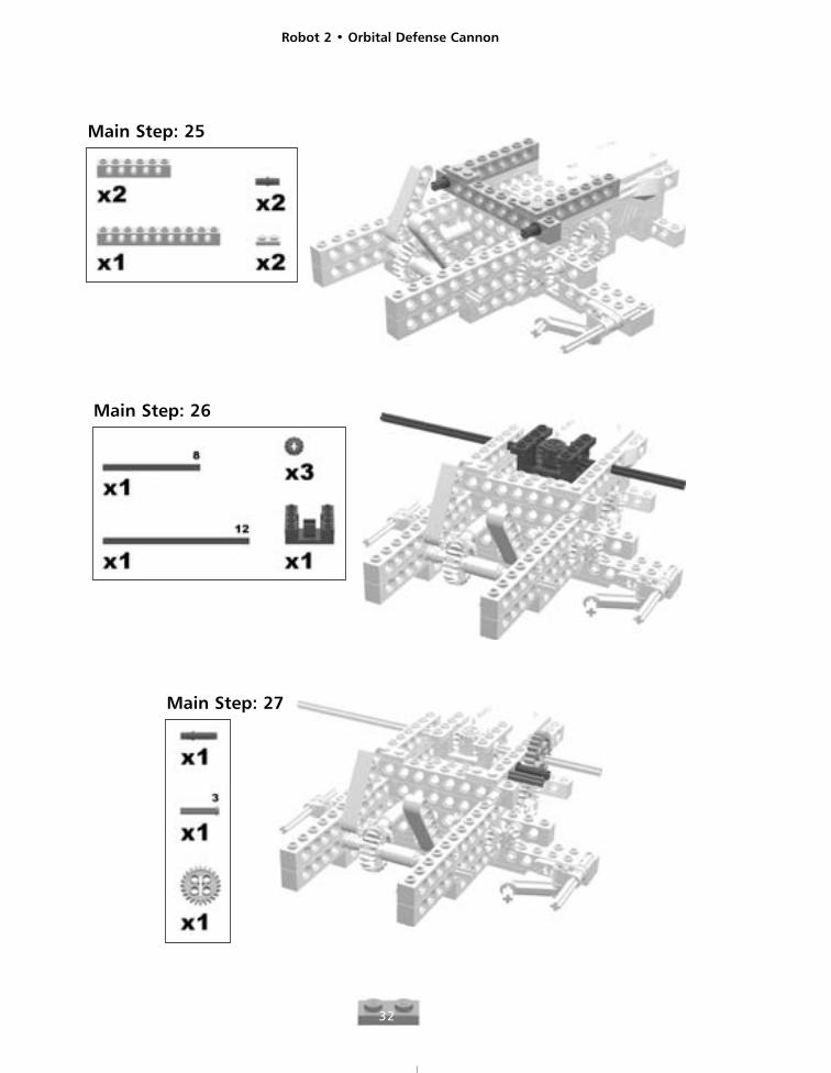
32
Main Step: 25
Main Step: 26
Main Step: 27
Robot 2 • Orbital Defense Cannon
33
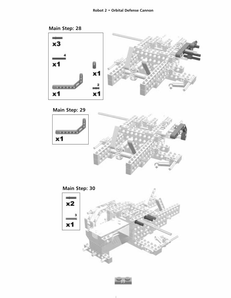
Main Step: 28
Main Step: 29
Main Step: 30
Robot 2 • Orbital Defense Cannon
34
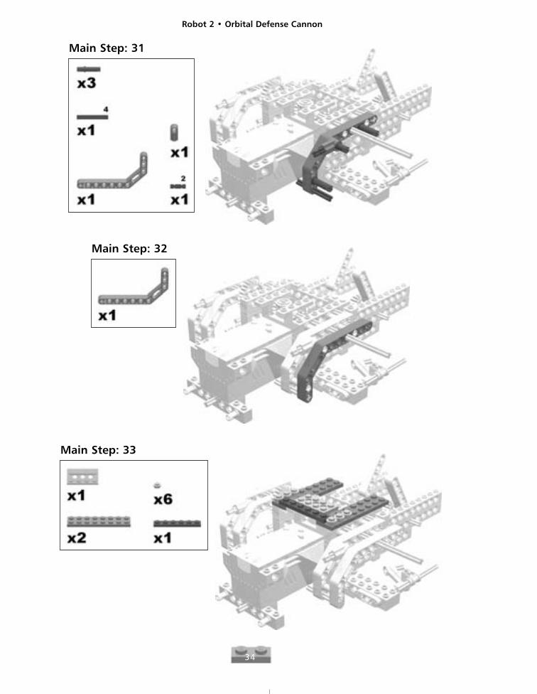
Main Step: 31
Main Step: 32
Main Step: 33
Robot 2 • Orbital Defense Cannon
35
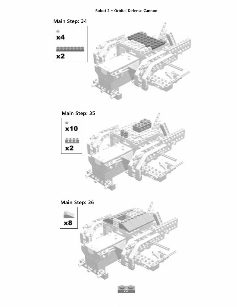
Main Step: 34
Main Step: 35
Main Step: 36
Robot 2 • Orbital Defense Cannon
36
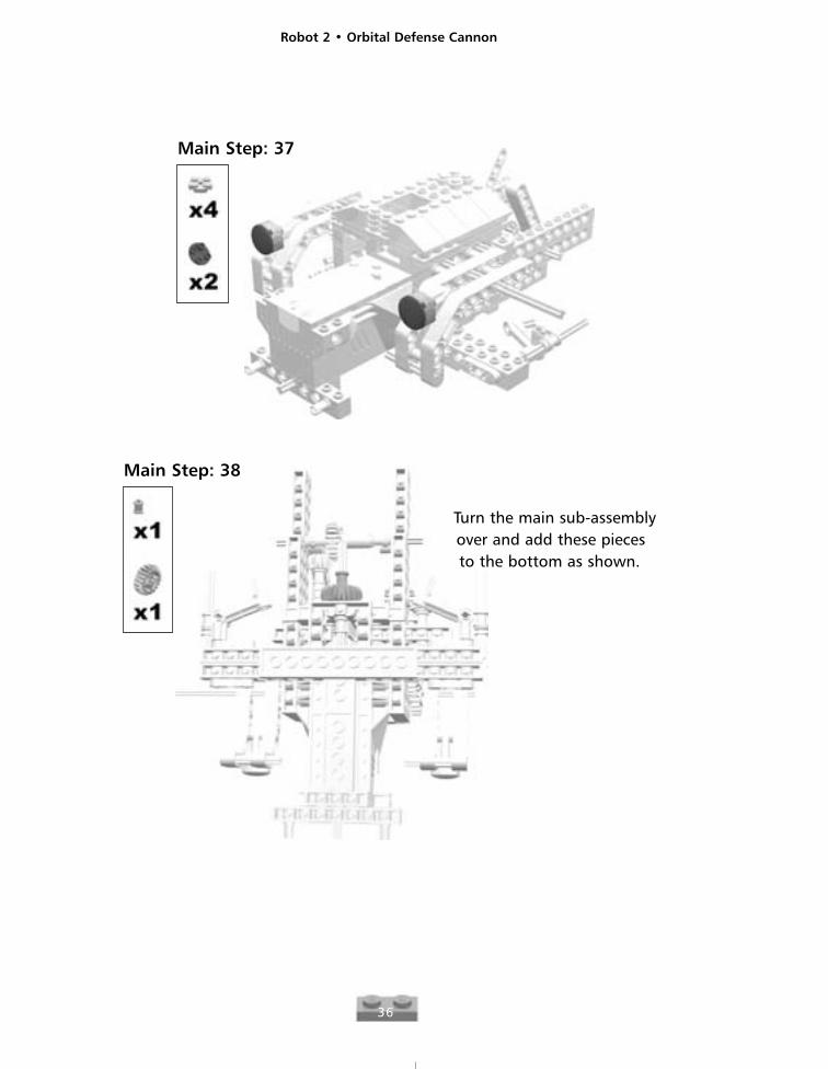
Main Step: 37
Main Step: 38
Turn the main sub-assemblyover and add these piecesto the bottom as shown.
Robot 2 • Orbital Defense Cannon
37
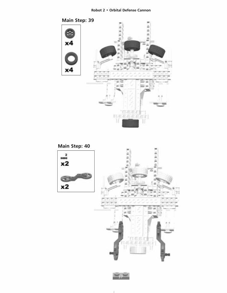
Main Step: 39
Main Step: 40
Robot 2 • Orbital Defense Cannon
38
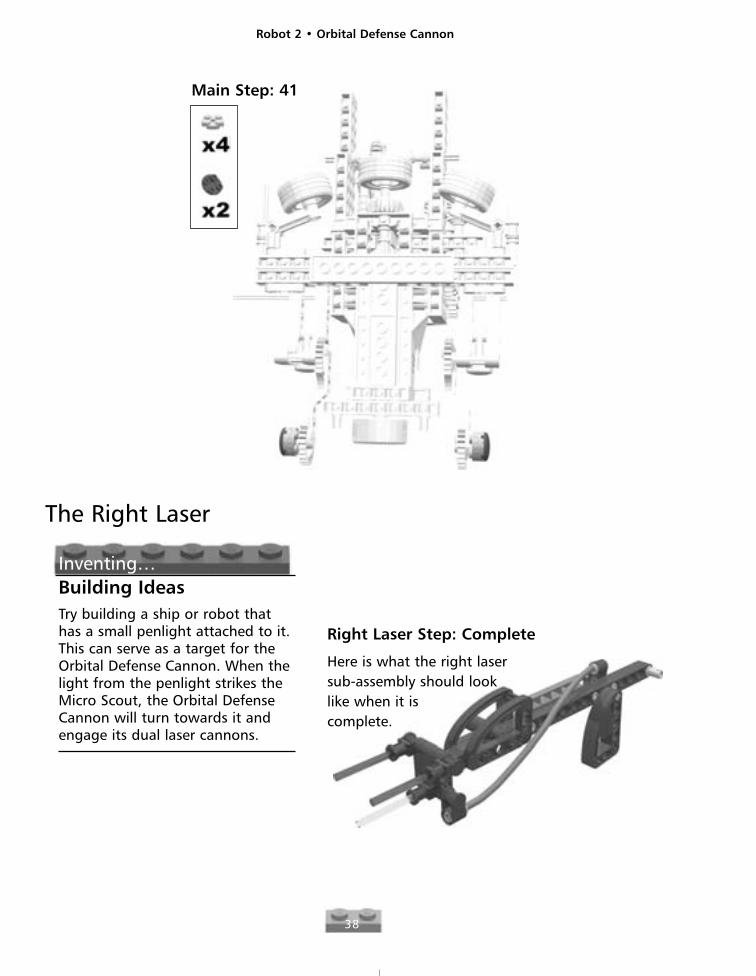
Main Step: 41
The Right Laser
Inventing…Building IdeasTry building a ship or robot thathas a small penlight attached to it.This can serve as a target for theOrbital Defense Cannon. When thelight from the penlight strikes theMicro Scout, the Orbital DefenseCannon will turn towards it andengage its dual laser cannons.
Right Laser Step: Complete
Here is what the right lasersub-assembly should looklike when it iscomplete.
Robot 2 • Orbital Defense Cannon
39
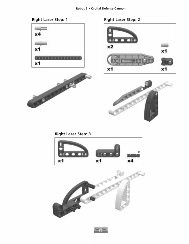
Right Laser Step: 1 Right Laser Step: 2
Right Laser Step: 3
Robot 2 • Orbital Defense Cannon
40
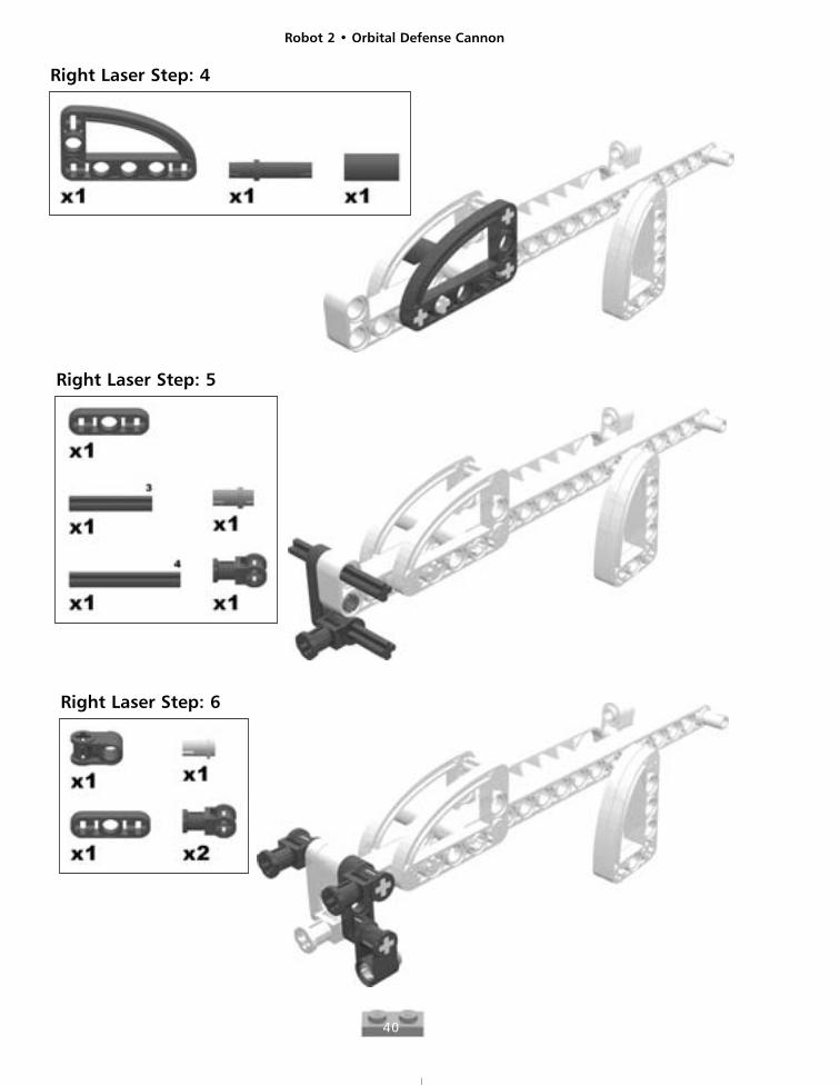
Right Laser Step: 4
Right Laser Step: 5
Right Laser Step: 6
Robot 2 • Orbital Defense Cannon
41
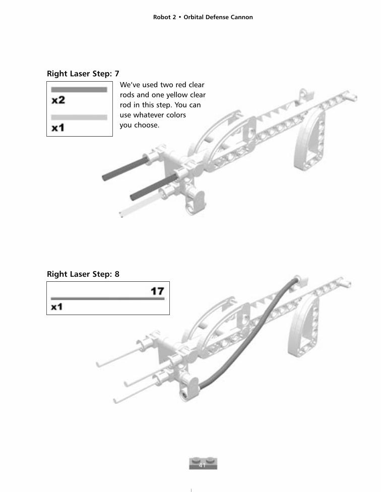
Right Laser Step: 7We’ve used two red clearrods and one yellow clearrod in this step. You canuse whatever colorsyou choose.
Right Laser Step: 8
Robot 2 • Orbital Defense Cannon
42
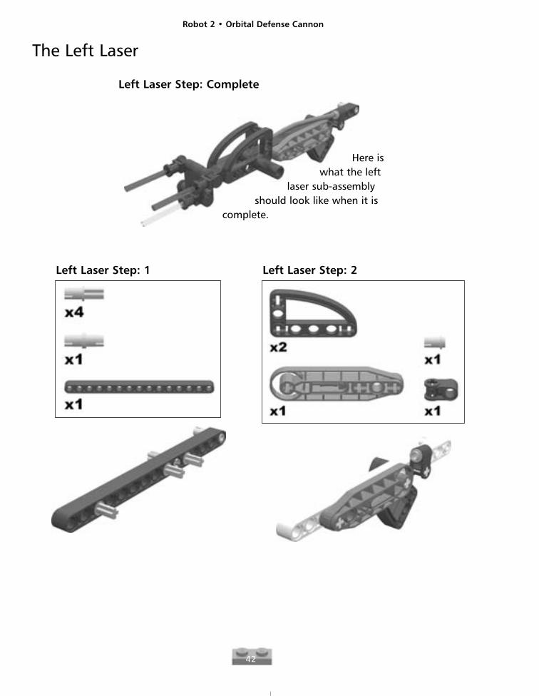
Left Laser Step: Complete
The Left Laser
Here iswhat the left
laser sub-assemblyshould look like when it is
complete.
Left Laser Step: 1 Left Laser Step: 2
Robot 2 • Orbital Defense Cannon
43
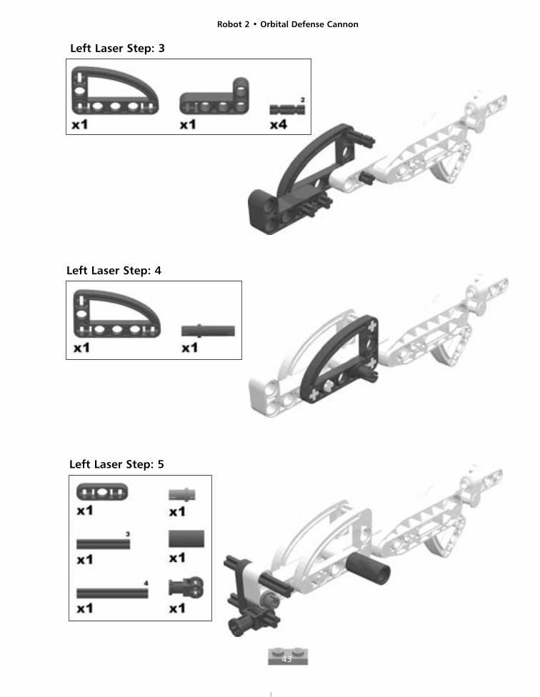
Left Laser Step: 3
Left Laser Step: 4
Left Laser Step: 5
Robot 2 • Orbital Defense Cannon
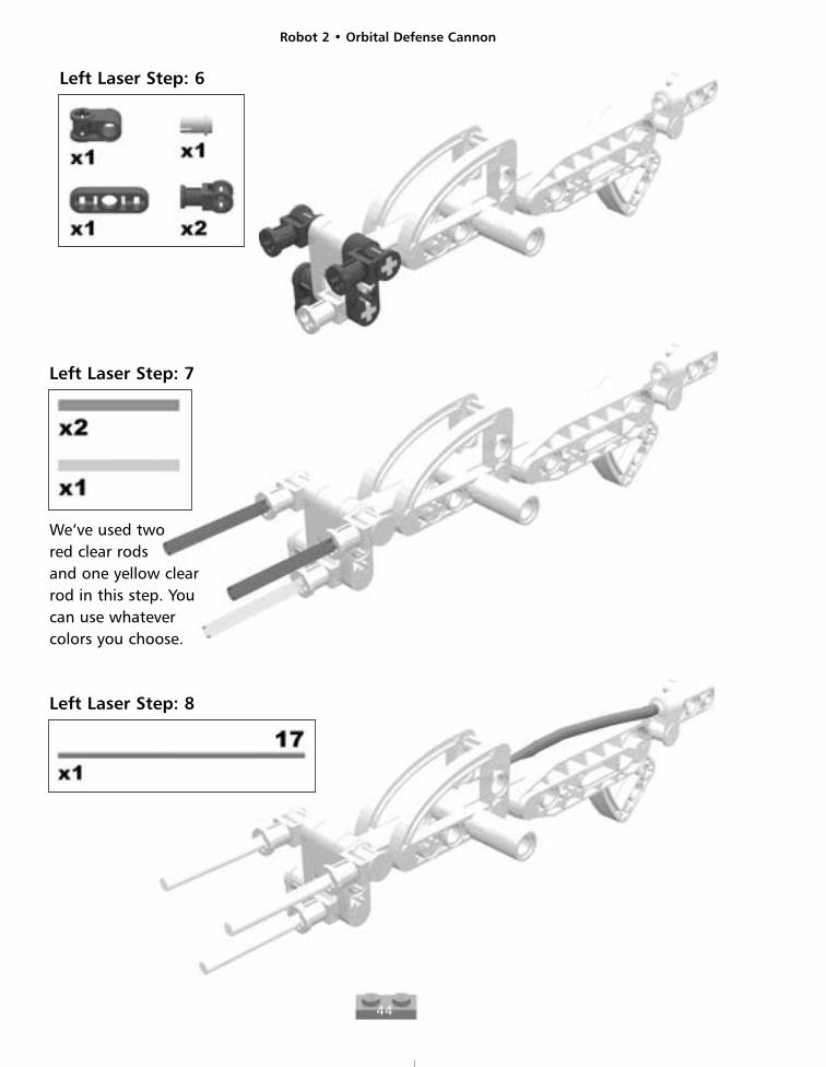
44
Left Laser Step: 7
We’ve used twored clear rods and one yellow clearrod in this step. Youcan use whatever colors you choose.
Left Laser Step: 8
Left Laser Step: 6
Robot 2 • Orbital Defense Cannon
45
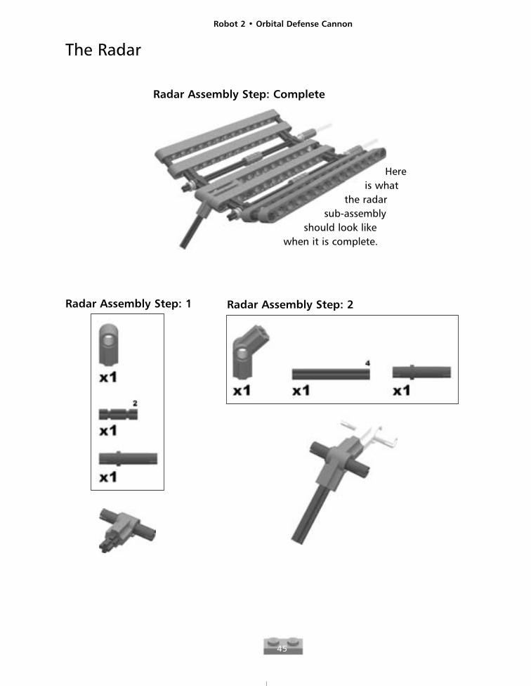
Radar Assembly Step: Complete
The Radar
Hereis what
the radarsub-assembly
should look like when it is complete.
Radar Assembly Step: 1 Radar Assembly Step: 2
Robot 2 • Orbital Defense Cannon
46
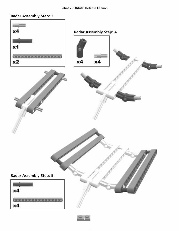
Radar Assembly Step: 3
Radar Assembly Step: 4
Radar Assembly Step: 5
Robot 2 • Orbital Defense Cannon
47
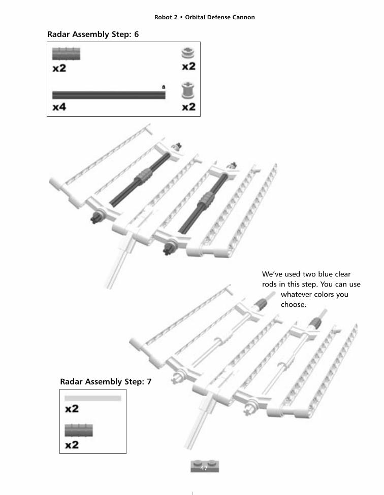
Radar Assembly Step: 6
Radar Assembly Step: 7
We’ve used two blue clearrods in this step. You can use
whatever colors youchoose.
Robot 2 • Orbital Defense Cannon
48
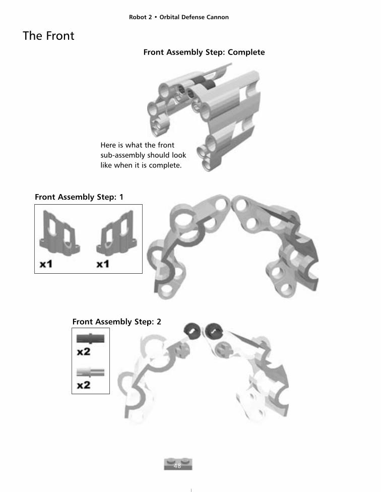
The FrontFront Assembly Step: Complete
Here is what the frontsub-assembly should looklike when it is complete.
Front Assembly Step: 1
Front Assembly Step: 2
Robot 2 • Orbital Defense Cannon
49
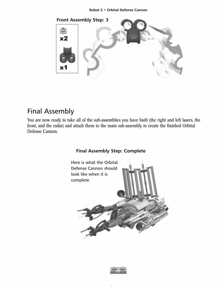
Front Assembly Step: 3
Final AssemblyYou are now ready to take all of the sub-assemblies you have built (the right and left lasers, thefront, and the radar) and attach them to the main sub-assembly to create the finished OrbitalDefense Cannon.
Final Assembly Step: Complete
Here is what the OrbitalDefense Cannon shouldlook like when it iscomplete.
Robot 2 • Orbital Defense Cannon
50
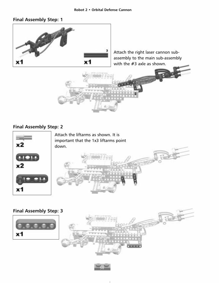
Final Assembly Step: 1
Attach the right laser cannon sub-assembly to the main sub-assemblywith the #3 axle as shown.
Final Assembly Step: 2
Attach the liftarms as shown. It isimportant that the 1x3 liftarms pointdown.
Final Assembly Step: 3
Robot 2 • Orbital Defense Cannon
51
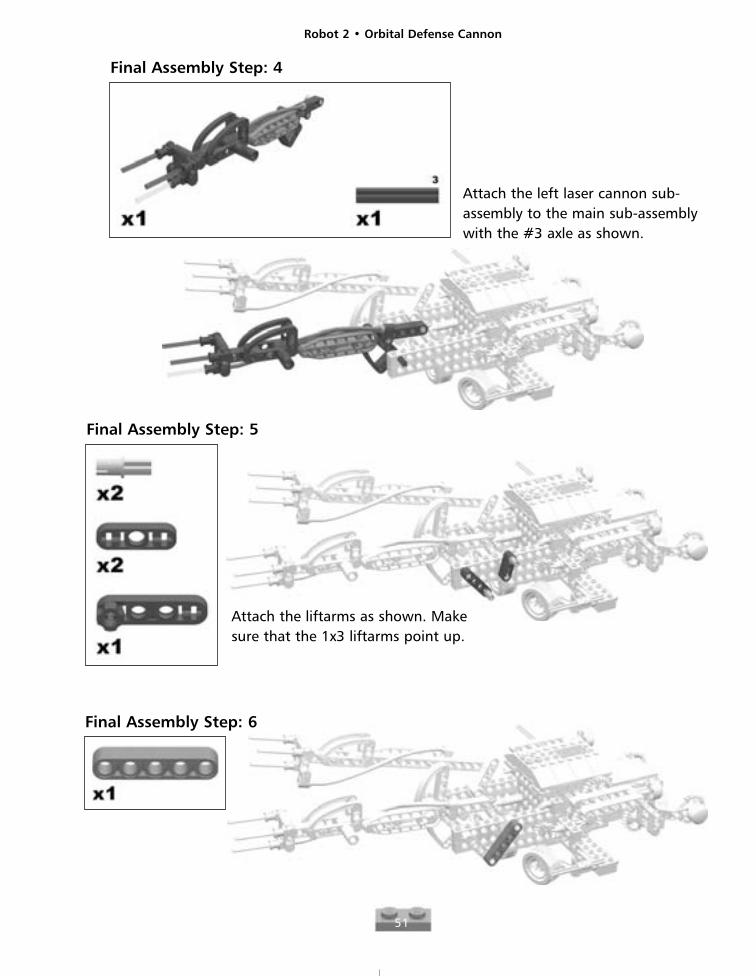
Final Assembly Step: 4
Attach the left laser cannon sub-assembly to the main sub-assemblywith the #3 axle as shown.
Final Assembly Step: 5
Final Assembly Step: 6
Attach the liftarms as shown. Makesure that the 1x3 liftarms point up.
Robot 2 • Orbital Defense Cannon
52
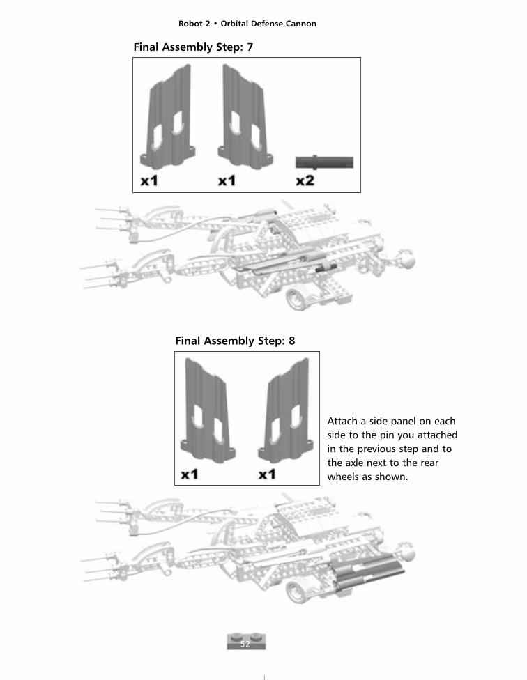
Final Assembly Step: 7
Final Assembly Step: 8
Attach a side panel on eachside to the pin you attachedin the previous step and tothe axle next to the rearwheels as shown.
Robot 2 • Orbital Defense Cannon
53
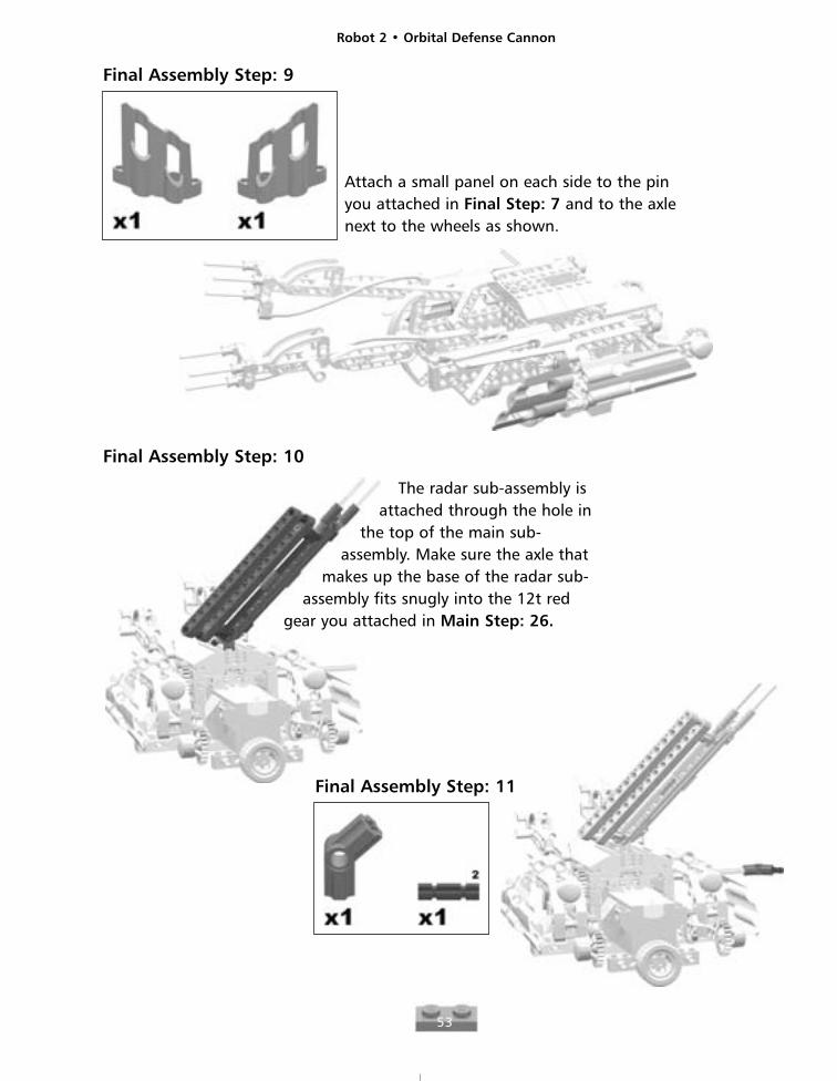
Final Assembly Step: 9
Attach a small panel on each side to the pinyou attached in Final Step: 7 and to the axlenext to the wheels as shown.
Final Assembly Step: 10
The radar sub-assembly isattached through the hole in
the top of the main sub-assembly. Make sure the axle that
makes up the base of the radar sub-assembly fits snugly into the 12t red
gear you attached in Main Step: 26.
Final Assembly Step: 11
Robot 2 • Orbital Defense Cannon
54
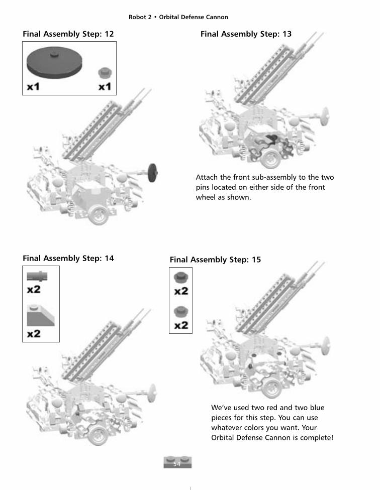
Final Assembly Step: 12
Attach the front sub-assembly to the twopins located on either side of the frontwheel as shown.
Final Assembly Step: 13
Final Assembly Step: 14 Final Assembly Step: 15
We’ve used two red and two bluepieces for this step. You can usewhatever colors you want. YourOrbital Defense Cannon is complete!
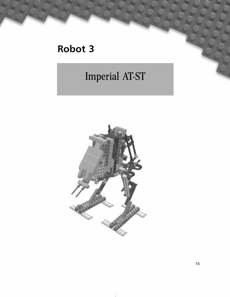
Robot 3
55
Imperial AT-ST
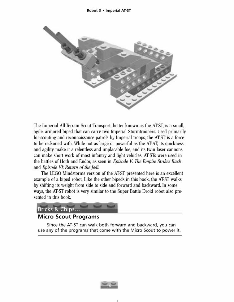
The Imperial All-Terrain Scout Transport, better known as the AT-ST, is a small,agile, armored biped that can carry two Imperial Stormtroopers. Used primarilyfor scouting and reconnaissance patrols by Imperial troops, the AT-ST is a forceto be reckoned with. While not as large or powerful as the AT-AT, its quicknessand agility make it a relentless and implacable foe, and its twin laser cannonscan make short work of most infantry and light vehicles. AT-STs were used inthe battles of Hoth and Endor, as seen in Episode V: The Empire Strikes Backand Episode VI: Return of the Jedi.
The LEGO Mindstorms version of the AT-ST presented here is an excellentexample of a biped robot. Like the other bipeds in this book, the AT-ST walksby shifting its weight from side to side and forward and backward. In someways, the AT-ST robot is very similar to the Super Battle Droid robot also pre-sented in this book.
Bricks & Chips…Micro Scout Programs
Since the AT-ST can walk both forward and backward, you canuse any of the programs that come with the Micro Scout to power it.
Robot 3 • Imperial AT-ST
56
Robot 3 • Imperial AT-ST
57
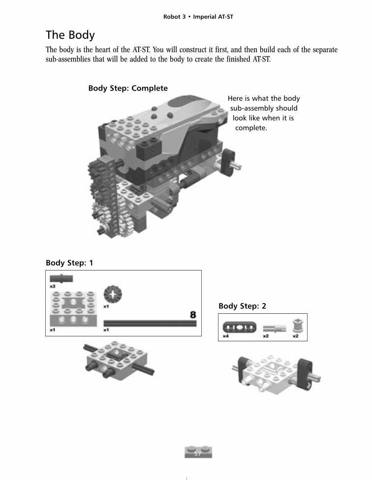
The BodyThe body is the heart of the AT-ST. You will construct it first, and then build each of the separatesub-assemblies that will be added to the body to create the finished AT-ST.
Body Step: CompleteHere is what the bodysub-assembly shouldlook like when it iscomplete.
Body Step: 1
Body Step: 2

Robot 3 • Imperial AT-ST
58
Body Step: 3
Body Step: 4
Make sure thatthe vertical 1x5
liftarm is attached to theaxle through the second hole
from the top, as shown.
Body Step: 5
Robot 3 • Imperial AT-ST
59
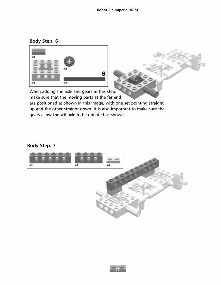
Body Step: 6
When adding the axle and gears in this step, make sure that the moving parts at the far end are positioned as shown in this image, with one set pointing straight up and the other straight down. It is also important to make sure the gears allow the #6 axle to be oriented as shown.
Body Step: 7
Robot 3 • Imperial AT-ST
60
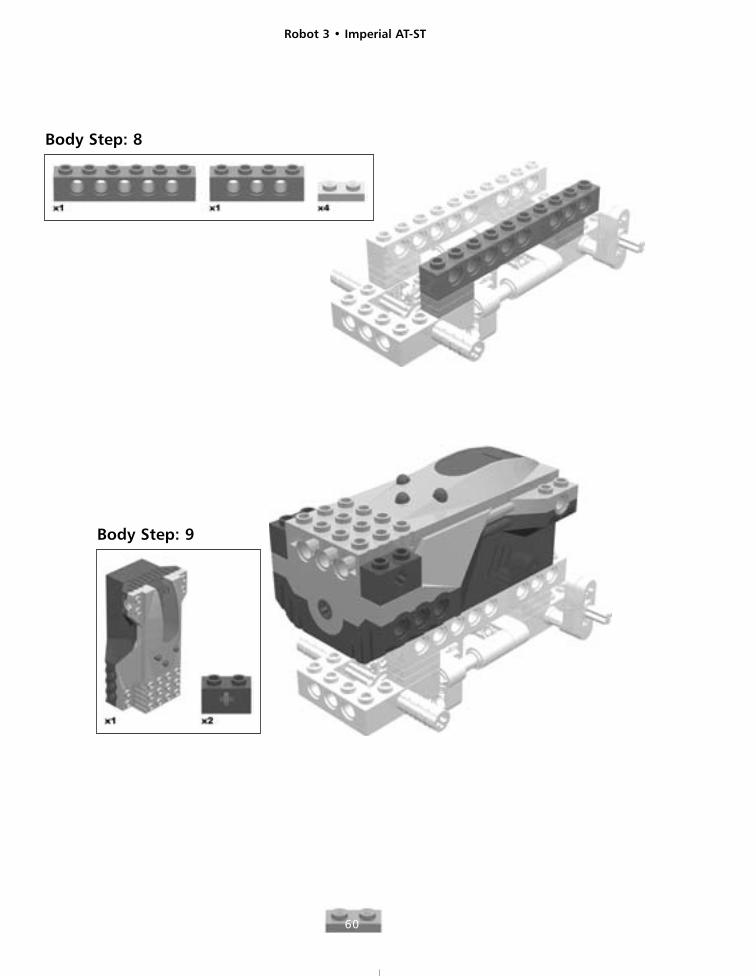
Body Step: 8
Body Step: 9
Robot 3 • Imperial AT-ST
61
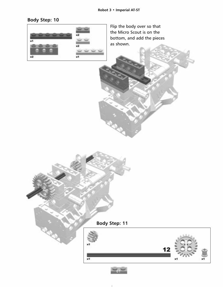
Body Step: 10Flip the body over so thatthe Micro Scout is on thebottom, and add the piecesas shown.
Body Step: 11
Robot 3 • Imperial AT-ST
62
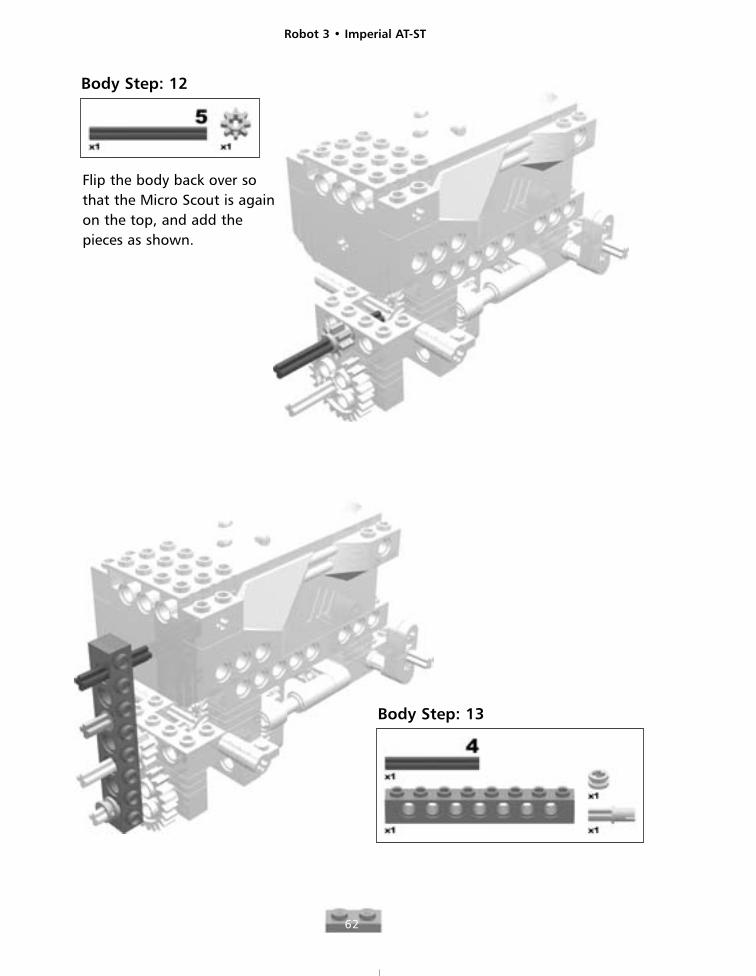
Body Step: 12
Flip the body back over sothat the Micro Scout is againon the top, and add thepieces as shown.
Body Step: 13
Robot 3 • Imperial AT-ST
63
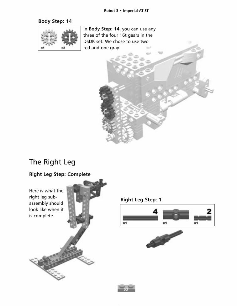
Body Step: 14
In Body Step: 14, you can use anythree of the four 16t gears in the DSDK set. We chose to use two red and one gray.
The Right Leg
Right Leg Step: Complete
Here is what theright leg sub-assembly shouldlook like when itis complete.
Right Leg Step: 1
Robot 3 • Imperial AT-ST
64
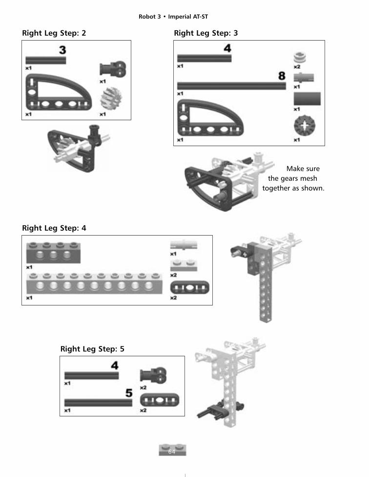
Right Leg Step: 2 Right Leg Step: 3
Make surethe gears mesh
together as shown.
Right Leg Step: 4
Right Leg Step: 5
Robot 3 • Imperial AT-ST
65
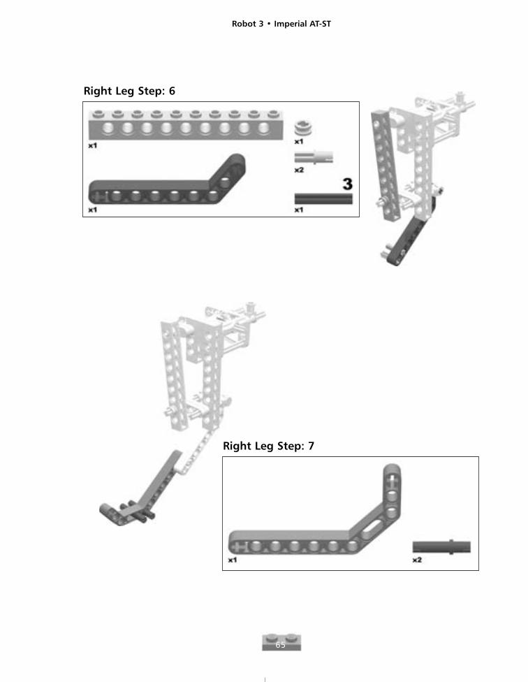
Right Leg Step: 6
Right Leg Step: 7
Robot 3 • Imperial AT-ST
66
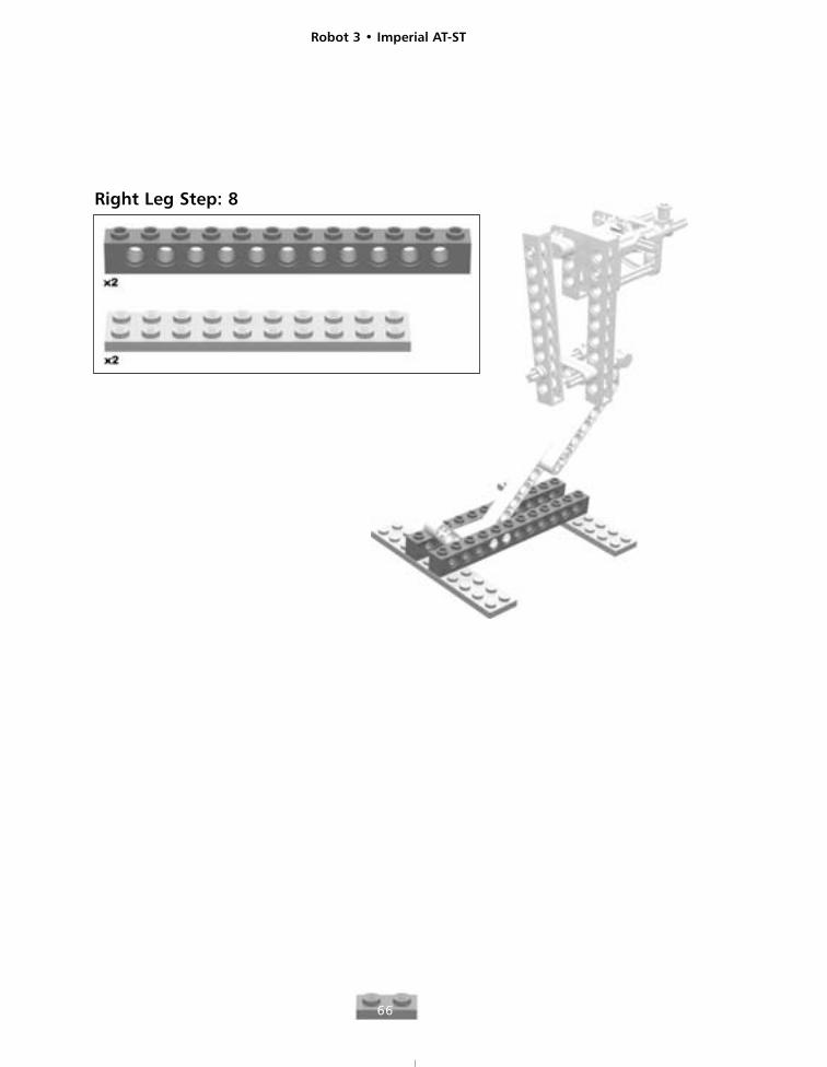
Right Leg Step: 8
Robot 3 • Imperial AT-ST
67
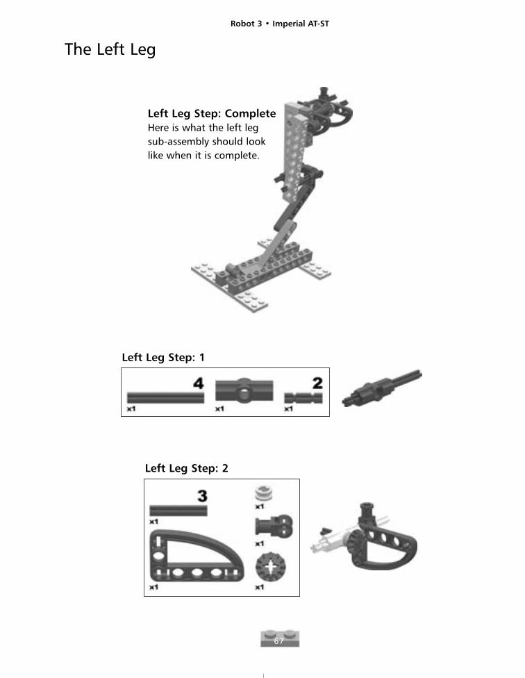
The Left Leg
Left Leg Step: CompleteHere is what the left legsub-assembly should looklike when it is complete.
Left Leg Step: 1
Left Leg Step: 2
Robot 3 • Imperial AT-ST
68
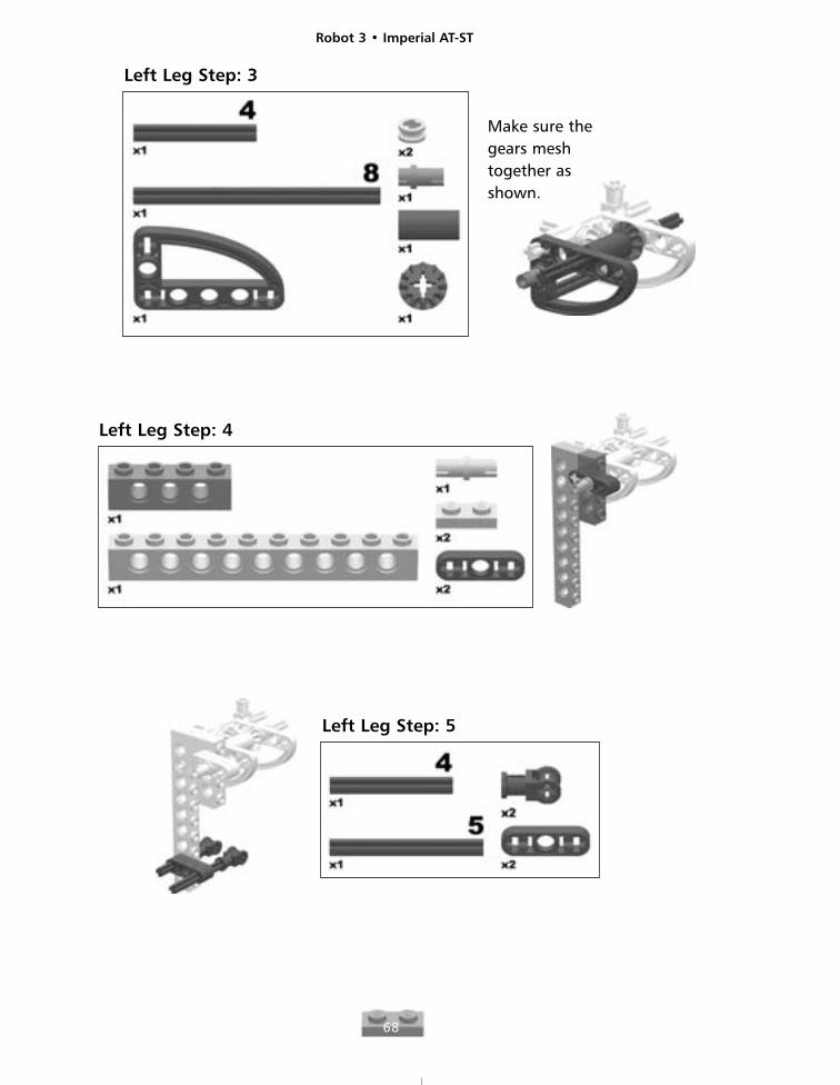
Left Leg Step: 3
Make sure thegears meshtogether asshown.
Left Leg Step: 4
Left Leg Step: 5
Robot 3 • Imperial AT-ST
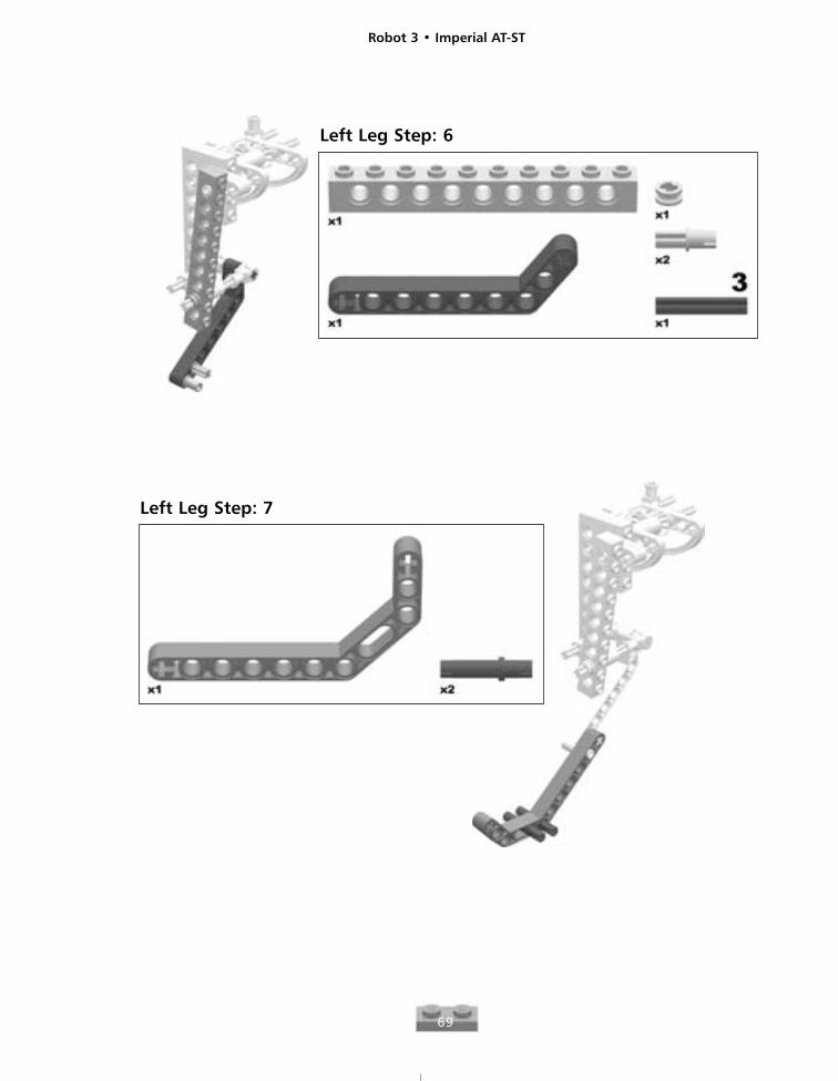
69
Left Leg Step: 7
Left Leg Step: 6
Robot 3 • Imperial AT-ST
70
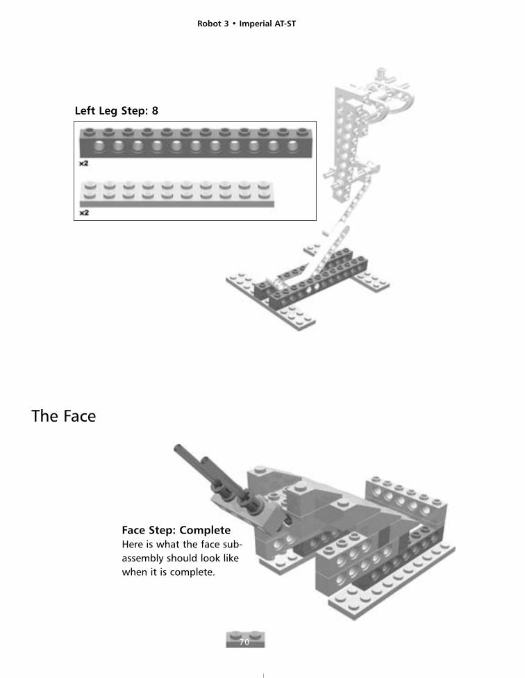
Left Leg Step: 8
Face Step: CompleteHere is what the face sub-assembly should look likewhen it is complete.
The Face
Robot 3 • Imperial AT-ST
71
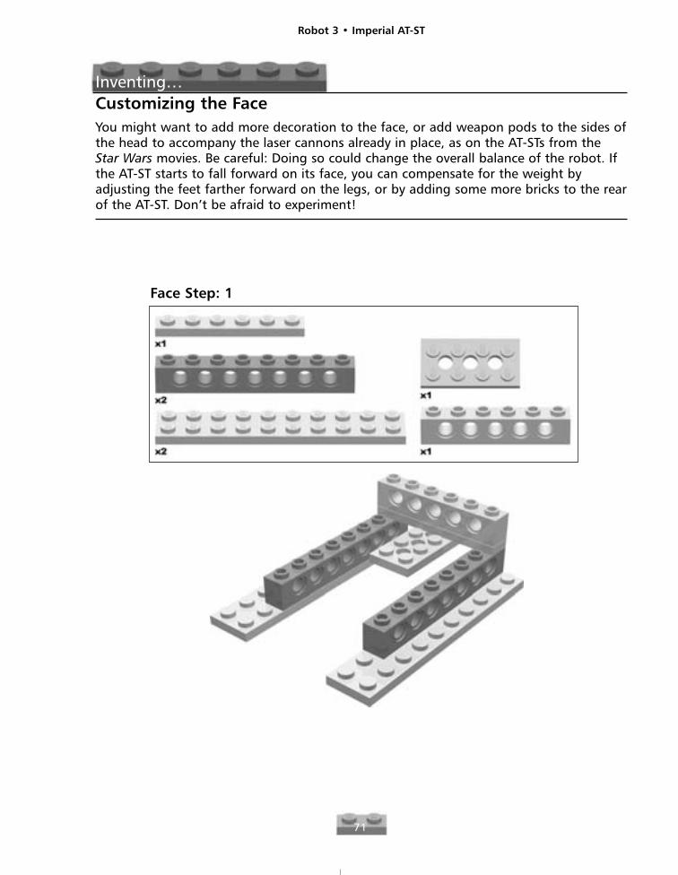
Inventing…Customizing the FaceYou might want to add more decoration to the face, or add weapon pods to the sides ofthe head to accompany the laser cannons already in place, as on the AT-STs from theStar Wars movies. Be careful: Doing so could change the overall balance of the robot. Ifthe AT-ST starts to fall forward on its face, you can compensate for the weight byadjusting the feet farther forward on the legs, or by adding some more bricks to the rearof the AT-ST. Don’t be afraid to experiment!
Face Step: 1
Robot 3 • Imperial AT-ST
72
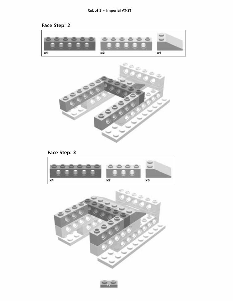
Face Step: 2
Face Step: 3
Robot 3 • Imperial AT-ST
73
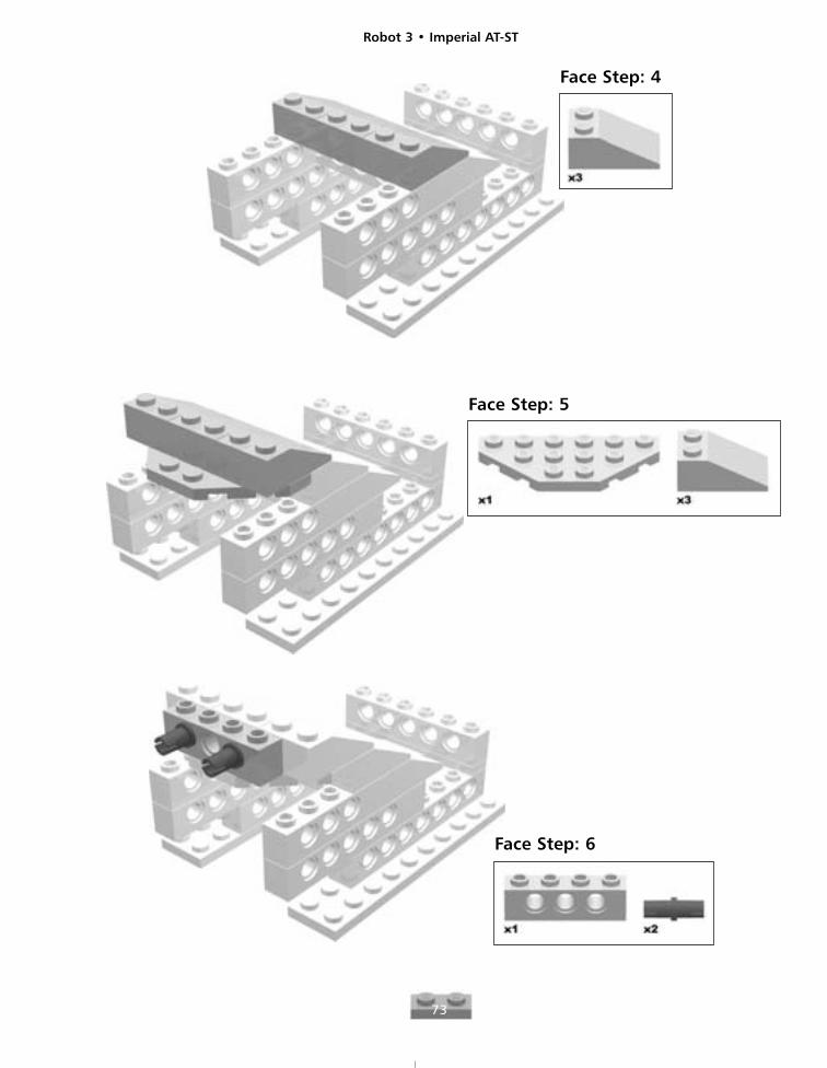
Face Step: 5
Face Step: 4
Face Step: 6
Robot 3 • Imperial AT-ST
74
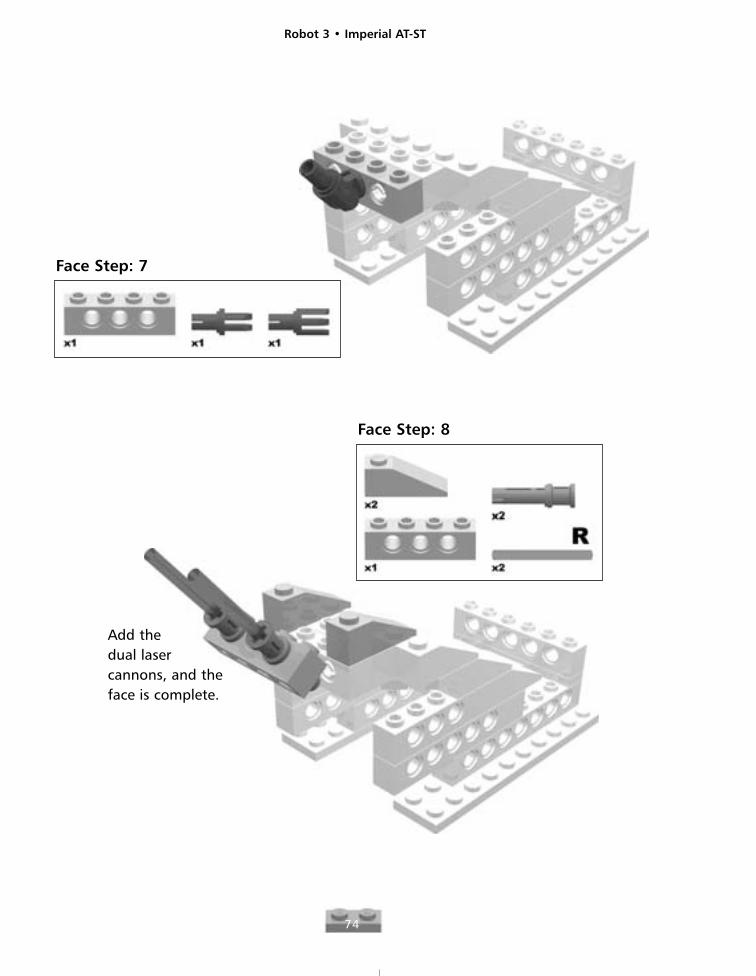
Face Step: 7
Face Step: 8
Add thedual lasercannons, and theface is complete.
Robot 3 • Imperial AT-ST
75
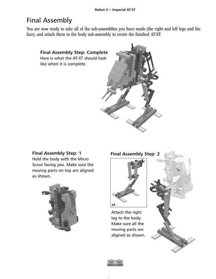
Final AssemblyYou are now ready to take all of the sub-assemblies you have made (the right and left legs and theface), and attach them to the body sub-assembly to create the finished AT-ST.
Final Assembly Step: CompleteHere is what the AT-ST should looklike when it is complete.
Final Assembly Step: 1Hold the body with the MicroScout facing you. Make sure themoving parts on top are alignedas shown.
Final Assembly Step: 2
Attach the rightleg to the body.Make sure all themoving parts arealigned as shown.
Robot 3 • Imperial AT-ST
76
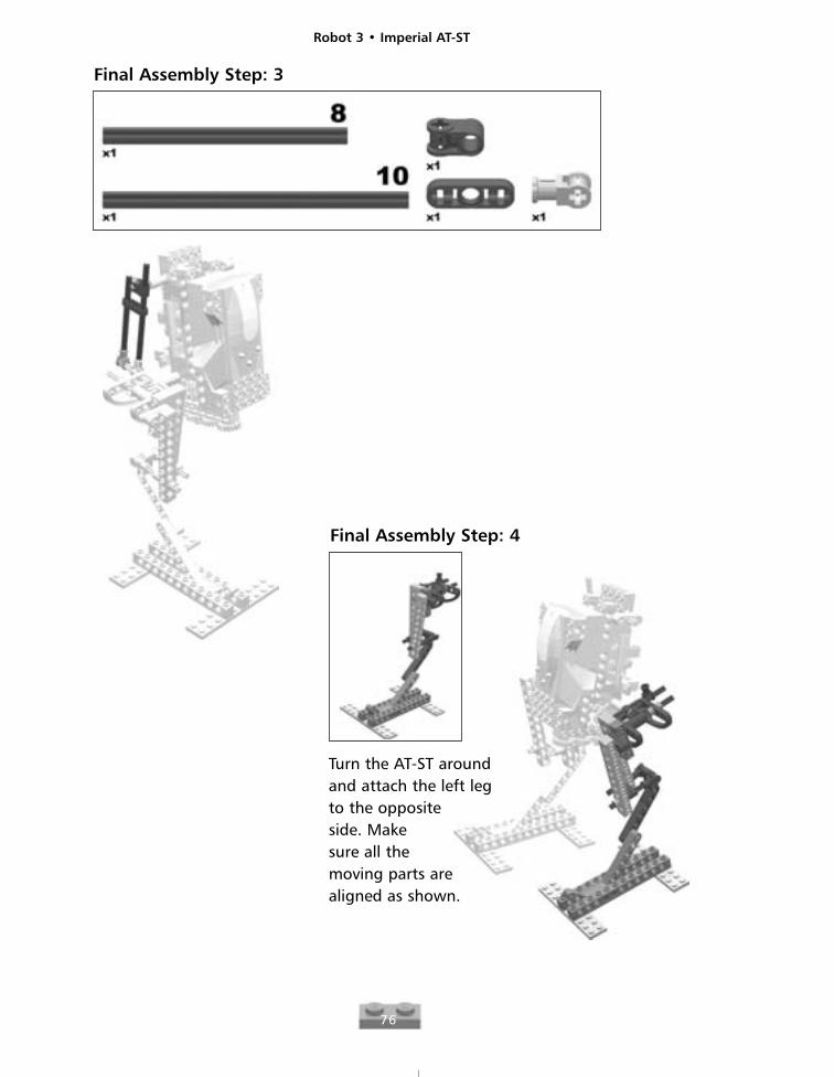
Final Assembly Step: 3
Final Assembly Step: 4
Turn the AT-ST aroundand attach the left legto the oppositeside. Makesure all themoving parts arealigned as shown.
Robot 3 • Imperial AT-ST
77
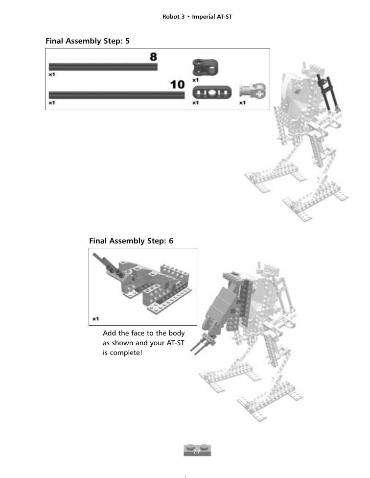
Final Assembly Step: 5
Final Assembly Step: 6
Add the face to the bodyas shown and your AT-STis complete!

Robot 4
79
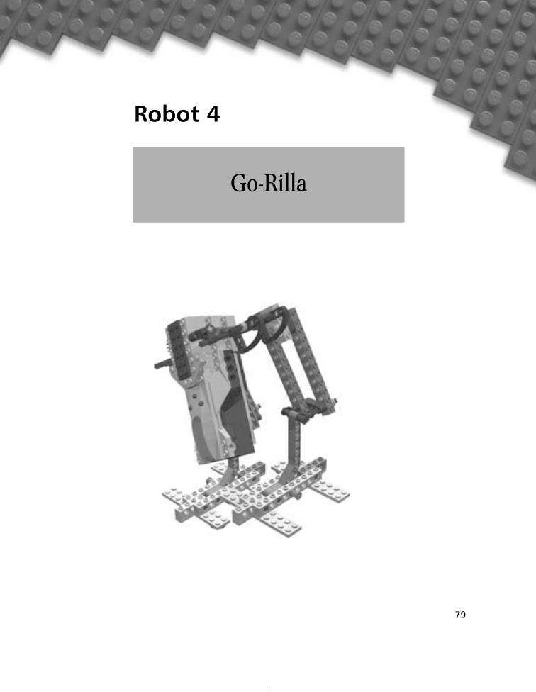
Go-Rilla
Robot 4 • Go-Rilla
80
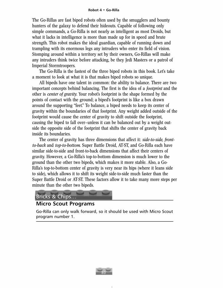
The Go-Rillas are fast biped robots often used by the smugglers and bountyhunters of the galaxy to defend their hideouts. Capable of following onlysimple commands, a Go-Rilla is not nearly as intelligent as most Droids, butwhat it lacks in intelligence is more than made up for in speed and brutestrength. This robot makes the ideal guardian, capable of running down andtrampling with its enormous legs any intruders who enter its field of vision.Stomping around within a territory set by their owners, Go-Rillas will makeany intruders think twice before attacking, be they Jedi Masters or a patrol ofImperial Stormtroopers.
The Go-Rilla is the fastest of the three biped robots in this book. Let’s takea moment to look at what it is that makes biped robots so unique.
All bipeds have one talent in common: the ability to balance. There are twoimportant concepts behind balancing. The first is the idea of a footprint and theother is center of gravity. Your robot’s footprint is the shape formed by thepoints of contact with the ground; a biped’s footprint is like a box drawnaround the supporting “feet.” To balance, a biped needs to keep its center ofgravity within the boundaries of that footprint. Any weight added outside of thefootprint would cause the center of gravity to shift outside the footprint,causing the biped to fall over—unless it can be balanced out by a weight out-side the opposite side of the footprint that shifts the center of gravity backinside its boundaries.
The center of gravity has three dimensions that affect it: side-to-side, front-to-back and top-to-bottom. Super Battle Droid, AT-ST, and Go-Rilla each havesimilar side-to-side and front-to-back dimensions that affect their centers ofgravity. However, a Go-Rilla’s top-to-bottom dimension is much lower to theground than the other two bipeds, which makes it more stable. Also, a Go-Rilla’s top-to-bottom center of gravity is very near its hips (where it leans sideto side), which allows it to shift its weight side-to-side much faster than theSuper Battle Droid or AT-ST. These factors allow it to take many more steps perminute than the other two bipeds.
Bricks & Chips…Micro Scout ProgramsGo-Rilla can only walk forward, so it should be used with Micro Scoutprogram number 1.
Robot 4 • Go-Rilla
81
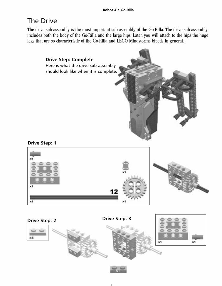
The DriveThe drive sub-assembly is the most important sub-assembly of the Go-Rilla. The drive sub-assemblyincludes both the body of the Go-Rilla and the large hips. Later, you will attach to the hips the hugelegs that are so characteristic of the Go-Rilla and LEGO Mindstorms bipeds in general.
Drive Step: CompleteHere is what the drive sub-assemblyshould look like when it is complete.
Drive Step: 1
Drive Step: 3Drive Step: 2
Robot 4 • Go-Rilla
82
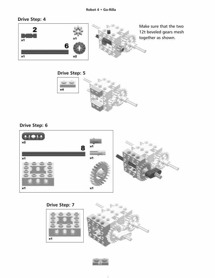
Drive Step: 4
Drive Step: 5
Drive Step: 6
Make sure that the two12t beveled gears meshtogether as shown.
Drive Step: 7
Robot 4 • Go-Rilla
83
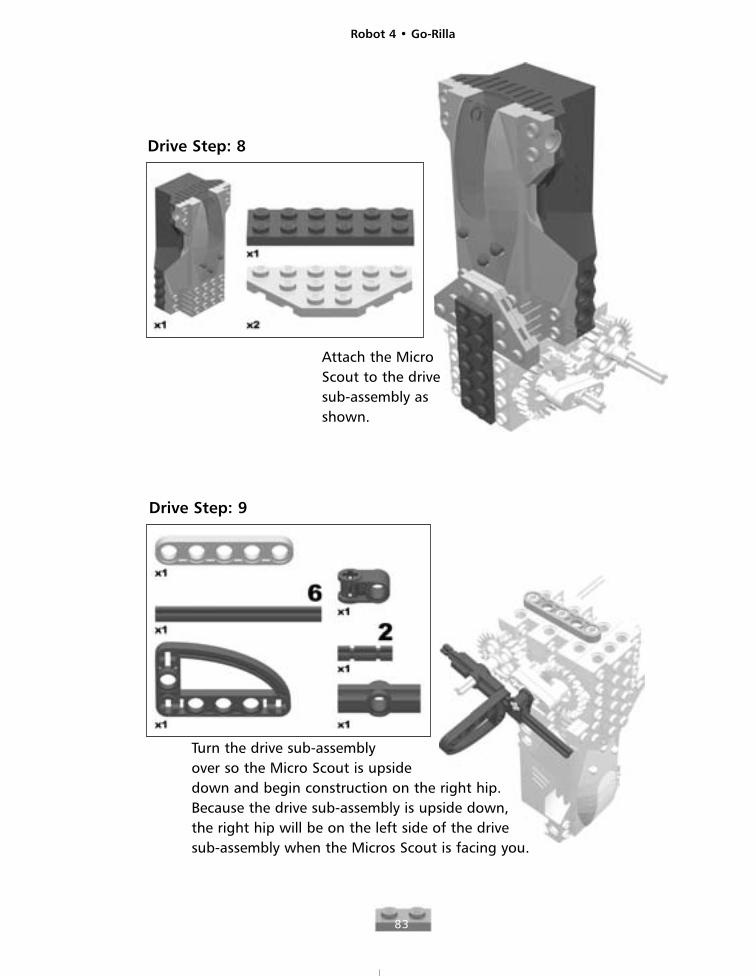
Drive Step: 8
Attach the MicroScout to the drivesub-assembly asshown.
Drive Step: 9
Turn the drive sub-assemblyover so the Micro Scout is upsidedown and begin construction on the right hip.Because the drive sub-assembly is upside down,the right hip will be on the left side of the drivesub-assembly when the Micros Scout is facing you.
Robot 4 • Go-Rilla
84
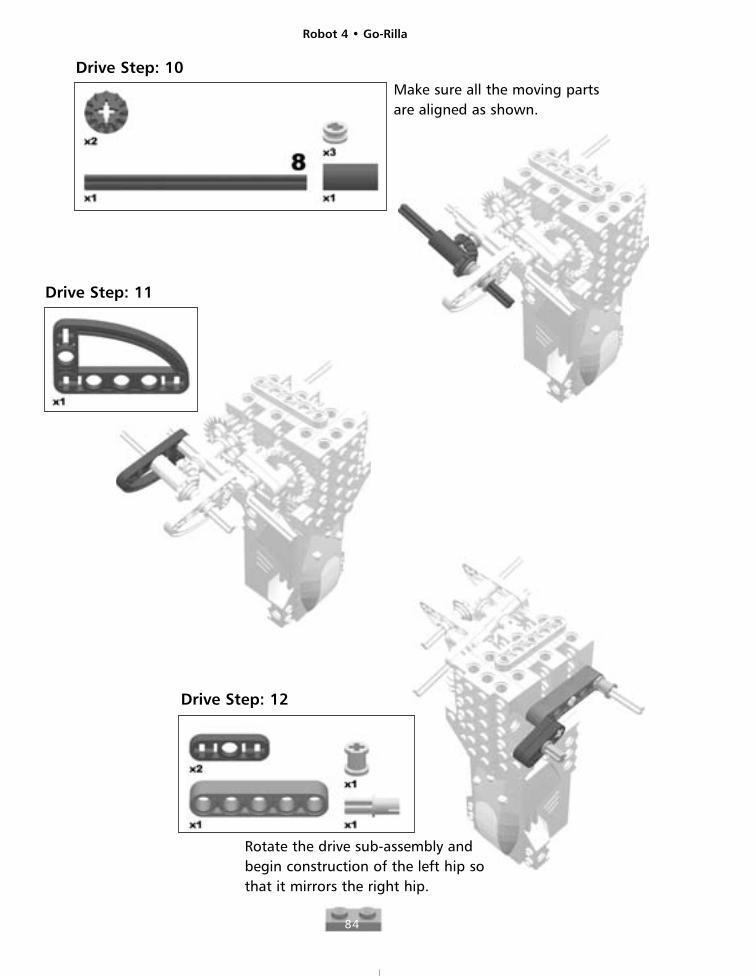
Drive Step: 10Make sure all the moving partsare aligned as shown.
Drive Step: 11
Drive Step: 12
Rotate the drive sub-assembly andbegin construction of the left hip so that it mirrors the right hip.
Robot 4 • Go-Rilla
85
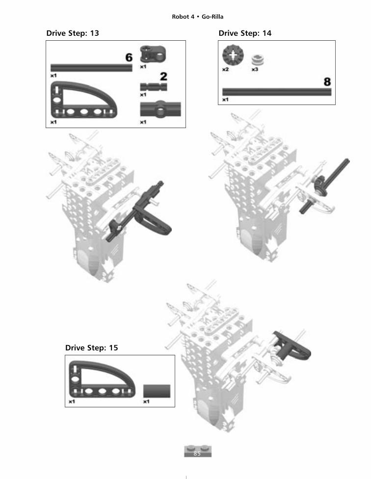
Drive Step: 13 Drive Step: 14
Drive Step: 15
Robot 4 • Go-Rilla
86
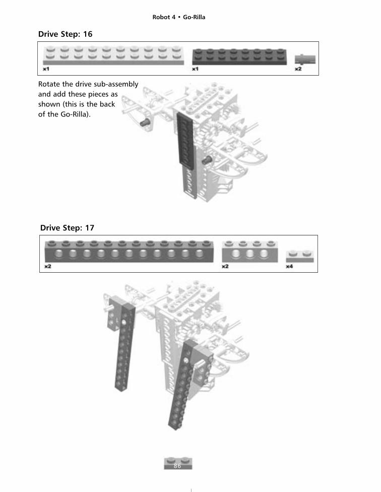
Drive Step: 16
Rotate the drive sub-assembly and add these pieces as shown (this is the back of the Go-Rilla).
Drive Step: 17
Robot 4 • Go-Rilla
87
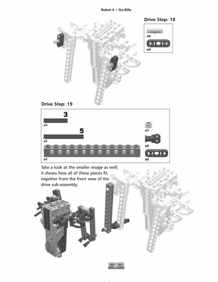
Drive Step: 18
Drive Step: 19
Take a look at the smaller image as well;it shows how all of these pieces fittogether from the front view of thedrive sub-assembly.
Robot 4 • Go-Rilla
88
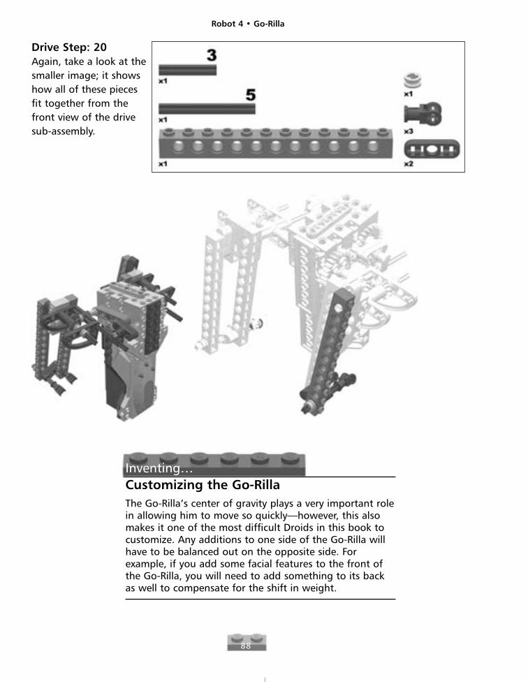
Drive Step: 20Again, take a look at thesmaller image; it showshow all of these piecesfit together from thefront view of the drivesub-assembly.
Inventing…Customizing the Go-RillaThe Go-Rilla’s center of gravity plays a very important rolein allowing him to move so quickly—however, this alsomakes it one of the most difficult Droids in this book tocustomize. Any additions to one side of the Go-Rilla willhave to be balanced out on the opposite side. Forexample, if you add some facial features to the front ofthe Go-Rilla, you will need to add something to its backas well to compensate for the shift in weight.
Robot 4 • Go-Rilla
89
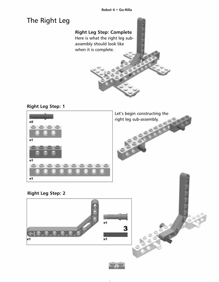
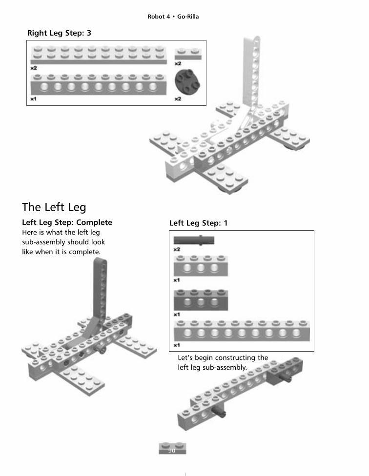
Right Leg Step: CompleteHere is what the right leg sub-assembly should look likewhen it is complete.
Right Leg Step: 1
Right Leg Step: 2
The Right Leg
Let’s begin constructing theright leg sub-assembly.
Robot 4 • Go-Rilla
90
Right Leg Step: 3
The Left LegLeft Leg Step: CompleteHere is what the left legsub-assembly should looklike when it is complete.
Left Leg Step: 1
Let’s begin constructing theleft leg sub-assembly.
Robot 4 • Go-Rilla
91
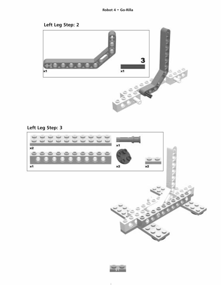
Left Leg Step: 2
Left Leg Step: 3
Robot 4 • Go-Rilla
92
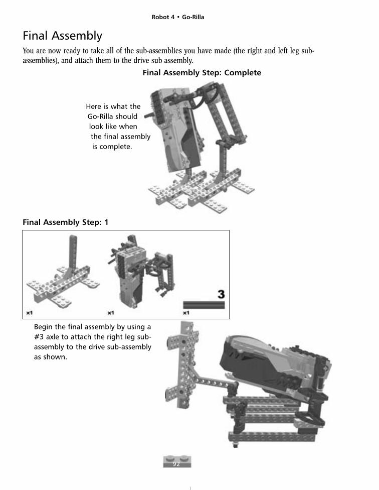
Final AssemblyYou are now ready to take all of the sub-assemblies you have made (the right and left leg sub-assemblies), and attach them to the drive sub-assembly.
Final Assembly Step: Complete
Here is what theGo-Rilla shouldlook like whenthe final assemblyis complete.
Final Assembly Step: 1
Begin the final assembly by using a#3 axle to attach the right leg sub-assembly to the drive sub-assemblyas shown.
Robot 4 • Go-Rilla
93
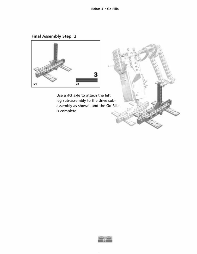
Final Assembly Step: 2
Use a #3 axle to attach the left leg sub-assembly to the drive sub-assembly as shown, and the Go-Rillais complete!

Robot 5
95
X-Stormer
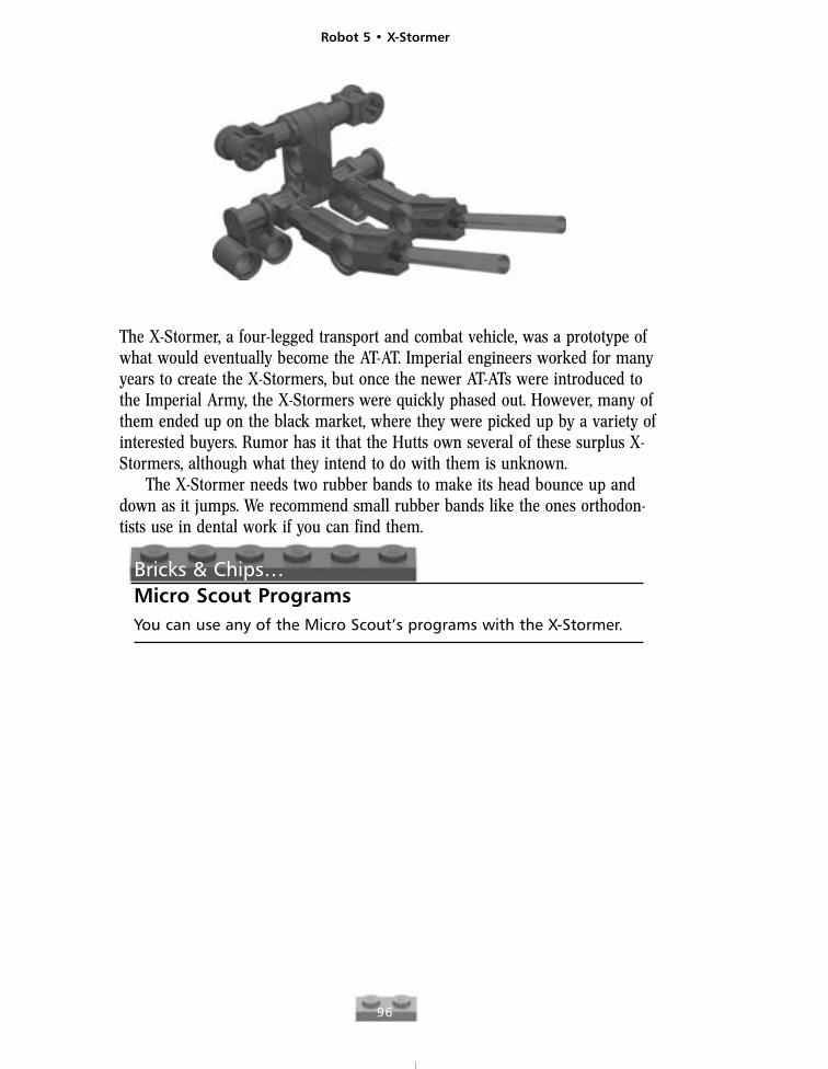
The X-Stormer, a four-legged transport and combat vehicle, was a prototype ofwhat would eventually become the AT-AT. Imperial engineers worked for manyyears to create the X-Stormers, but once the newer AT-ATs were introduced tothe Imperial Army, the X-Stormers were quickly phased out. However, many ofthem ended up on the black market, where they were picked up by a variety ofinterested buyers. Rumor has it that the Hutts own several of these surplus X-Stormers, although what they intend to do with them is unknown.
The X-Stormer needs two rubber bands to make its head bounce up anddown as it jumps. We recommend small rubber bands like the ones orthodon-tists use in dental work if you can find them.
Bricks & Chips…Micro Scout ProgramsYou can use any of the Micro Scout’s programs with the X-Stormer.
Robot 5 • X-Stormer
96
Robot 5 • X-Stormer
97
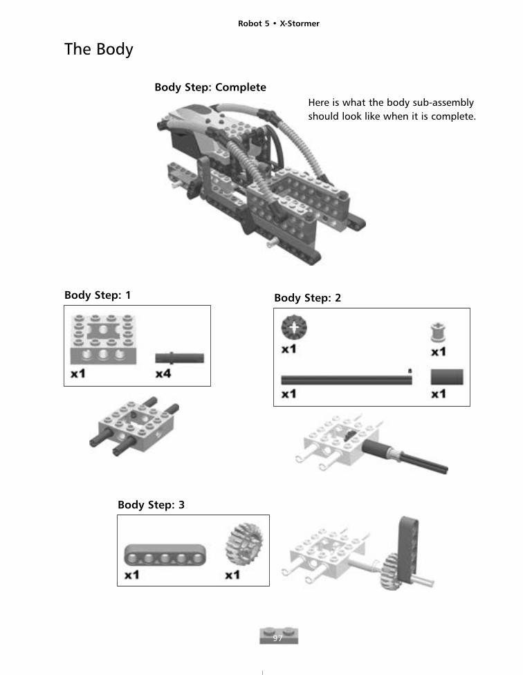
The Body
Body Step: CompleteHere is what the body sub-assemblyshould look like when it is complete.
Body Step: 1 Body Step: 2
Body Step: 3
Robot 5 • X-Stormer
98
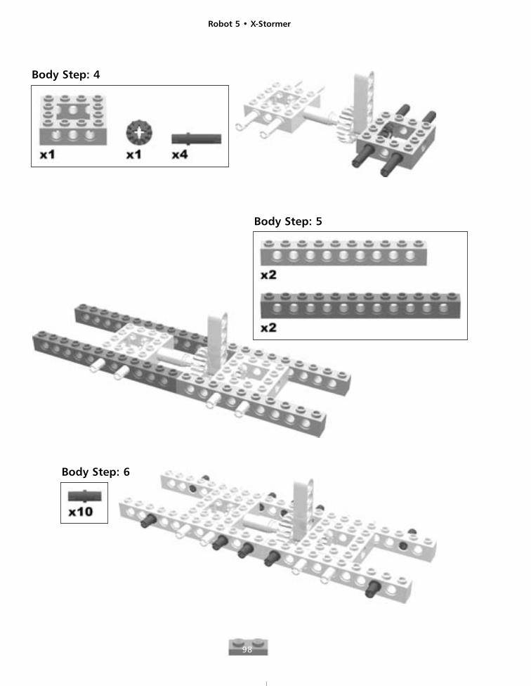
Body Step: 4
Body Step: 5
Body Step: 6
Robot 5 • X-Stormer
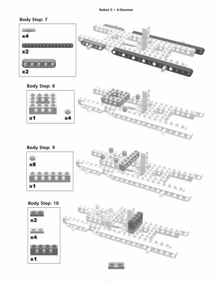
99
Body Step: 7
Body Step: 8
Body Step: 9
Body Step: 10

Robot 5 • X-Stormer
100
Body Step: 11
Body Step: 12
Insert the #5 axle through themiddle hole of th 1x3 brick andthe gears as shown.
Robot 5 • X-Stormer
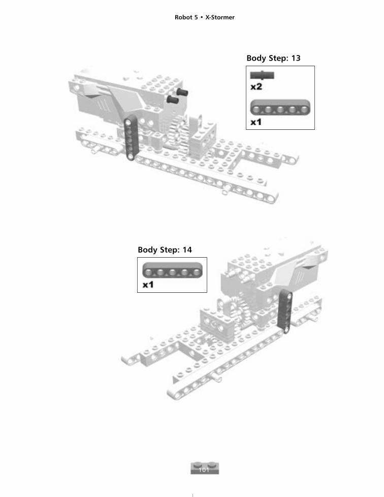
101
Body Step: 13
Body Step: 14
Robot 5 • X-Stormer
102
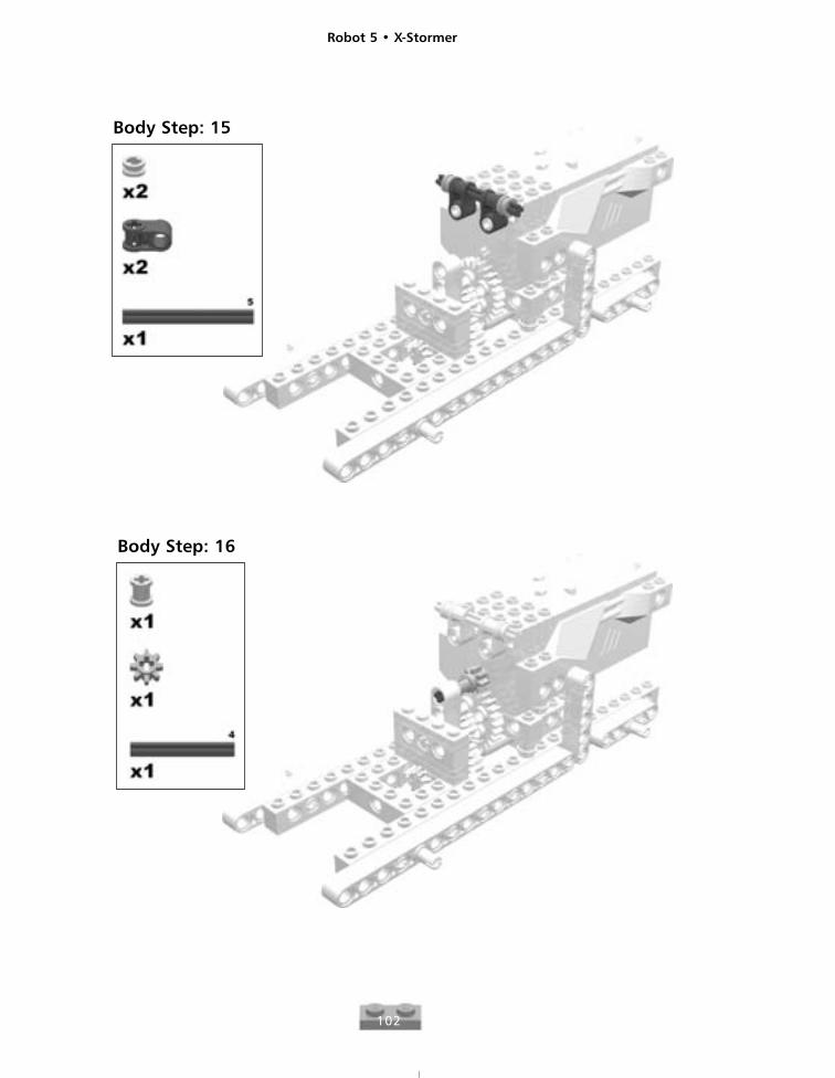
Body Step: 16
Body Step: 15
Robot 5 • X-Stormer
103
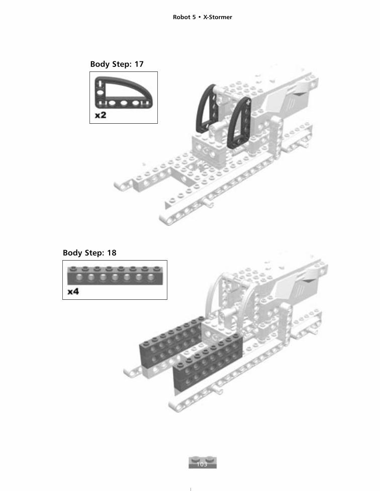
Body Step: 17
Body Step: 18
Robot 5 • X-Stormer
104
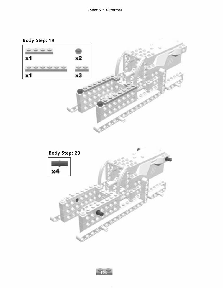
Body Step: 19
Body Step: 20
Robot 5 • X-Stormer
105
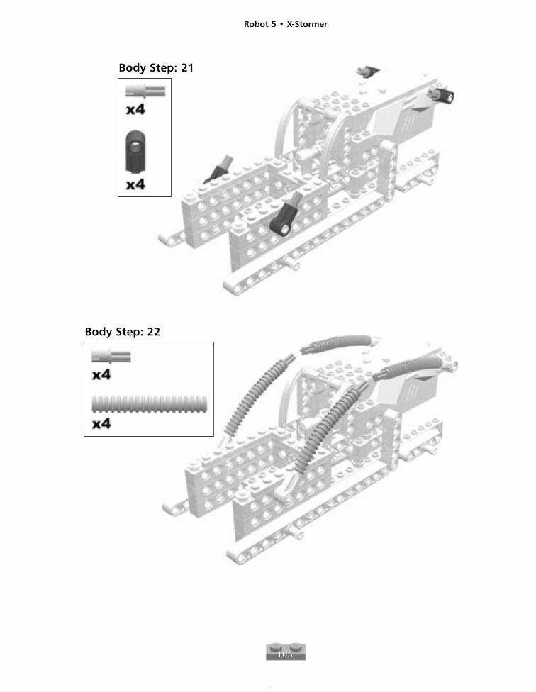
Body Step: 21
Body Step: 22
Robot 5 • X-Stormer
106
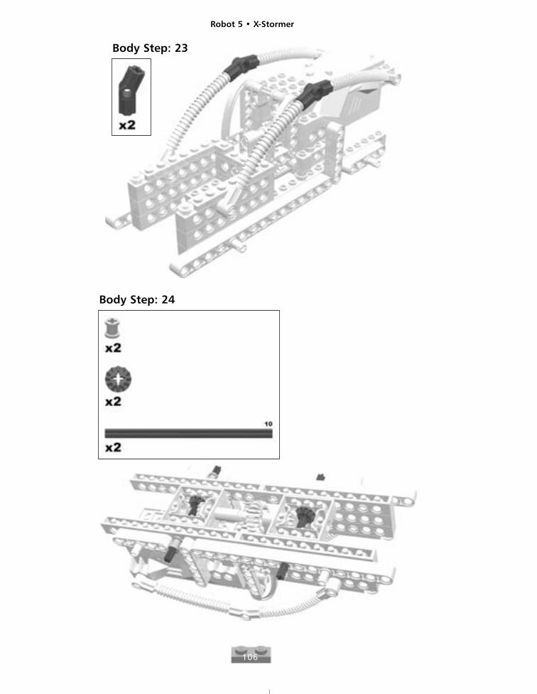
Body Step: 23
Body Step: 24
Robot 5 • X-Stormer
107
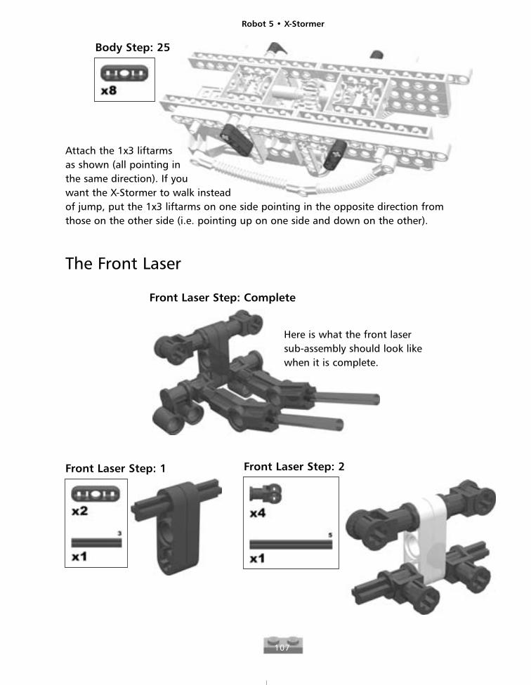
Body Step: 25
Attach the 1x3 liftarms as shown (all pointing in the same direction). If you want the X-Stormer to walk instead of jump, put the 1x3 liftarms on one side pointing in the opposite direction fromthose on the other side (i.e. pointing up on one side and down on the other).
The Front Laser
Front Laser Step: Complete
Here is what the front lasersub-assembly should look likewhen it is complete.
Front Laser Step: 1 Front Laser Step: 2
Robot 5 • X-Stormer
108
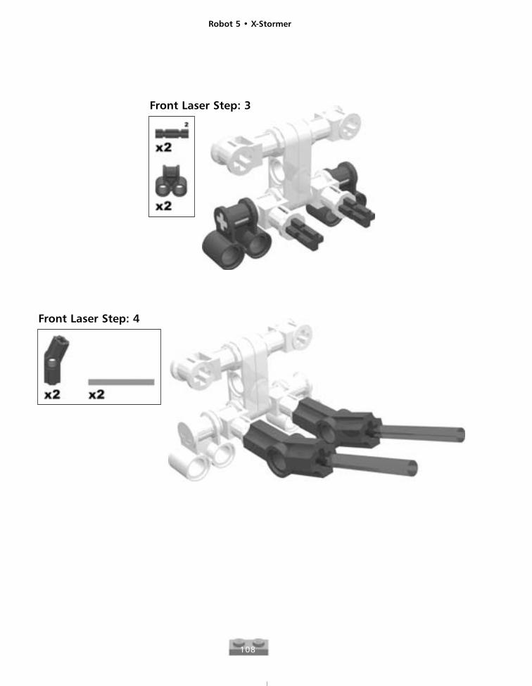
Front Laser Step: 3
Front Laser Step: 4
Robot 5 • X-Stormer
109
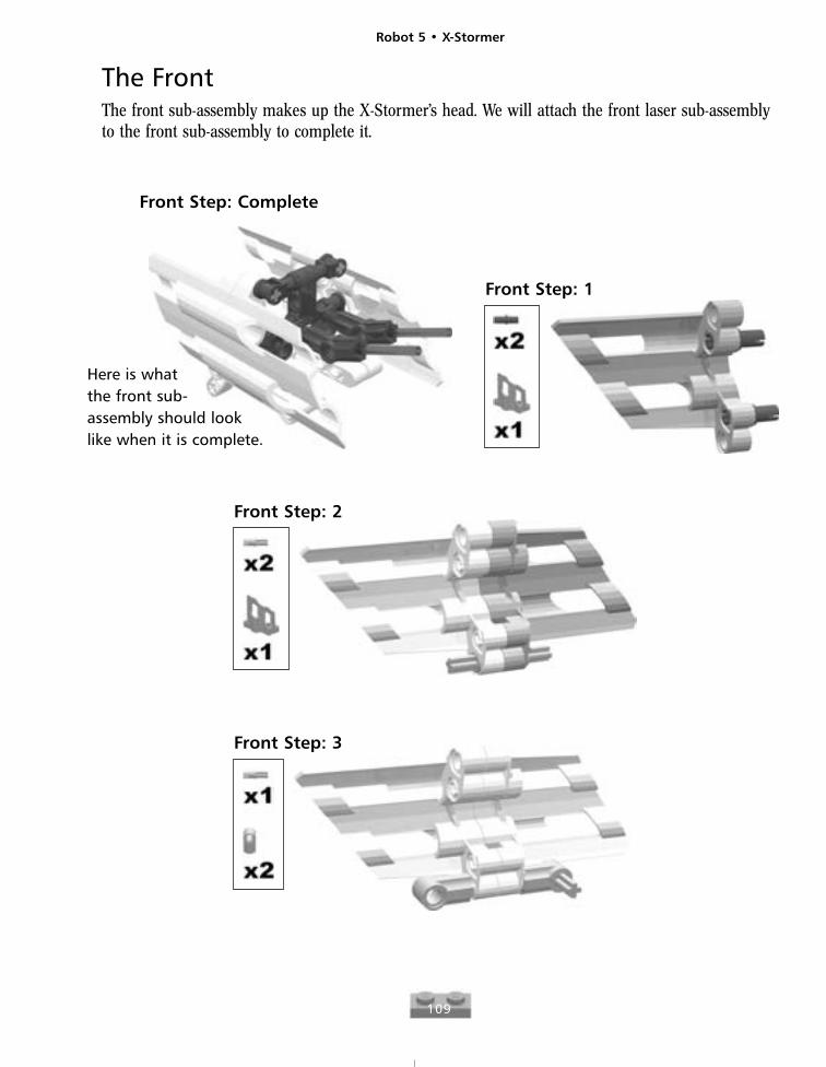
The FrontThe front sub-assembly makes up the X-Stormer’s head. We will attach the front laser sub-assemblyto the front sub-assembly to complete it.
Front Step: Complete
Here is what the front sub-assembly should look like when it is complete.
Front Step: 1
Front Step: 2
Front Step: 3
Robot 5 • X-Stormer
110
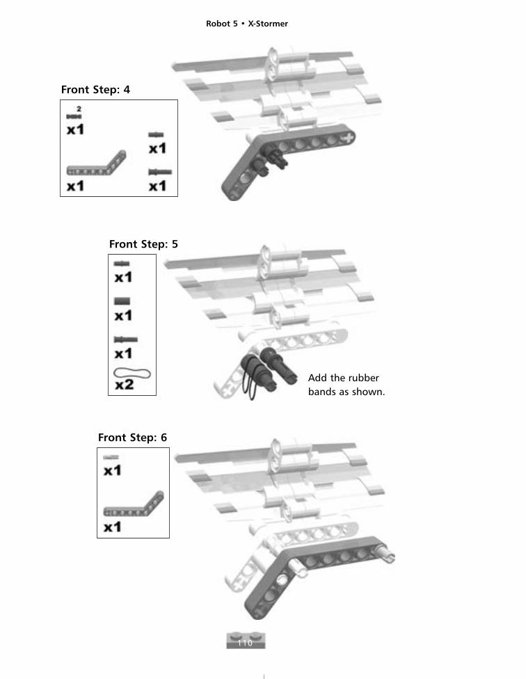
Add the rubberbands as shown.
Front Step: 5
Front Step: 6
Front Step: 4
Robot 5 • X-Stormer
111
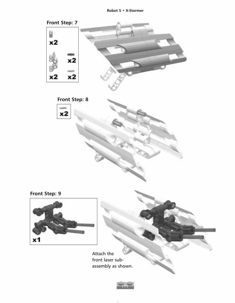
Front Step: 7
Front Step: 8
Front Step: 9
Attach thefront laser sub-assembly as shown.
Robot 5 • X-Stormer
112
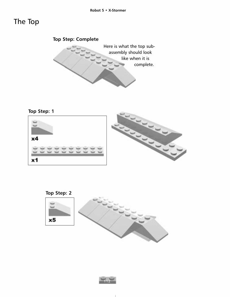
The Top
Top Step: CompleteHere is what the top sub-
assembly should looklike when it is
complete.
Top Step: 1
Top Step: 2
Robot 5 • X-Stormer
113
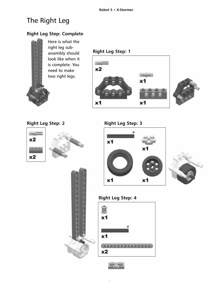
The Right Leg
Right Leg Step: Complete
Here is what theright leg sub-assembly shouldlook like when itis complete. Youneed to maketwo right legs.
Right Leg Step: 1
Right Leg Step: 2 Right Leg Step: 3
Right Leg Step: 4
Robot 5 • X-Stormer
114
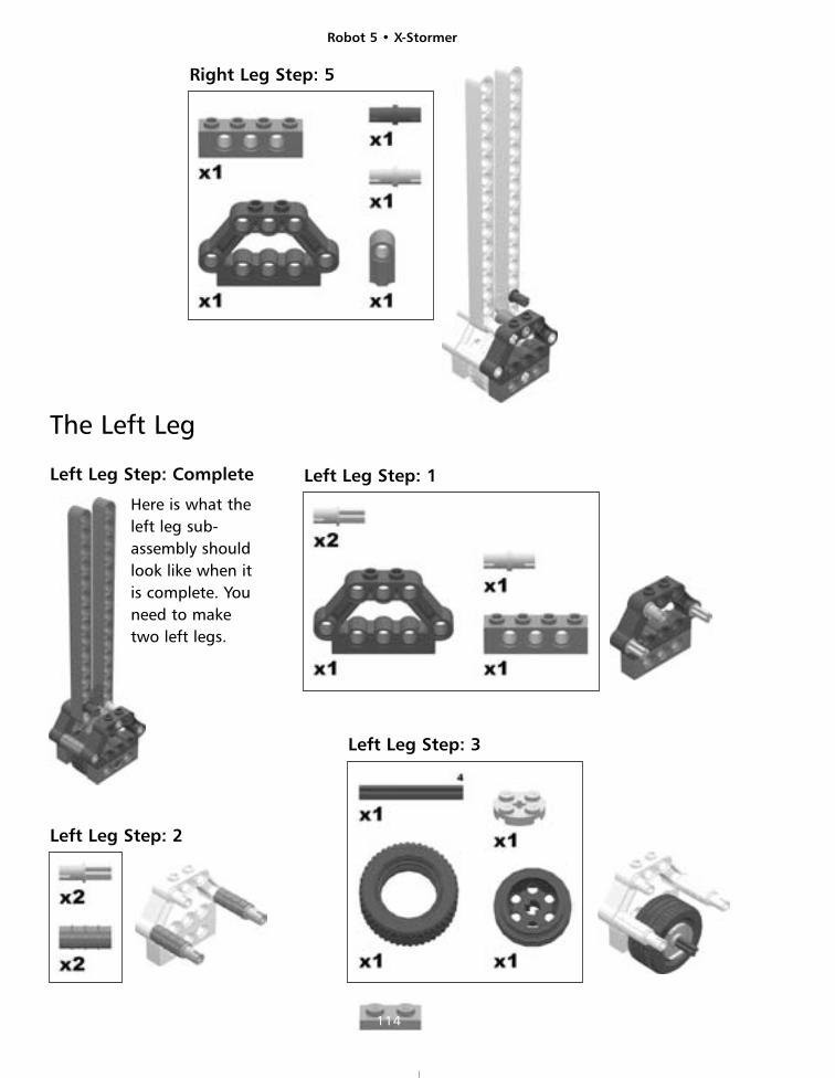
Right Leg Step: 5
The Left Leg
Left Leg Step: Complete
Here is what theleft leg sub-assembly shouldlook like when itis complete. Youneed to maketwo left legs.
Left Leg Step: 1
Left Leg Step: 2
Left Leg Step: 3
Robot 5 • X-Stormer
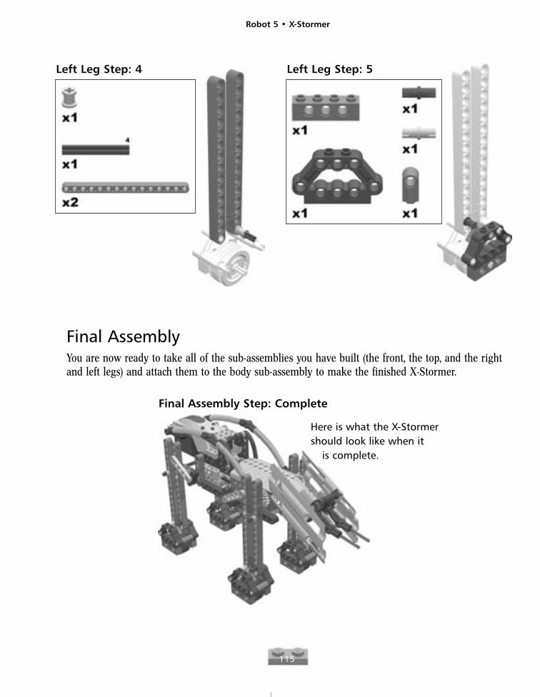
115
Left Leg Step: 4 Left Leg Step: 5
Final AssemblyYou are now ready to take all of the sub-assemblies you have built (the front, the top, and the rightand left legs) and attach them to the body sub-assembly to make the finished X-Stormer.
Final Assembly Step: Complete
Here is what the X-Stormershould look like when it
is complete.
Robot 5 • X-Stormer
116
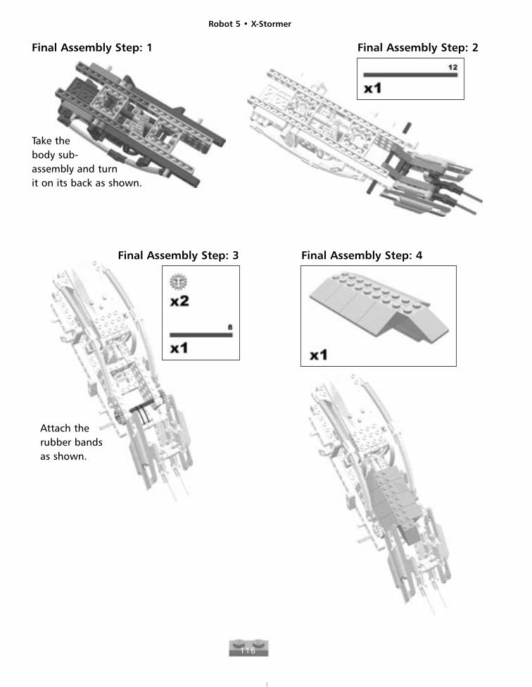
Final Assembly Step: 1
Take thebody sub-assembly and turnit on its back as shown.
Final Assembly Step: 2
Final Assembly Step: 3
Attach therubber bandsas shown.
Final Assembly Step: 4
Robot 5 • X-Stormer
117
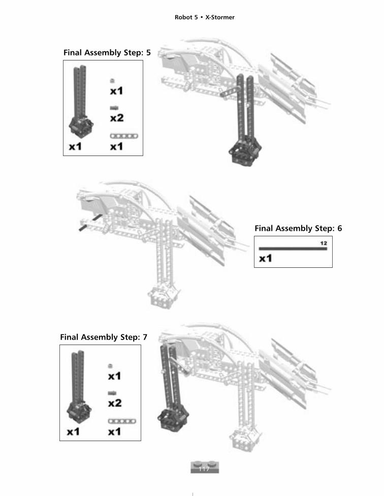
Final Assembly Step: 5
Final Assembly Step: 6
Final Assembly Step: 7
Robot 5 • X-Stormer
118
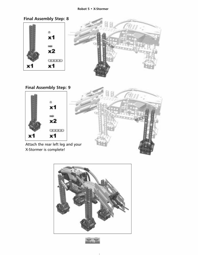
Final Assembly Step: 8
Final Assembly Step: 9
Attach the rear left leg and yourX-Stormer is complete!
Robot 6
119
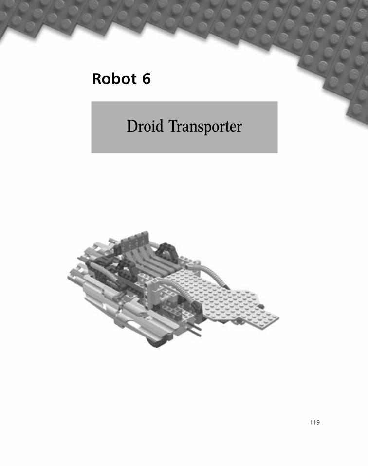
Droid Transporter
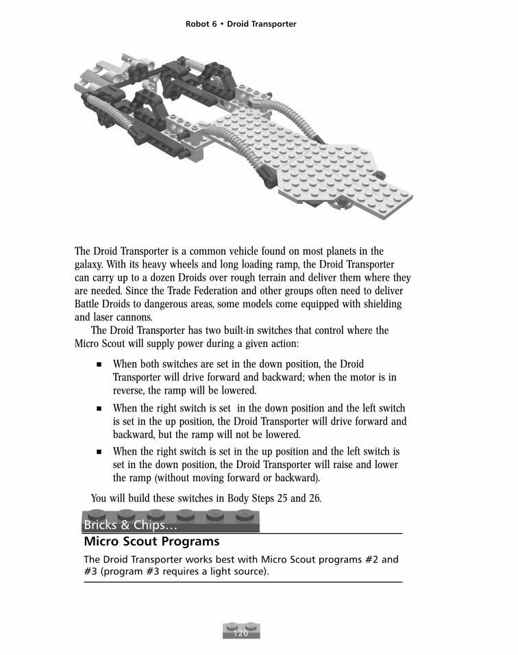
The Droid Transporter is a common vehicle found on most planets in thegalaxy. With its heavy wheels and long loading ramp, the Droid Transportercan carry up to a dozen Droids over rough terrain and deliver them where theyare needed. Since the Trade Federation and other groups often need to deliverBattle Droids to dangerous areas, some models come equipped with shieldingand laser cannons.
The Droid Transporter has two built-in switches that control where theMicro Scout will supply power during a given action:
� When both switches are set in the down position, the DroidTransporter will drive forward and backward; when the motor is inreverse, the ramp will be lowered.
� When the right switch is set in the down position and the left switchis set in the up position, the Droid Transporter will drive forward andbackward, but the ramp will not be lowered.
� When the right switch is set in the up position and the left switch isset in the down position, the Droid Transporter will raise and lowerthe ramp (without moving forward or backward).
You will build these switches in Body Steps 25 and 26.
Bricks & Chips…Micro Scout ProgramsThe Droid Transporter works best with Micro Scout programs #2 and#3 (program #3 requires a light source).
Robot 6 • Droid Transporter
120
Robot 6 • Droid Transporter
121
Body Step: Complete
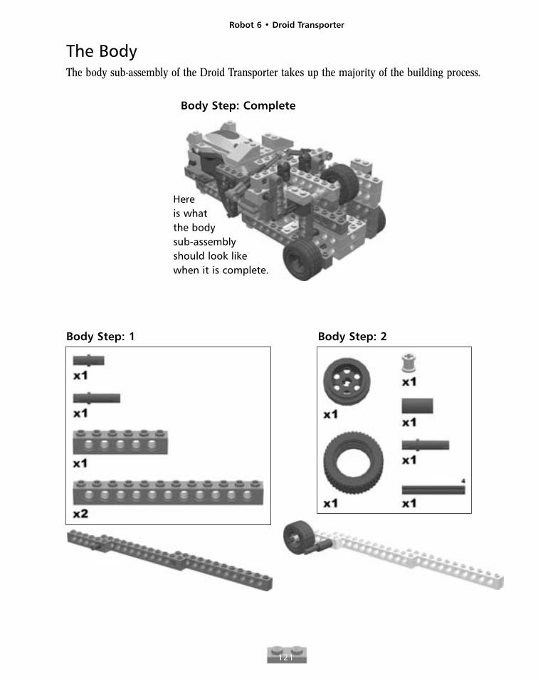
The BodyThe body sub-assembly of the Droid Transporter takes up the majority of the building process.
Hereis whatthe bodysub-assemblyshould look likewhen it is complete.
Body Step: 1 Body Step: 2
Robot 6 • Droid Transporter
122
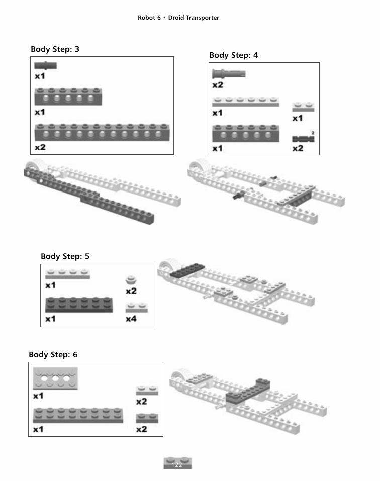
Body Step: 3Body Step: 4
Body Step: 5
Body Step: 6
Robot 6 • Droid Transporter
123
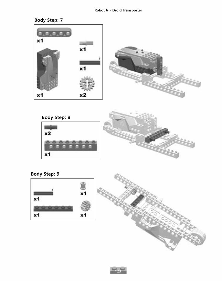
Body Step: 7
Body Step: 8
Body Step: 9
Robot 6 • Droid Transporter
124
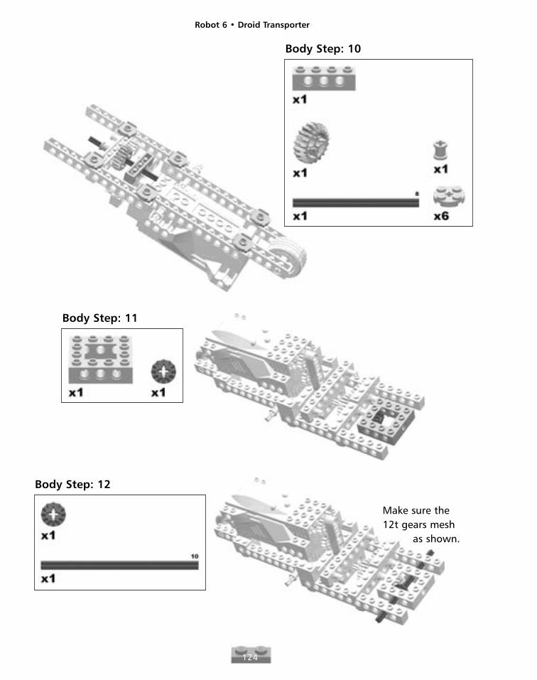
Body Step: 10
Body Step: 11
Body Step: 12
Make sure the 12t gears mesh
as shown.
Robot 6 • Droid Transporter
125
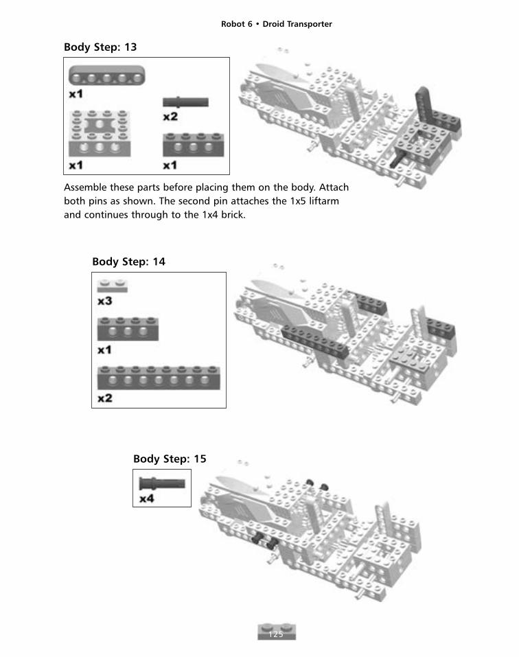
Body Step: 13
Assemble these parts before placing them on the body. Attachboth pins as shown. The second pin attaches the 1x5 liftarmand continues through to the 1x4 brick.
Body Step: 14
Body Step: 15
Robot 6 • Droid Transporter
126
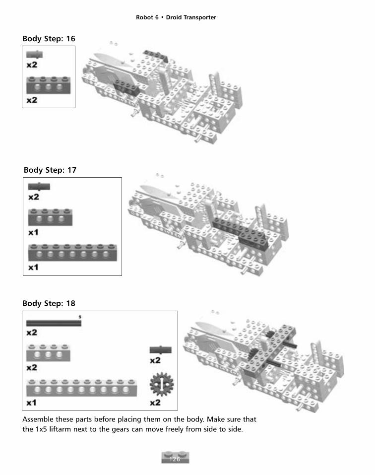
Body Step: 16
Body Step: 17
Body Step: 18
Assemble these parts before placing them on the body. Make sure thatthe 1x5 liftarm next to the gears can move freely from side to side.
Robot 6 • Droid Transporter
127
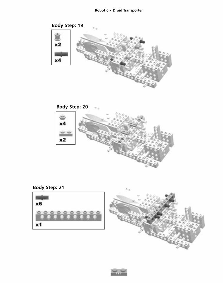
Body Step: 19
Body Step: 20
Body Step: 21
Robot 6 • Droid Transporter
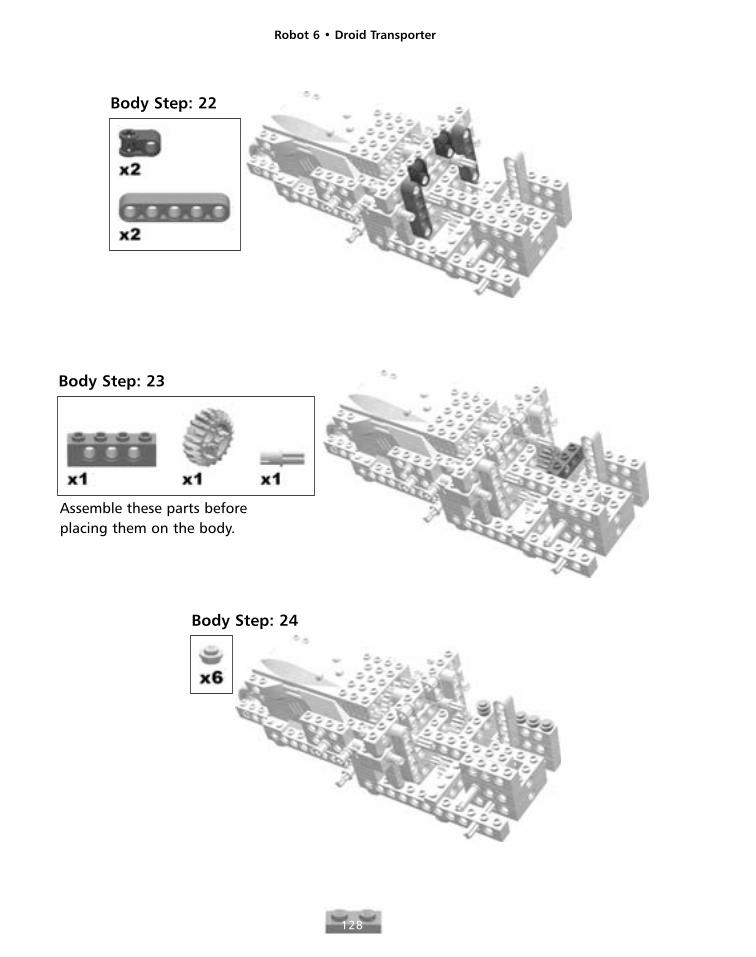
128
Body Step: 22
Body Step: 23
Assemble these parts beforeplacing them on the body.
Body Step: 24
Robot 6 • Droid Transporter
129
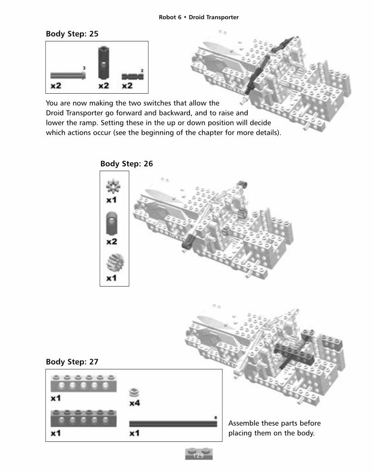
Body Step: 25
You are now making the two switches that allow theDroid Transporter go forward and backward, and to raise andlower the ramp. Setting these in the up or down position will decidewhich actions occur (see the beginning of the chapter for more details).
Body Step: 26
Body Step: 27
Assemble these parts beforeplacing them on the body.
Robot 6 • Droid Transporter
130
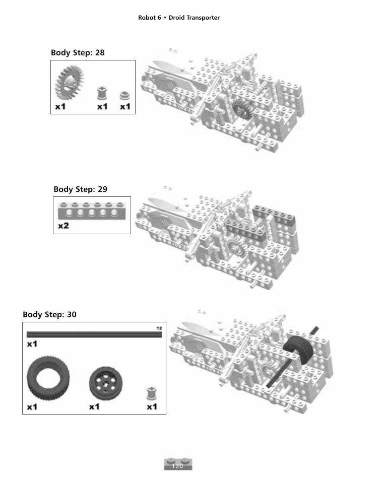
Body Step: 28
Body Step: 29
Body Step: 30
Robot 6 • Droid Transporter
131
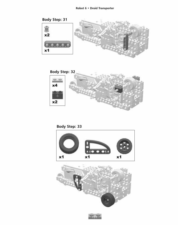
Body Step: 31
Body Step: 32
Body Step: 33
Robot 6 • Droid Transporter
132
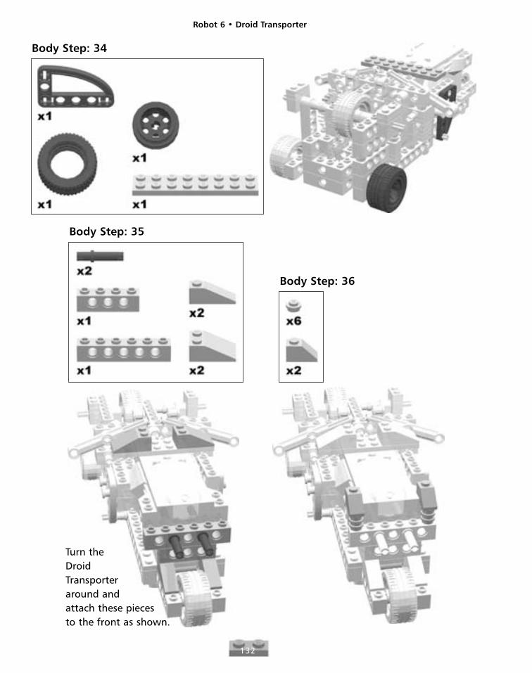
Body Step: 34
Body Step: 35
Body Step: 36
Turn the DroidTransporteraround andattach these piecesto the front as shown.
Robot 6 • Droid Transporter
133
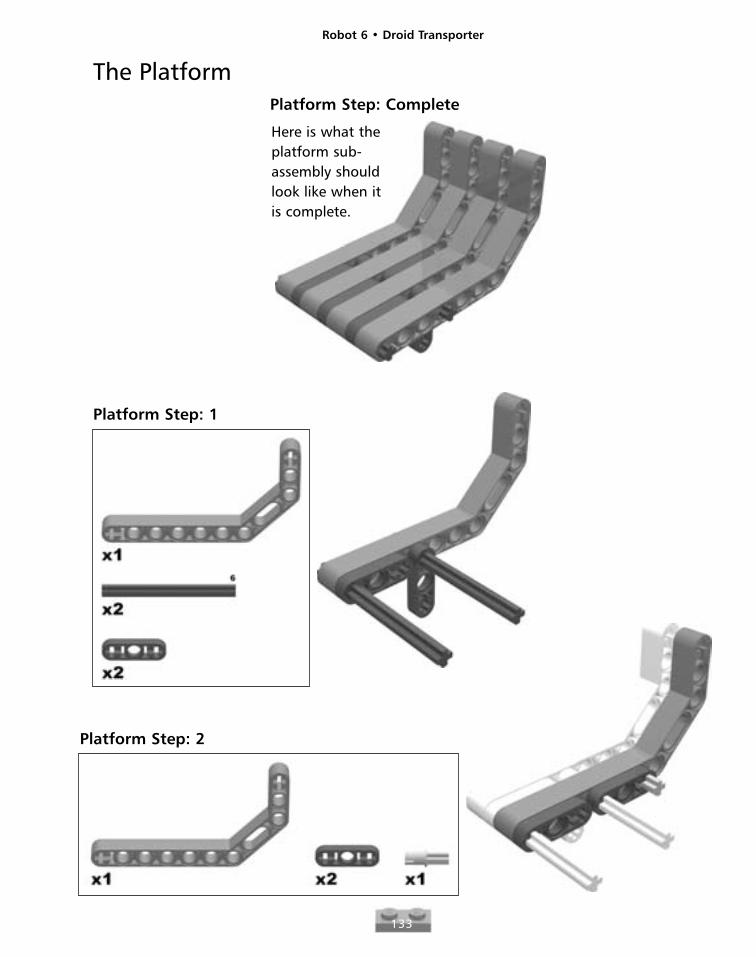
The PlatformPlatform Step: Complete
Here is what theplatform sub-assembly shouldlook like when it is complete.
Platform Step: 1
Platform Step: 2
Robot 6 • Droid Transporter
134
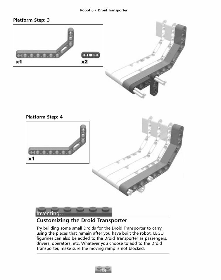
Platform Step: 3
Platform Step: 4
Inventing…Customizing the Droid TransporterTry building some small Droids for the Droid Transporter to carry,using the pieces that remain after you have built the robot. LEGOfigurines can also be added to the Droid Transporter as passengers,drivers, operators, etc. Whatever you choose to add to the DroidTransporter, make sure the moving ramp is not blocked.
Robot 6 • Droid Transporter
135
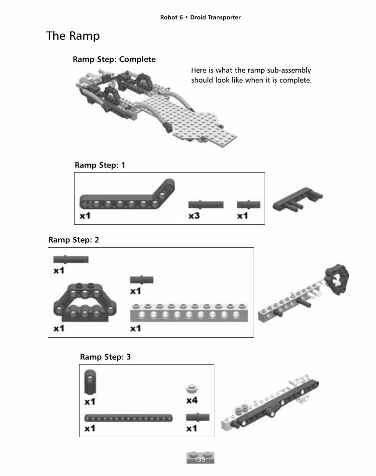
Ramp Step: Complete
The Ramp
Here is what the ramp sub-assemblyshould look like when it is complete.
Ramp Step: 1
Ramp Step: 2
Ramp Step: 3
Robot 6 • Droid Transporter
136
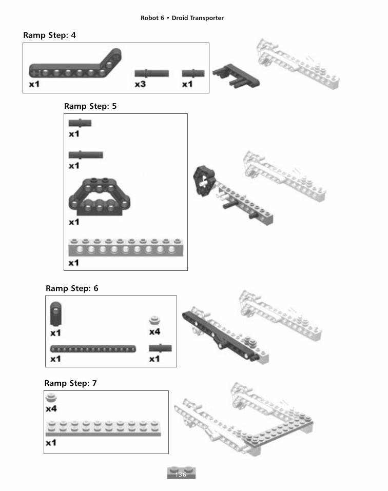
Ramp Step: 4
Ramp Step: 5
Ramp Step: 6
Ramp Step: 7
Robot 6 • Droid Transporter
137
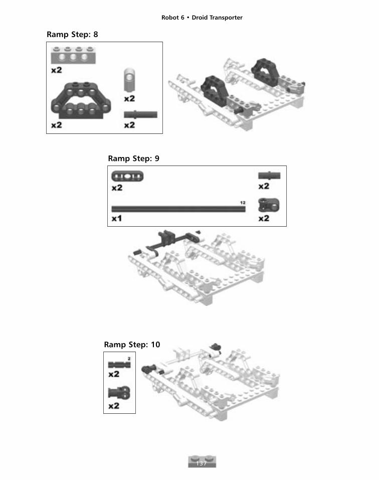
Ramp Step: 8
Ramp Step: 9
Ramp Step: 10
Robot 6 • Droid Transporter
138
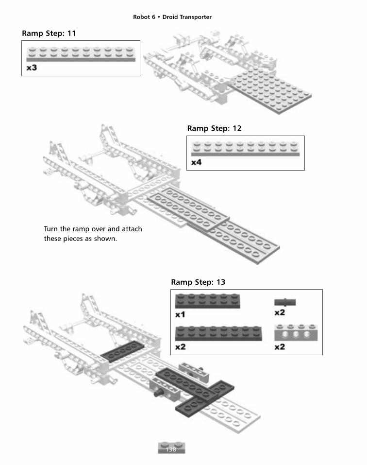
Ramp Step: 11
Ramp Step: 12
Ramp Step: 13
Turn the ramp over and attachthese pieces as shown.
Robot 6 • Droid Transporter
139
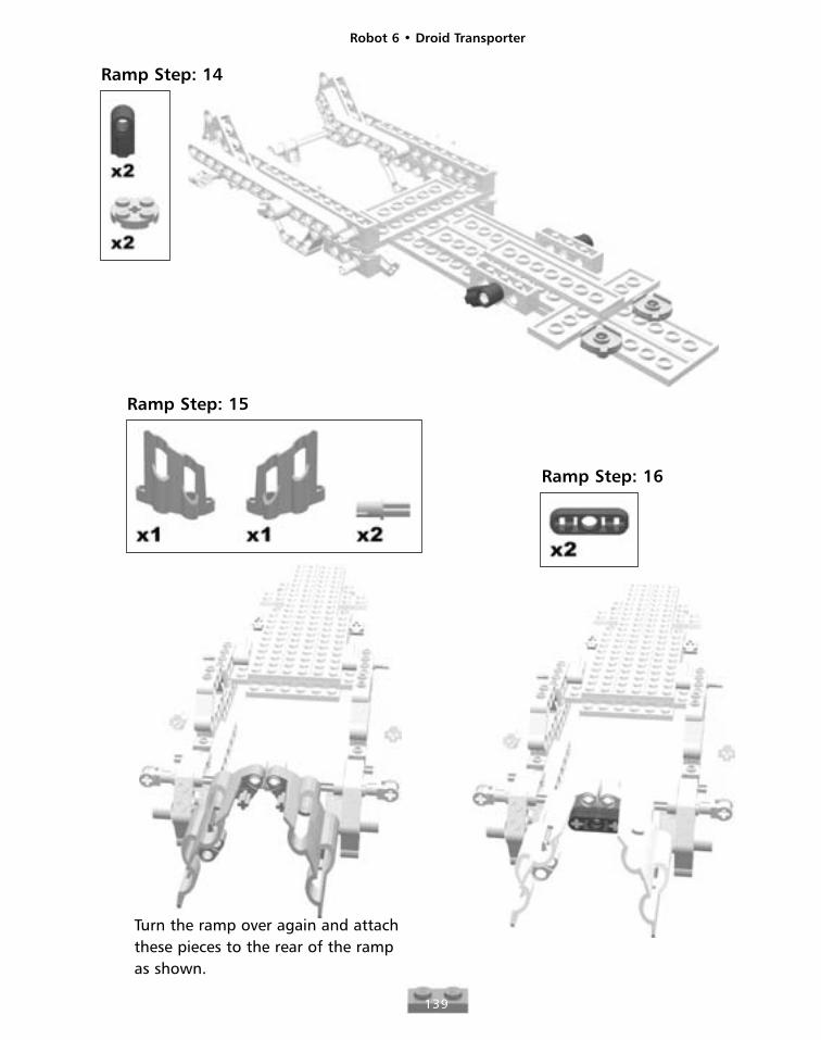
Ramp Step: 14
Ramp Step: 15
Turn the ramp over again and attachthese pieces to the rear of the rampas shown.
Ramp Step: 16

Robot 6 • Droid Transporter
140
Ramp Step: 17
Ramp Step: 18
Robot 6 • Droid Transporter
141
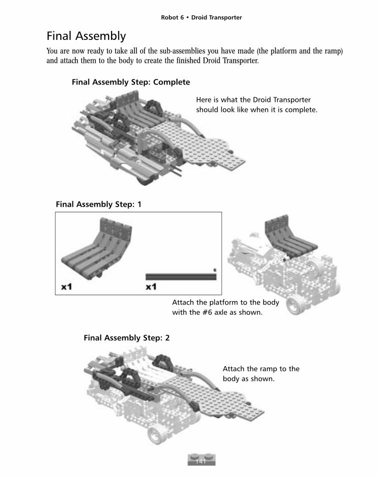
Final AssemblyYou are now ready to take all of the sub-assemblies you have made (the platform and the ramp)and attach them to the body to create the finished Droid Transporter.
Final Assembly Step: Complete
Here is what the Droid Transportershould look like when it is complete.
Final Assembly Step: 1
Attach the platform to the bodywith the #6 axle as shown.
Final Assembly Step: 2
Attach the ramp to thebody as shown.
Robot 6 • Droid Transporter
142
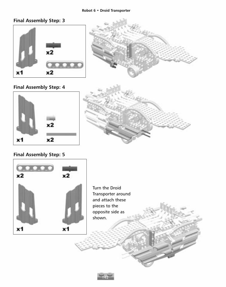
Final Assembly Step: 3
Final Assembly Step: 4
Final Assembly Step: 5
Turn the DroidTransporter aroundand attach thesepieces to theopposite side asshown.
Robot 6 • Droid Transporter
143
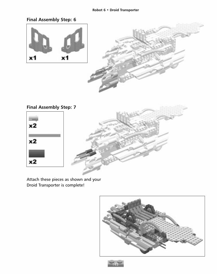
Final Assembly Step: 6
Final Assembly Step: 7
Attach these pieces as shown and yourDroid Transporter is complete!

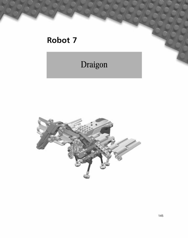
Robot 7
145
Draigon
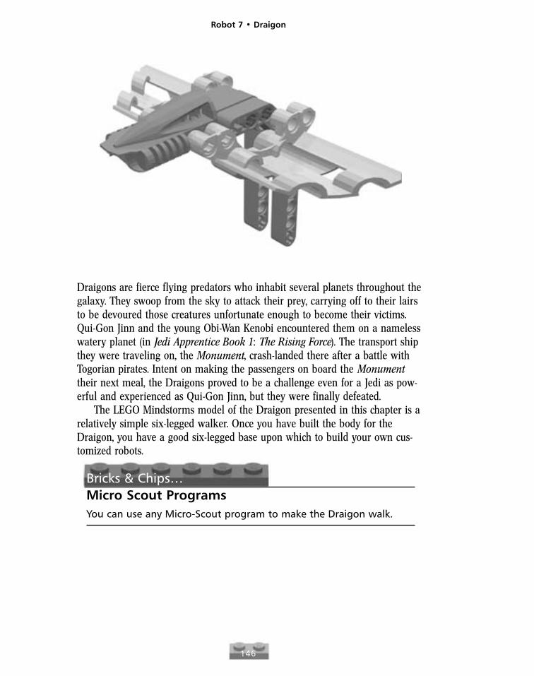
Draigons are fierce flying predators who inhabit several planets throughout thegalaxy. They swoop from the sky to attack their prey, carrying off to their lairsto be devoured those creatures unfortunate enough to become their victims.Qui-Gon Jinn and the young Obi-Wan Kenobi encountered them on a namelesswatery planet (in Jedi Apprentice Book 1: The Rising Force). The transport shipthey were traveling on, the Monument, crash-landed there after a battle withTogorian pirates. Intent on making the passengers on board the Monumenttheir next meal, the Draigons proved to be a challenge even for a Jedi as pow-erful and experienced as Qui-Gon Jinn, but they were finally defeated.
The LEGO Mindstorms model of the Draigon presented in this chapter is arelatively simple six-legged walker. Once you have built the body for theDraigon, you have a good six-legged base upon which to build your own cus-tomized robots.
Bricks & Chips…Micro Scout ProgramsYou can use any Micro-Scout program to make the Draigon walk.
Robot 7 • Draigon
146
Robot 7 • Draigon
147
Body Step: Complete
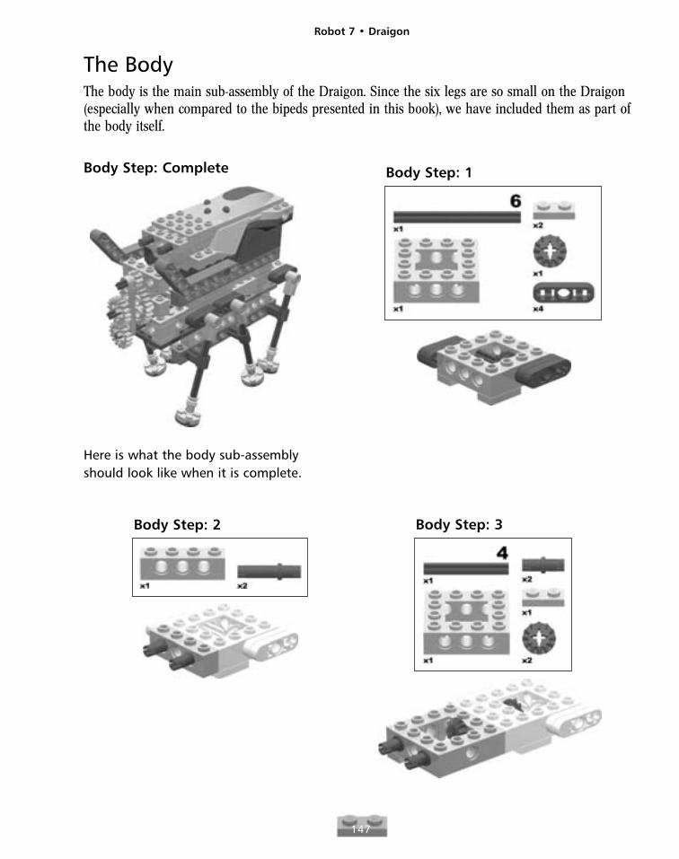
The BodyThe body is the main sub-assembly of the Draigon. Since the six legs are so small on the Draigon(especially when compared to the bipeds presented in this book), we have included them as part ofthe body itself.
Here is what the body sub-assemblyshould look like when it is complete.
Body Step: 1
Body Step: 2 Body Step: 3
Robot 7 • Draigon
148
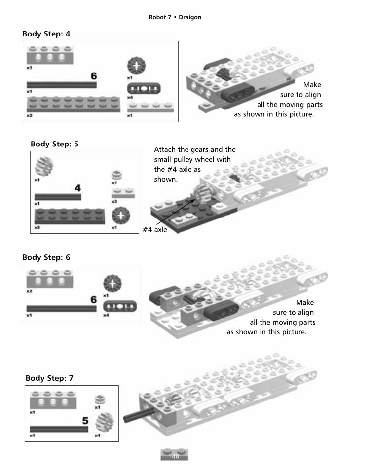
Body Step: 4
Body Step: 5
Makesure to align
all the moving partsas shown in this picture.
Attach the gears and thesmall pulley wheel withthe #4 axle asshown.
#4 axle
Body Step: 6
Makesure to align
all the moving partsas shown in this picture.
Body Step: 7
Robot 7 • Draigon
149
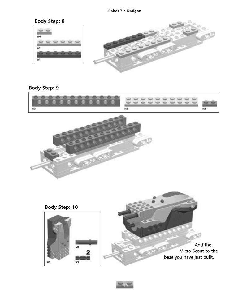
Body Step: 8
Body Step: 9
Body Step: 10
Add theMicro Scout to the
base you have just built.
Robot 7 • Draigon
150
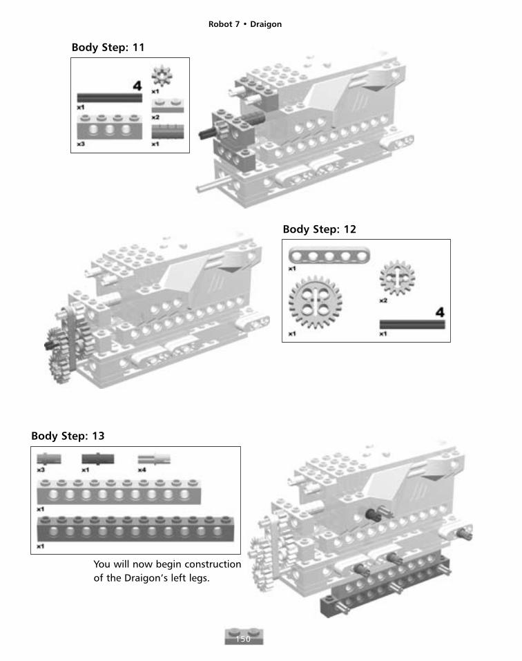
Body Step: 11
Body Step: 12
Body Step: 13
You will now begin constructionof the Draigon’s left legs.
Robot 7 • Draigon
151
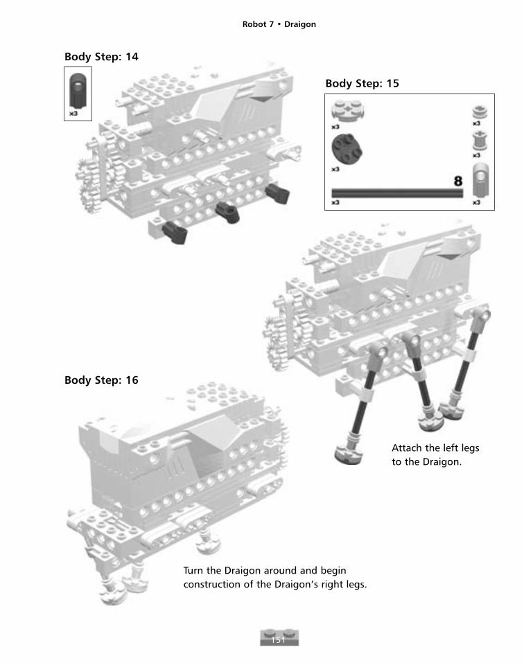
Body Step: 15
Body Step: 14
Attach the left legsto the Draigon.
Turn the Draigon around and beginconstruction of the Draigon’s right legs.
Body Step: 16
Robot 7 • Draigon
152
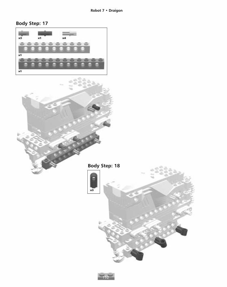
Body Step: 17
Body Step: 18
Robot 7 • Draigon
153
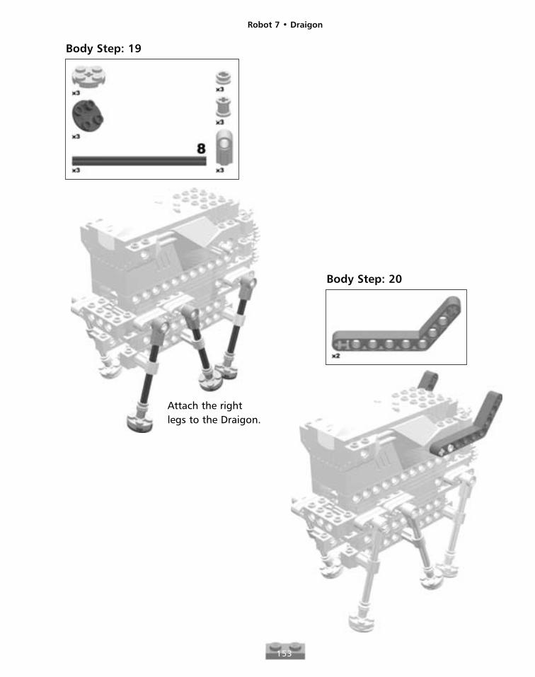
Body Step: 19
Attach the rightlegs to the Draigon.
Body Step: 20
Robot 7 • Draigon
154
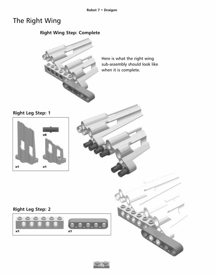
The Right Wing
Right Wing Step: Complete
Here is what the right wingsub-assembly should look likewhen it is complete.
Right Leg Step: 1
Right Leg Step: 2
Robot 7 • Draigon
155
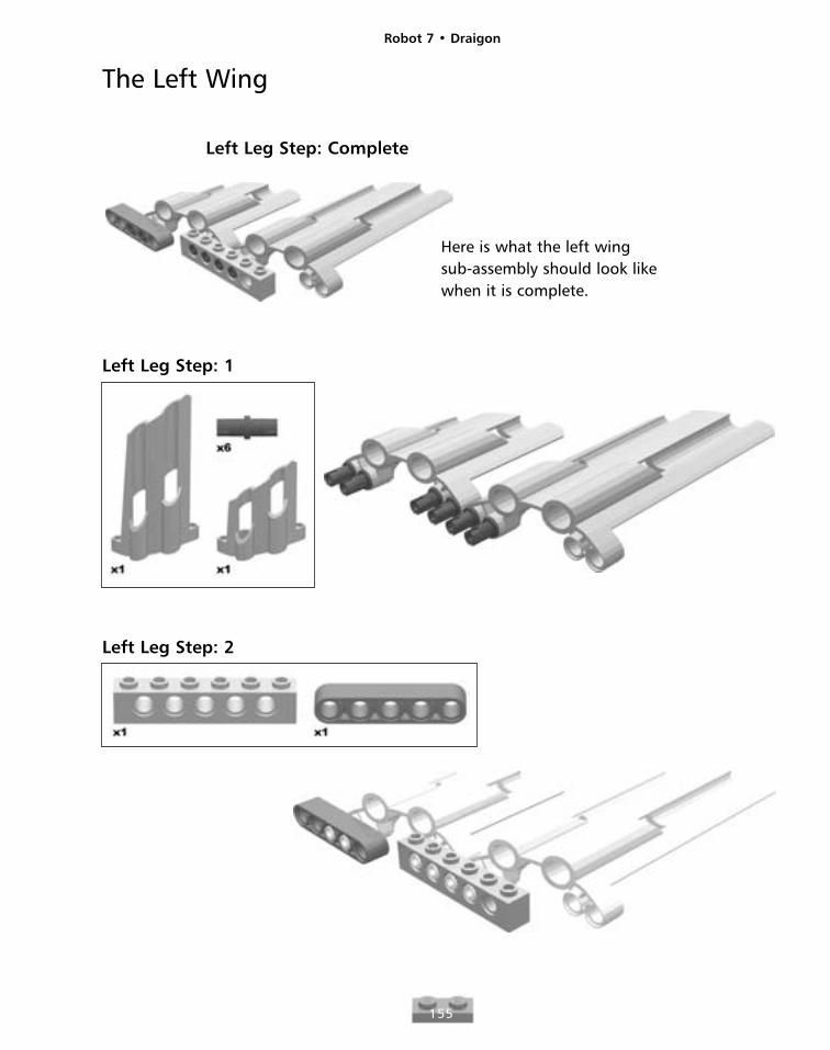
The Left Wing
Left Leg Step: Complete
Here is what the left wingsub-assembly should look likewhen it is complete.
Left Leg Step: 1
Left Leg Step: 2
Robot 7 • Draigon
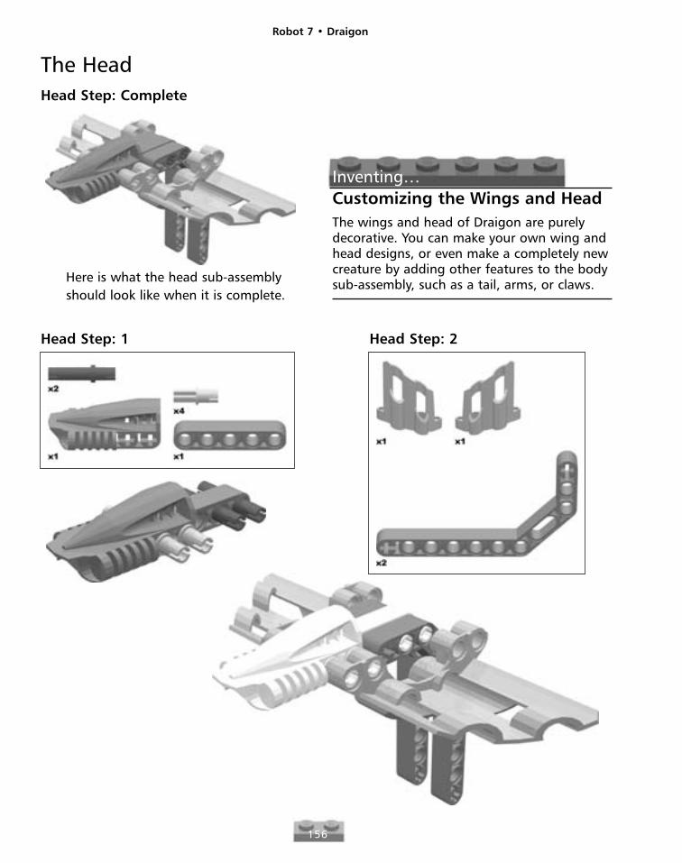
156
The HeadHead Step: Complete
Here is what the head sub-assemblyshould look like when it is complete.
Inventing…Customizing the Wings and HeadThe wings and head of Draigon are purelydecorative. You can make your own wing andhead designs, or even make a completely newcreature by adding other features to the bodysub-assembly, such as a tail, arms, or claws.
Head Step: 1 Head Step: 2
Robot 7 • Draigon
157
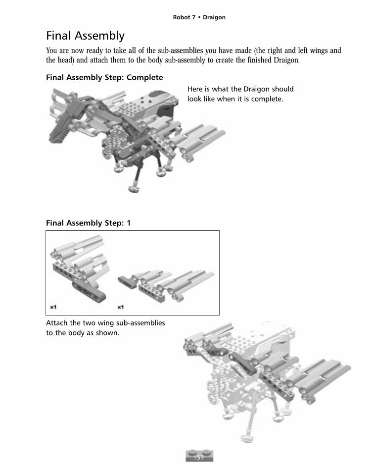
Final AssemblyYou are now ready to take all of the sub-assemblies you have made (the right and left wings andthe head) and attach them to the body sub-assembly to create the finished Draigon.
Final Assembly Step: CompleteHere is what the Draigon shouldlook like when it is complete.
Final Assembly Step: 1
Attach the two wing sub-assembliesto the body as shown.
Robot 7 • Draigon
158
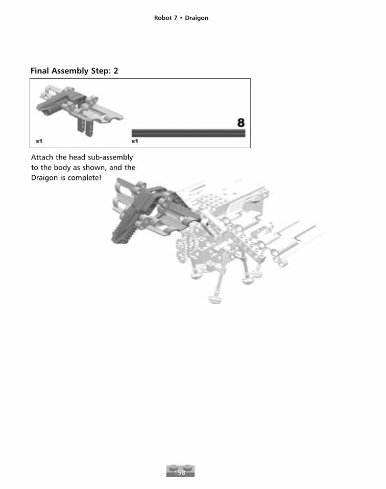
Final Assembly Step: 2
Attach the head sub-assemblyto the body as shown, and theDraigon is complete!
Robot 8
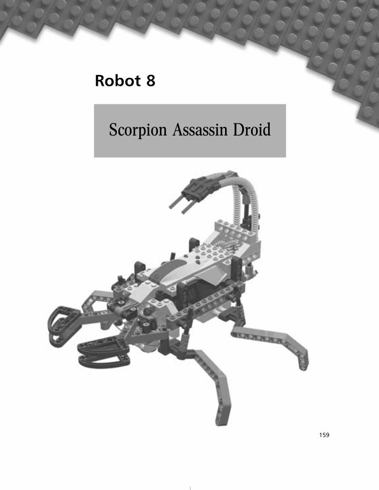
159
Scorpion Assassin Droid
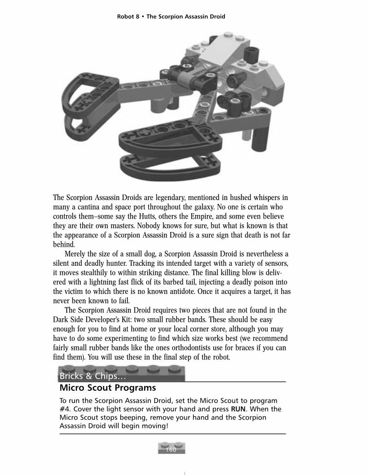
The Scorpion Assassin Droids are legendary, mentioned in hushed whispers inmany a cantina and space port throughout the galaxy. No one is certain whocontrols them—some say the Hutts, others the Empire, and some even believethey are their own masters. Nobody knows for sure, but what is known is thatthe appearance of a Scorpion Assassin Droid is a sure sign that death is not farbehind.
Merely the size of a small dog, a Scorpion Assassin Droid is nevertheless asilent and deadly hunter. Tracking its intended target with a variety of sensors,it moves stealthily to within striking distance. The final killing blow is deliv-ered with a lightning fast flick of its barbed tail, injecting a deadly poison intothe victim to which there is no known antidote. Once it acquires a target, it hasnever been known to fail.
The Scorpion Assassin Droid requires two pieces that are not found in theDark Side Developer’s Kit: two small rubber bands. These should be easyenough for you to find at home or your local corner store, although you mayhave to do some experimenting to find which size works best (we recommendfairly small rubber bands like the ones orthodontists use for braces if you canfind them). You will use these in the final step of the robot.
Bricks & Chips…Micro Scout ProgramsTo run the Scorpion Assassin Droid, set the Micro Scout to program#4. Cover the light sensor with your hand and press RUN. When theMicro Scout stops beeping, remove your hand and the ScorpionAssassin Droid will begin moving!
Robot 8 • The Scorpion Assassin Droid
160
Robot 8 • The Scorpion Assassin Droid
161
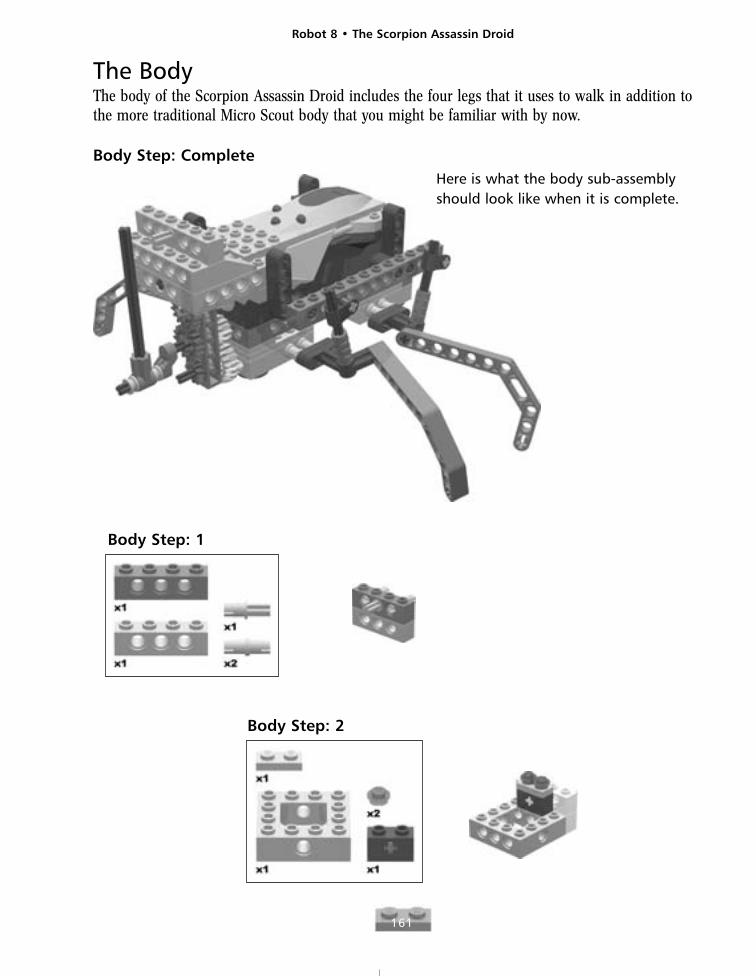
The BodyThe body of the Scorpion Assassin Droid includes the four legs that it uses to walk in addition tothe more traditional Micro Scout body that you might be familiar with by now.
Body Step: Complete
Body Step: 2
Here is what the body sub-assemblyshould look like when it is complete.
Body Step: 1
Robot 8 • The Scorpion Assassin Droid
162
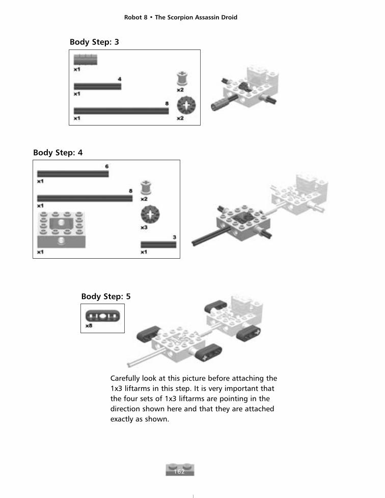
Body Step: 3
Body Step: 4
Carefully look at this picture before attaching the1x3 liftarms in this step. It is very important thatthe four sets of 1x3 liftarms are pointing in thedirection shown here and that they are attachedexactly as shown.
Body Step: 5
Robot 8 • The Scorpion Assassin Droid
163
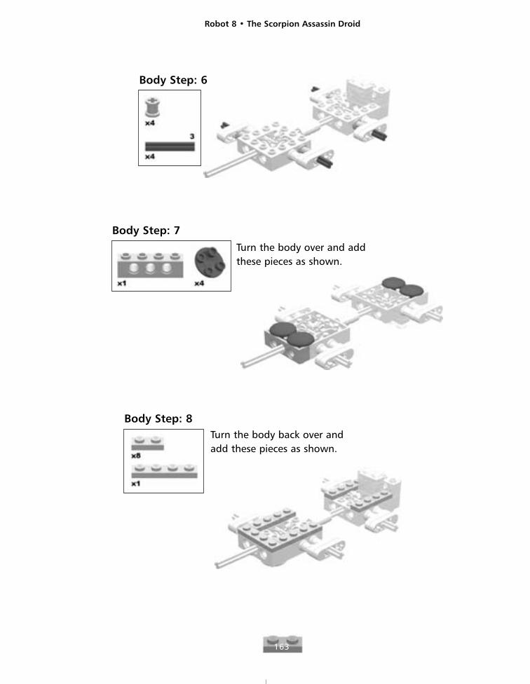
Body Step: 7Turn the body over and addthese pieces as shown.
Body Step: 8Turn the body back over andadd these pieces as shown.
Body Step: 6
Robot 8 • The Scorpion Assassin Droid
164
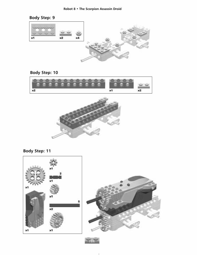
Body Step: 10
Body Step: 11
Body Step: 9
Robot 8 • The Scorpion Assassin Droid
165
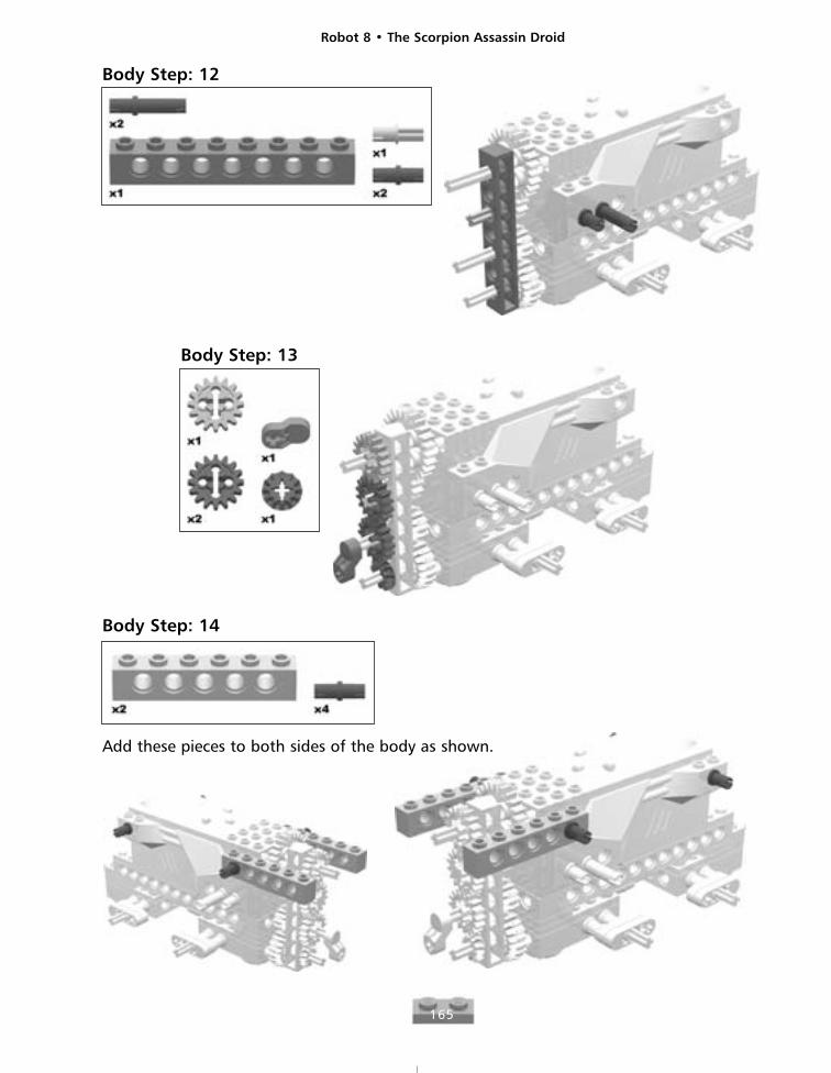
Body Step: 12
Body Step: 13
Body Step: 14
Add these pieces to both sides of the body as shown.
Robot 8 • The Scorpion Assassin Droid
166
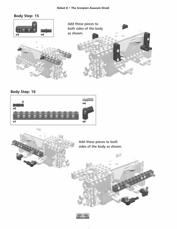
Body Step: 15
Add these pieces toboth sides of the bodyas shown.
Body Step: 16
Add these pieces to bothsides of the body as shown.
Robot 8 • The Scorpion Assassin Droid
167
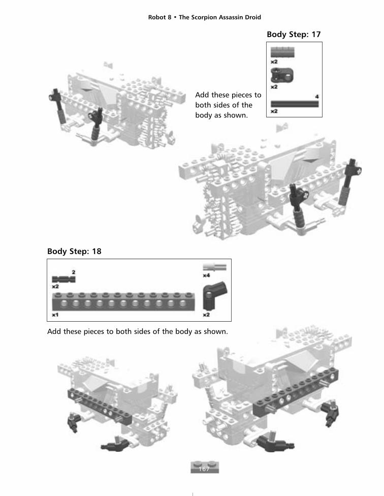
Body Step: 17
Add these pieces toboth sides of thebody as shown.
Body Step: 18
Add these pieces to both sides of the body as shown.
Robot 8 • The Scorpion Assassin Droid
168
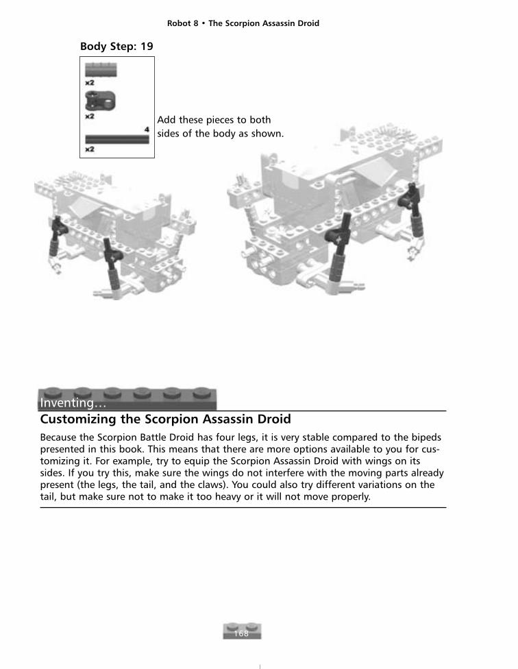
Body Step: 19
Add these pieces to bothsides of the body as shown.
Inventing…Customizing the Scorpion Assassin DroidBecause the Scorpion Battle Droid has four legs, it is very stable compared to the bipedspresented in this book. This means that there are more options available to you for cus-tomizing it. For example, try to equip the Scorpion Assassin Droid with wings on itssides. If you try this, make sure the wings do not interfere with the moving parts alreadypresent (the legs, the tail, and the claws). You could also try different variations on thetail, but make sure not to make it too heavy or it will not move properly.
Robot 8 • The Scorpion Assassin Droid
169
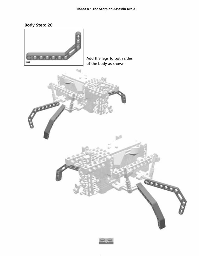
Add the legs to both sidesof the body as shown.
Body Step: 20
Robot 8 • The Scorpion Assassin Droid
170
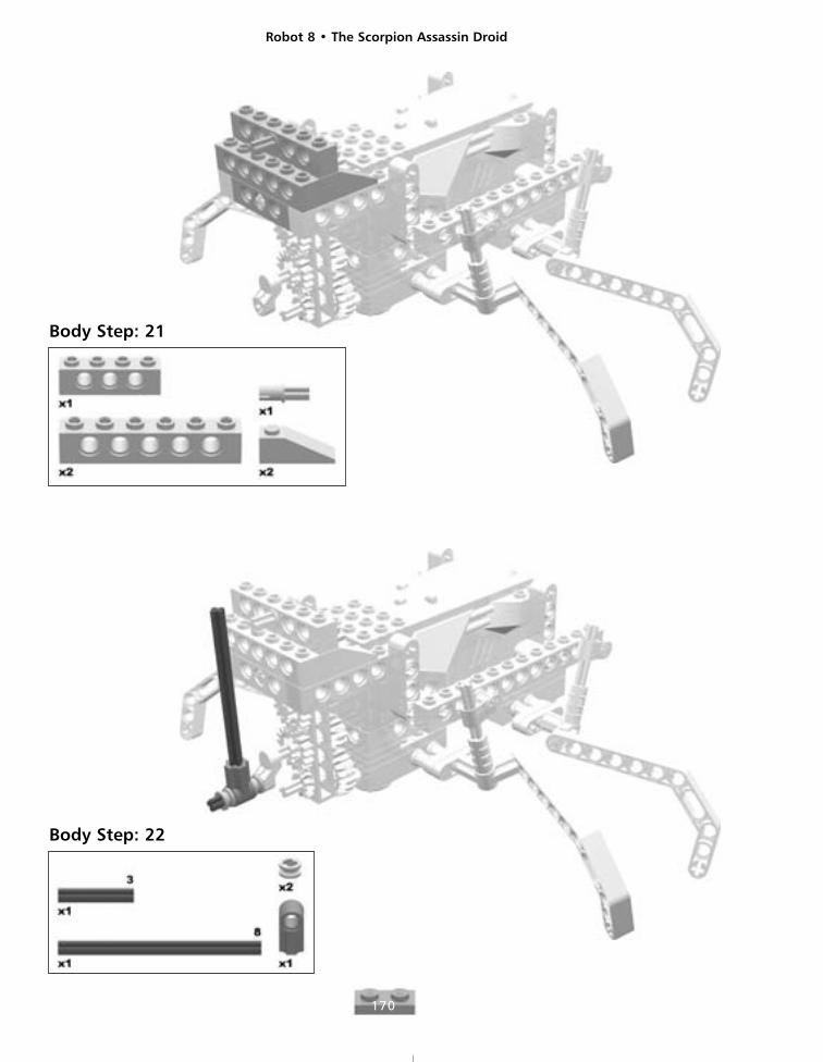
Body Step: 21
Body Step: 22
Robot 8 • The Scorpion Assassin Droid
171
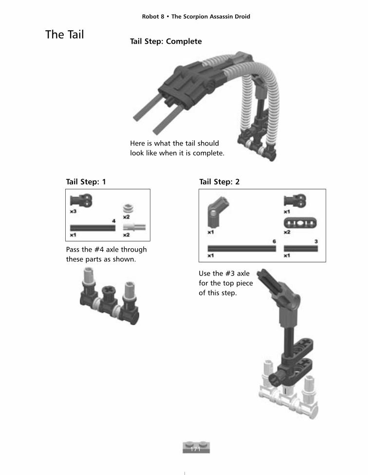
The TailTail Step: Complete
Here is what the tail shouldlook like when it is complete.
Tail Step: 1
Pass the #4 axle throughthese parts as shown.
Tail Step: 2
Use the #3 axlefor the top pieceof this step.
Robot 8 • The Scorpion Assassin Droid
172
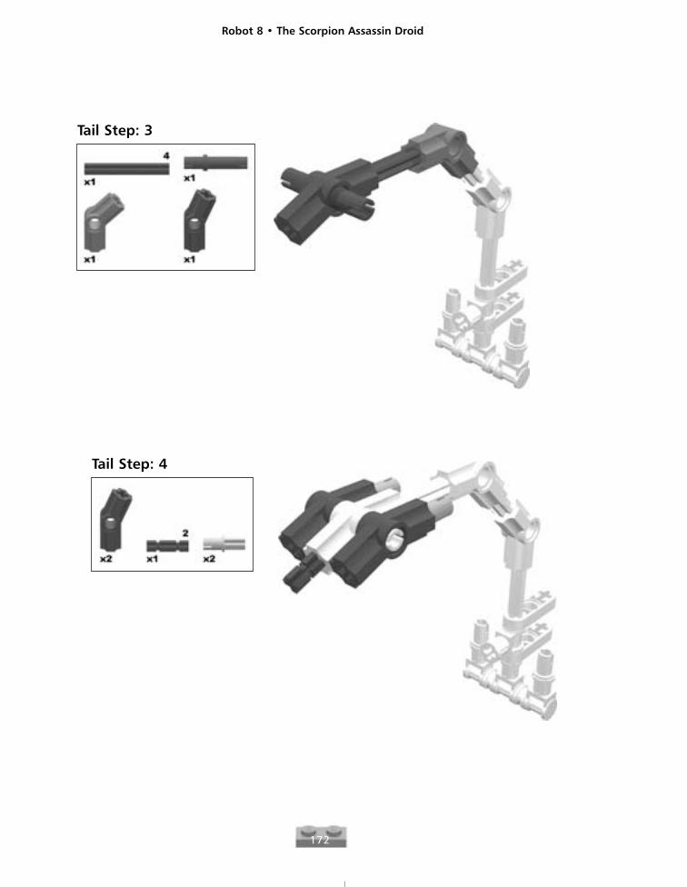
Tail Step: 4
Tail Step: 3
Robot 8 • The Scorpion Assassin Droid
173
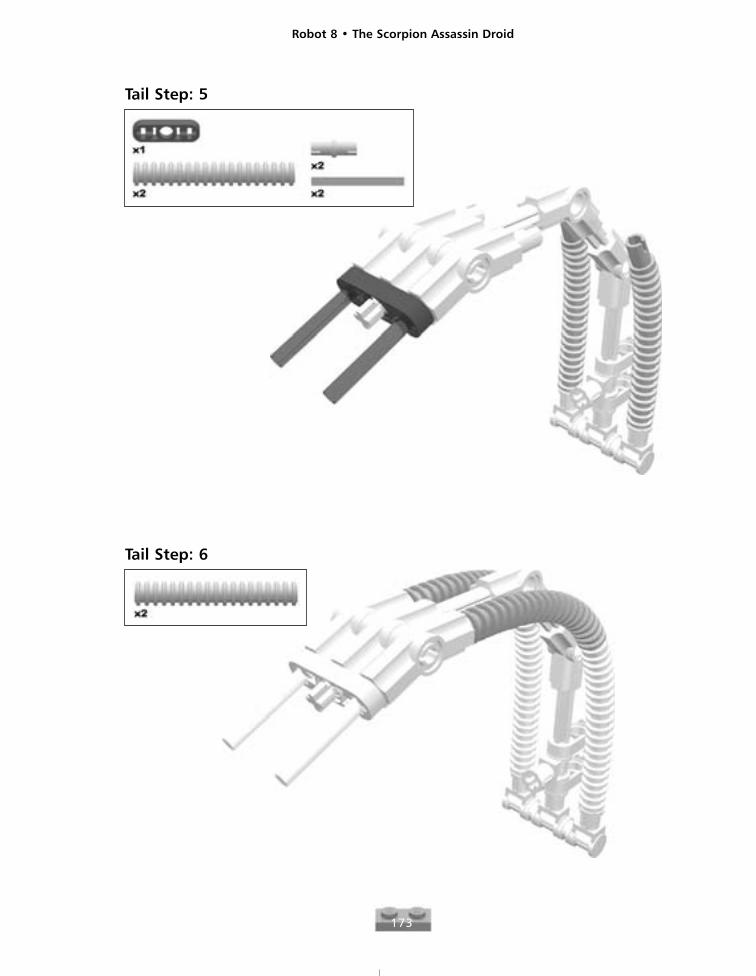
Tail Step: 6
Tail Step: 5
Robot 8 • The Scorpion Assassin Droid
174
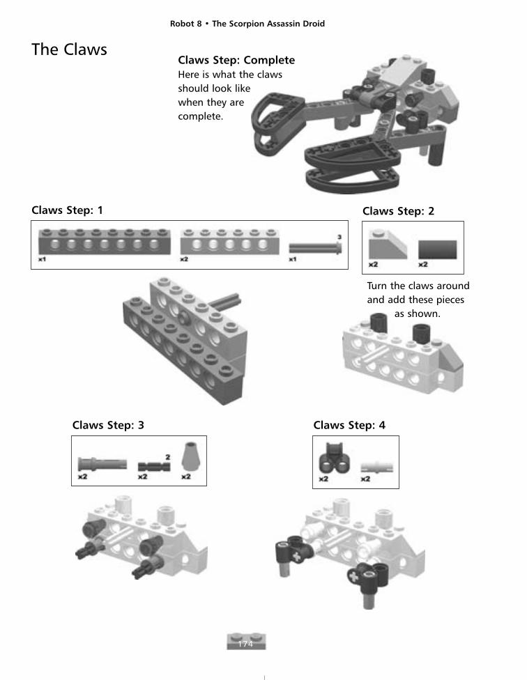
The ClawsClaws Step: CompleteHere is what the clawsshould look like when they are complete.
Claws Step: 1 Claws Step: 2
Turn the claws aroundand add these pieces
as shown.
Claws Step: 3 Claws Step: 4
Robot 8 • The Scorpion Assassin Droid
175
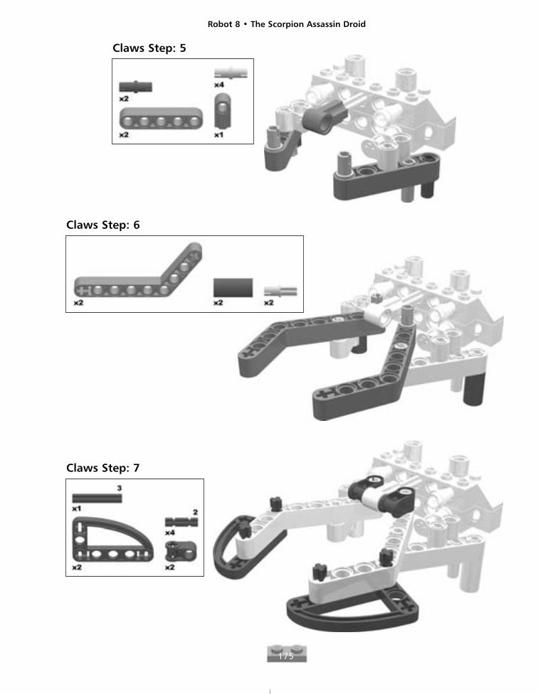
Claws Step: 5
Claws Step: 6
Claws Step: 7
Robot 8 • The Scorpion Assassin Droid
176
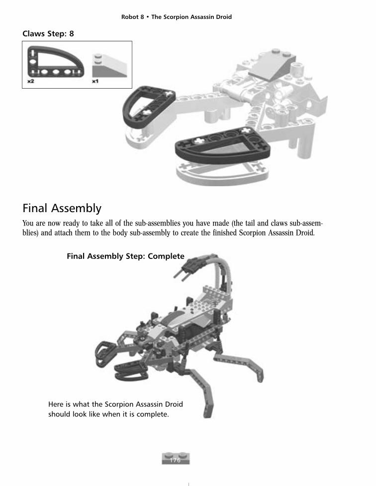
Claws Step: 8
Final AssemblyYou are now ready to take all of the sub-assemblies you have made (the tail and claws sub-assem-blies) and attach them to the body sub-assembly to create the finished Scorpion Assassin Droid.
Final Assembly Step: Complete
Here is what the Scorpion Assassin Droidshould look like when it is complete.
Robot 8 • The Scorpion Assassin Droid
177
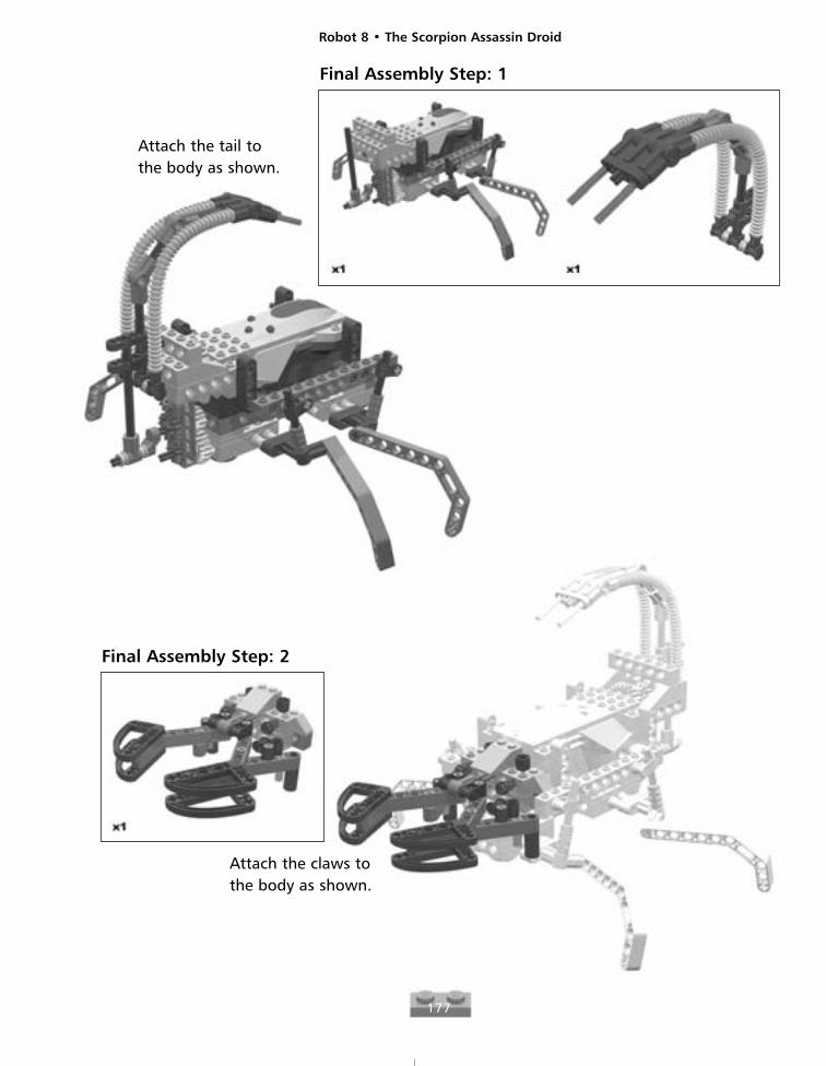
Final Assembly Step: 1
Final Assembly Step: 2
Attach the tail tothe body as shown.
Attach the claws tothe body as shown.
Robot 8 • The Scorpion Assassin Droid
178
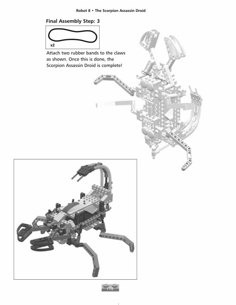
Attach two rubber bands to the clawsas shown. Once this is done, theScorpion Assassin Droid is complete!
Final Assembly Step: 3
Robot 9
179
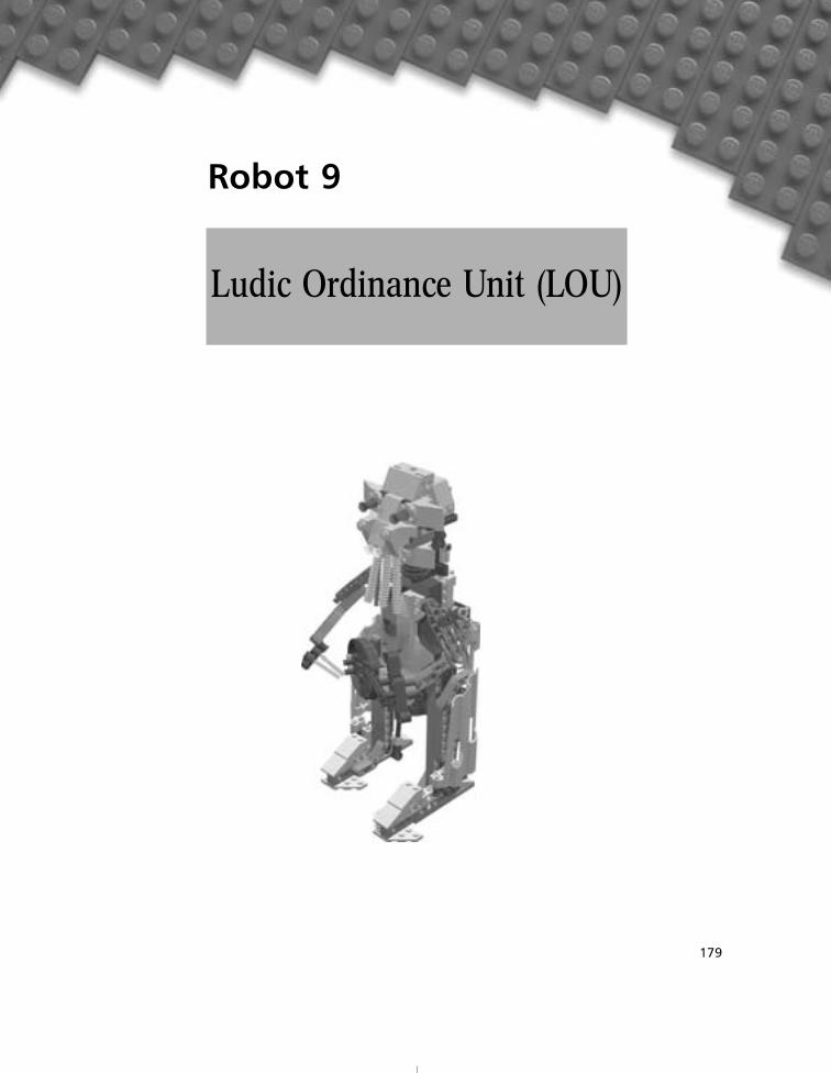
Ludic Ordinance Unit (LOU)
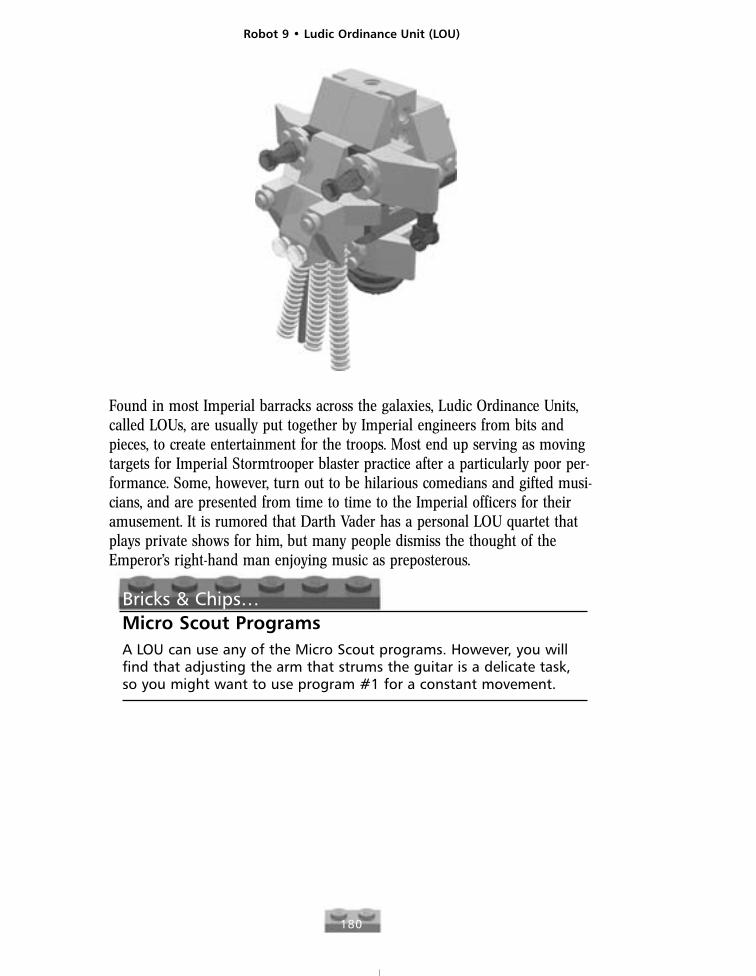
Found in most Imperial barracks across the galaxies, Ludic Ordinance Units,called LOUs, are usually put together by Imperial engineers from bits andpieces, to create entertainment for the troops. Most end up serving as movingtargets for Imperial Stormtrooper blaster practice after a particularly poor per-formance. Some, however, turn out to be hilarious comedians and gifted musi-cians, and are presented from time to time to the Imperial officers for theiramusement. It is rumored that Darth Vader has a personal LOU quartet thatplays private shows for him, but many people dismiss the thought of theEmperor’s right-hand man enjoying music as preposterous.
Bricks & Chips…Micro Scout ProgramsA LOU can use any of the Micro Scout programs. However, you willfind that adjusting the arm that strums the guitar is a delicate task,so you might want to use program #1 for a constant movement.
Robot 9 • Ludic Ordinance Unit (LOU)
180
Robot 9 • Ludic Ordinance Unit (LOU)
181
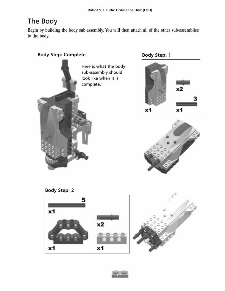
The BodyBegin by building the body sub-assembly. You will then attach all of the other sub-assemblies to the body.
Body Step: Complete
Here is what the bodysub-assembly shouldlook like when it iscomplete.
Body Step: 1
Body Step: 2
Robot 9 • Ludic Ordinance Unit (LOU)
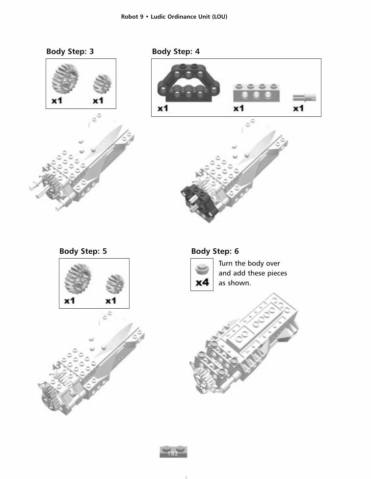
182
Body Step: 3 Body Step: 4
Body Step: 5 Body Step: 6
Turn the body overand add these piecesas shown.
Robot 9 • Ludic Ordinance Unit (LOU)
183
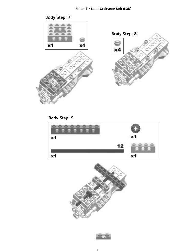
Body Step: 7
Body Step: 8
Body Step: 9
Robot 9 • Ludic Ordinance Unit (LOU)
184
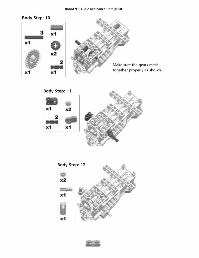
Body Step: 10
Make sure the gears meshtogether properly as shown.
Body Step: 11
Body Step: 12
Robot 9 • Ludic Ordinance Unit (LOU)
185
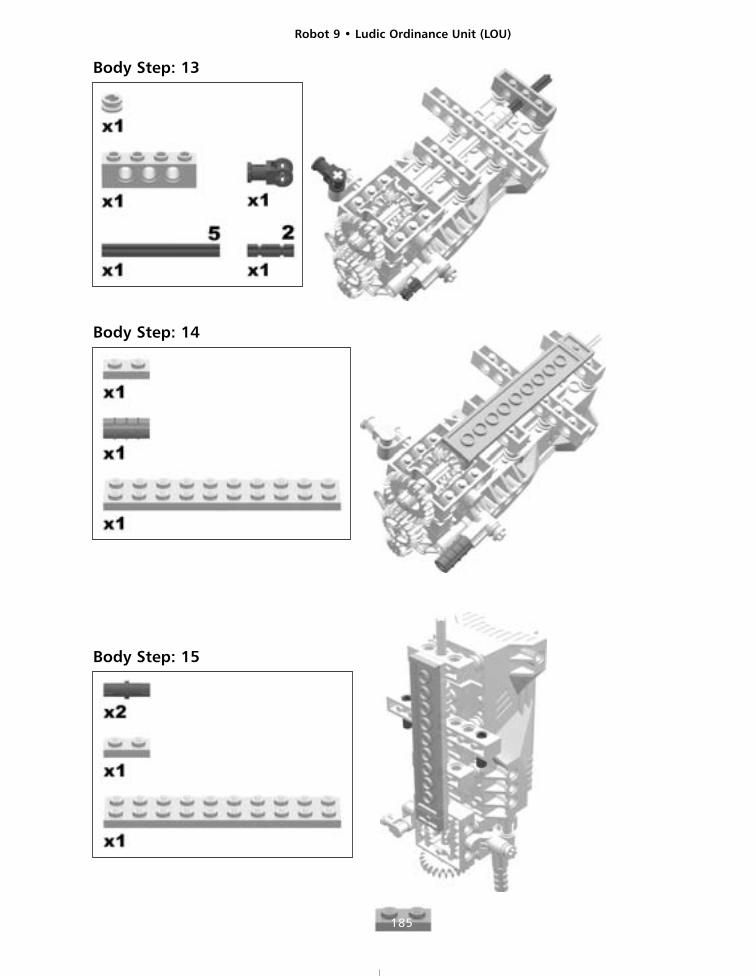
Body Step: 13
Body Step: 14
Body Step: 15
Robot 9 • Ludic Ordinance Unit (LOU)
186
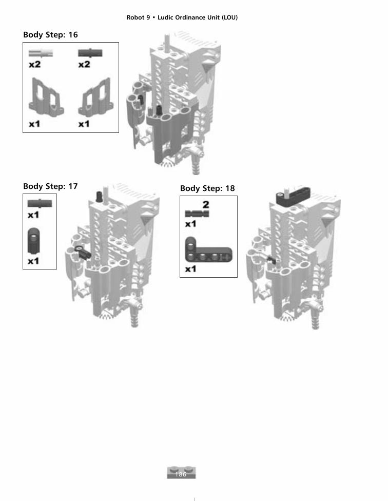
Body Step: 16
Body Step: 17 Body Step: 18
Robot 9 • Ludic Ordinance Unit (LOU)
187
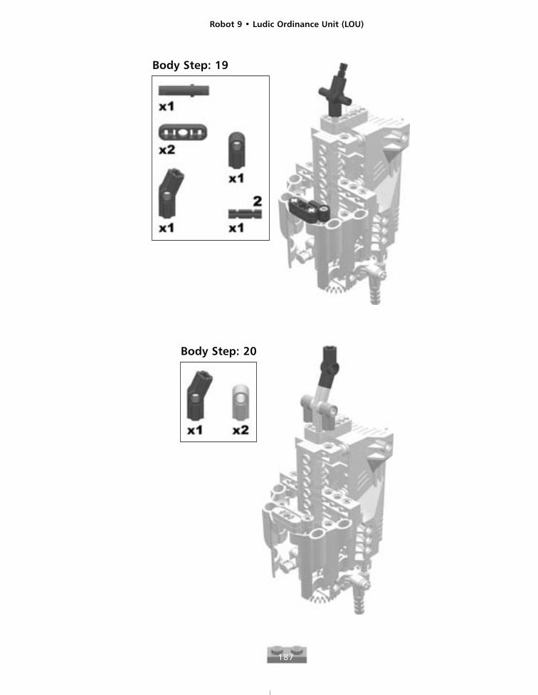
Body Step: 19
Body Step: 20
Robot 9 • Ludic Ordinance Unit (LOU)
188
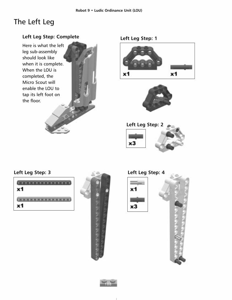
The Left Leg
Left Leg Step: Complete
Here is what the leftleg sub-assemblyshould look likewhen it is complete.When the LOU iscompleted, theMicro Scout willenable the LOU totap its left foot onthe floor.
Left Leg Step: 1
Left Leg Step: 2
Left Leg Step: 3 Left Leg Step: 4
Robot 9 • Ludic Ordinance Unit (LOU)
189
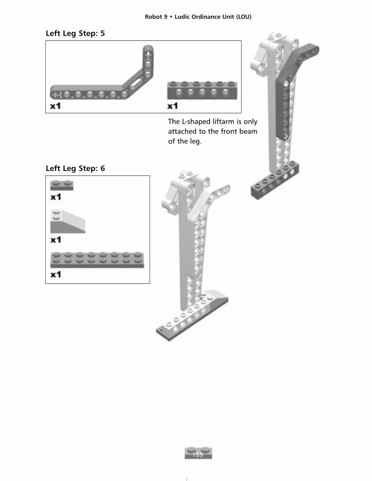
Left Leg Step: 5
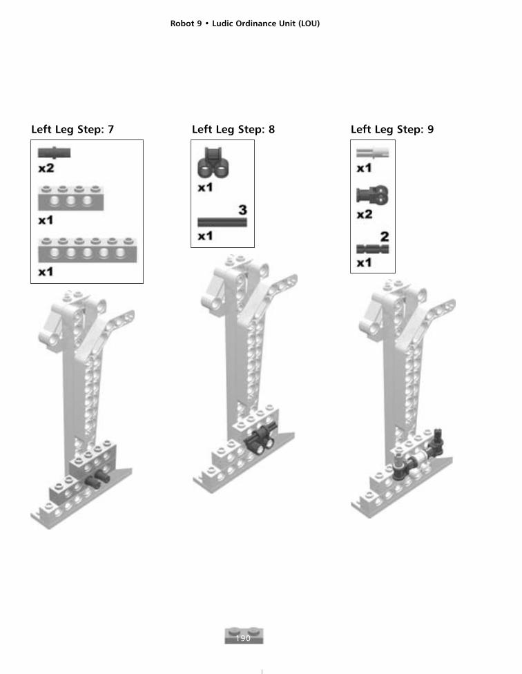
The L-shaped liftarm is onlyattached to the front beamof the leg.
Left Leg Step: 6
Robot 9 • Ludic Ordinance Unit (LOU)
190
Left Leg Step: 7 Left Leg Step: 8 Left Leg Step: 9
Robot 9 • Ludic Ordinance Unit (LOU)
191
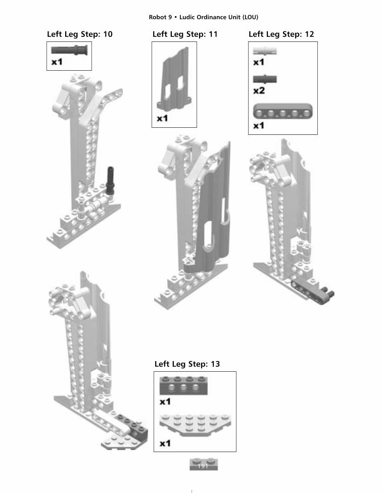
Left Leg Step: 10 Left Leg Step: 11 Left Leg Step: 12
Left Leg Step: 13
Robot 9 • Ludic Ordinance Unit (LOU)
192
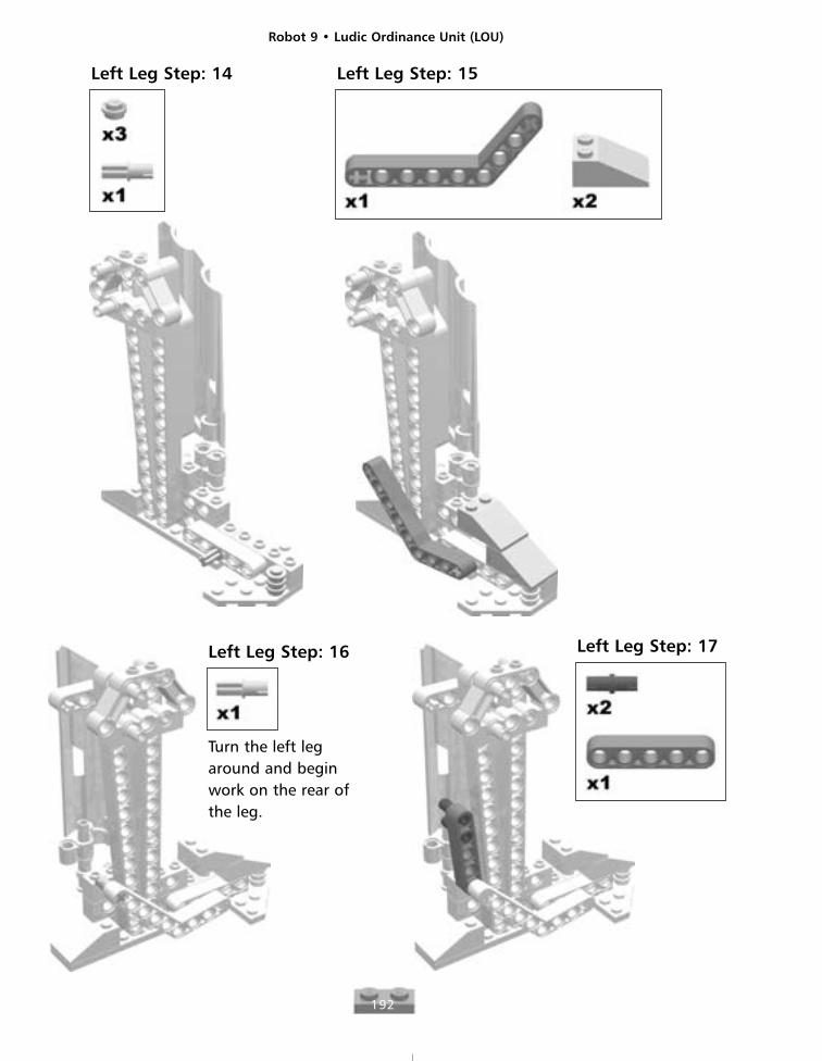
Left Leg Step: 14 Left Leg Step: 15
Left Leg Step: 16
Turn the left legaround and beginwork on the rear ofthe leg.
Left Leg Step: 17
Robot 9 • Ludic Ordinance Unit (LOU)
193
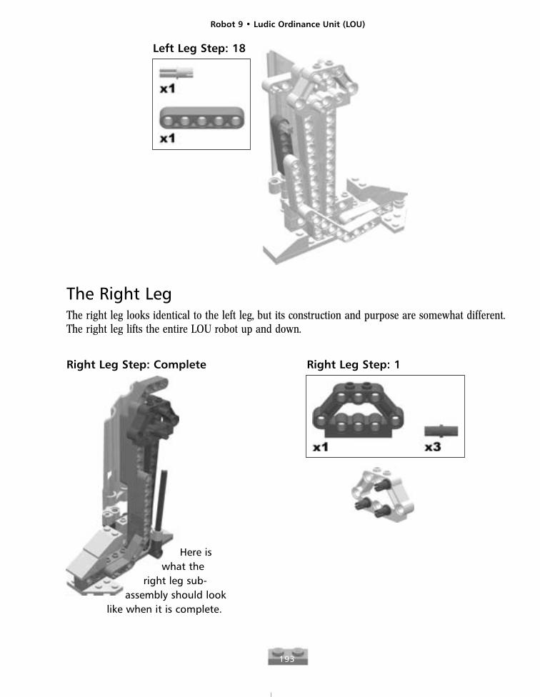
Left Leg Step: 18
Right Leg Step: Complete
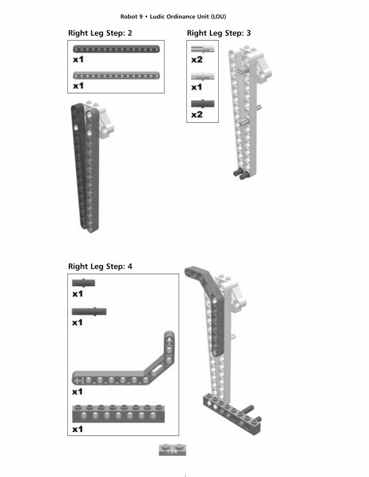
The Right LegThe right leg looks identical to the left leg, but its construction and purpose are somewhat different.The right leg lifts the entire LOU robot up and down.
Right Leg Step: 1
Here iswhat the
right leg sub-assembly should look
like when it is complete.
Robot 9 • Ludic Ordinance Unit (LOU)
194
Right Leg Step: 2 Right Leg Step: 3
Right Leg Step: 4
Robot 9 • Ludic Ordinance Unit (LOU)
195
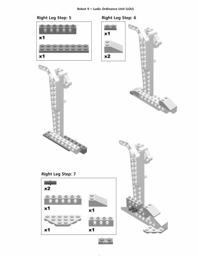
Right Leg Step: 5 Right Leg Step: 6
Right Leg Step: 7
Robot 9 • Ludic Ordinance Unit (LOU)
196
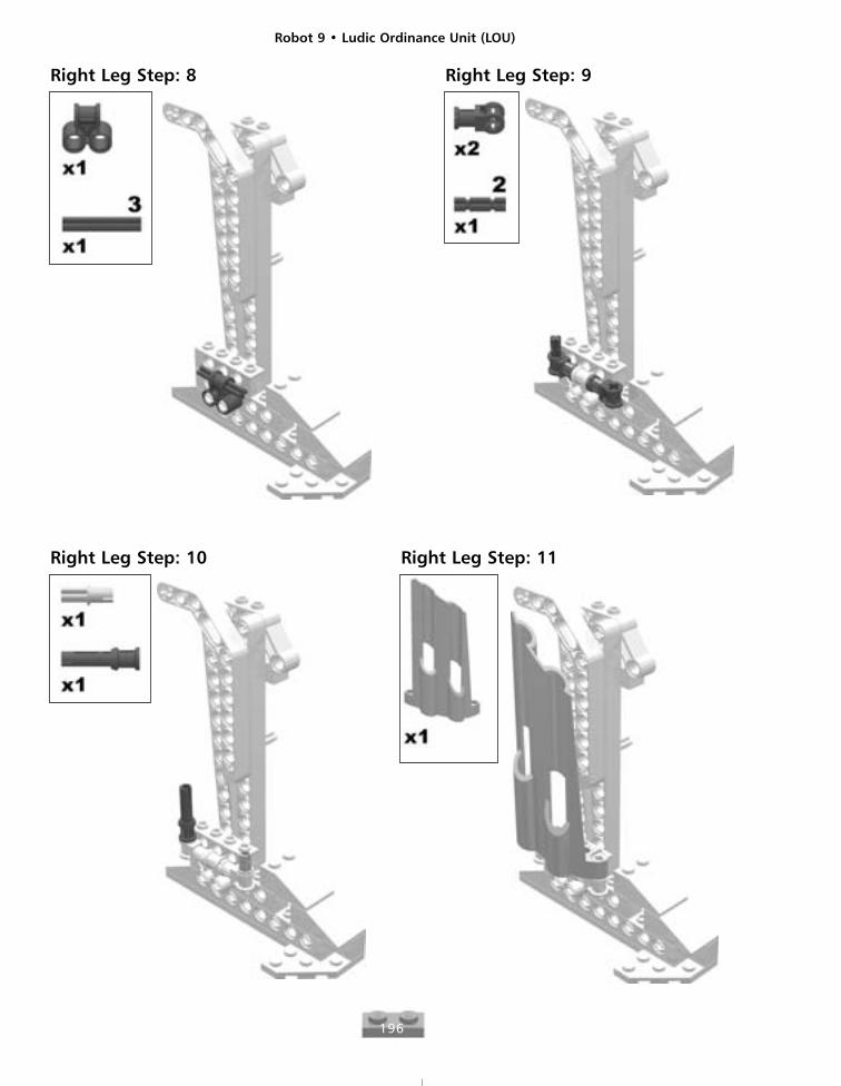
Right Leg Step: 8 Right Leg Step: 9
Right Leg Step: 10 Right Leg Step: 11
Robot 9 • Ludic Ordinance Unit (LOU)
197
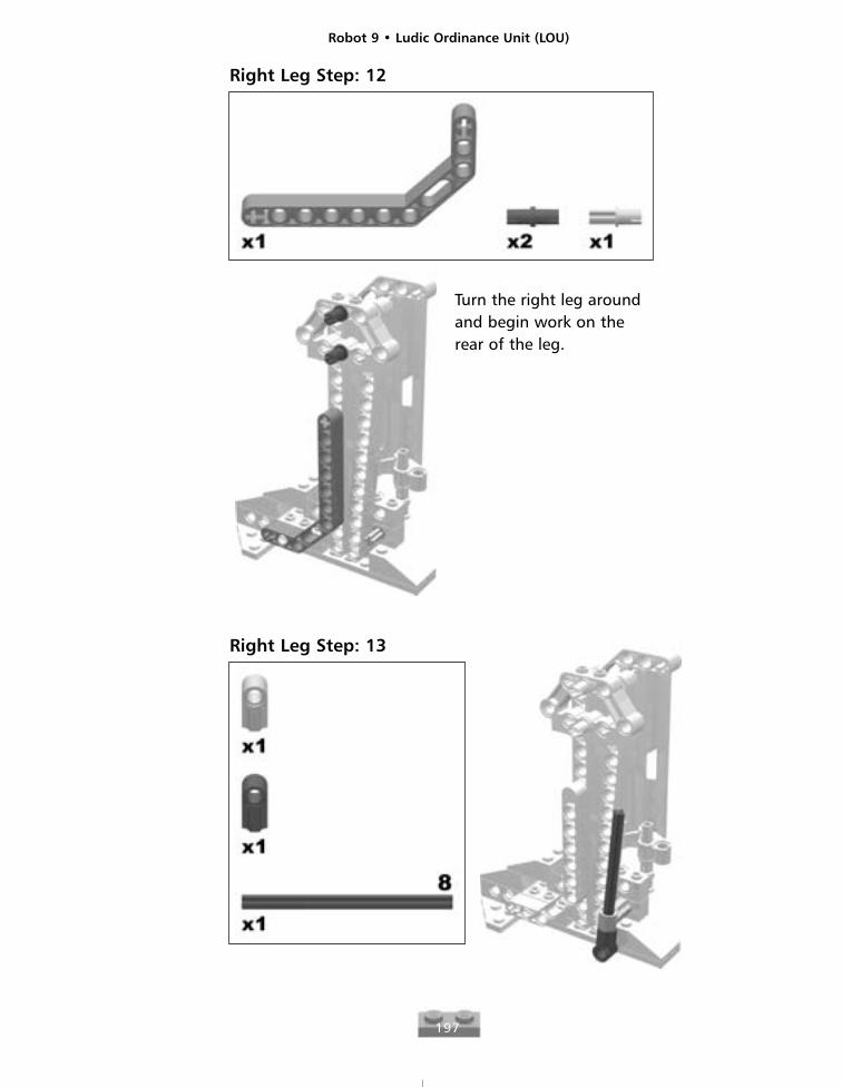
Right Leg Step: 12
Turn the right leg aroundand begin work on therear of the leg.
Right Leg Step: 13
Robot 9 • Ludic Ordinance Unit (LOU)
198
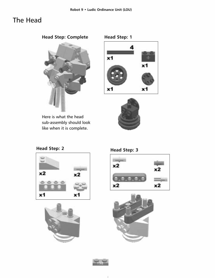
The Head
Head Step: Complete
Here is what the headsub-assembly should looklike when it is complete.
Head Step: 1
Head Step: 2 Head Step: 3
Robot 9 • Ludic Ordinance Unit (LOU)
199
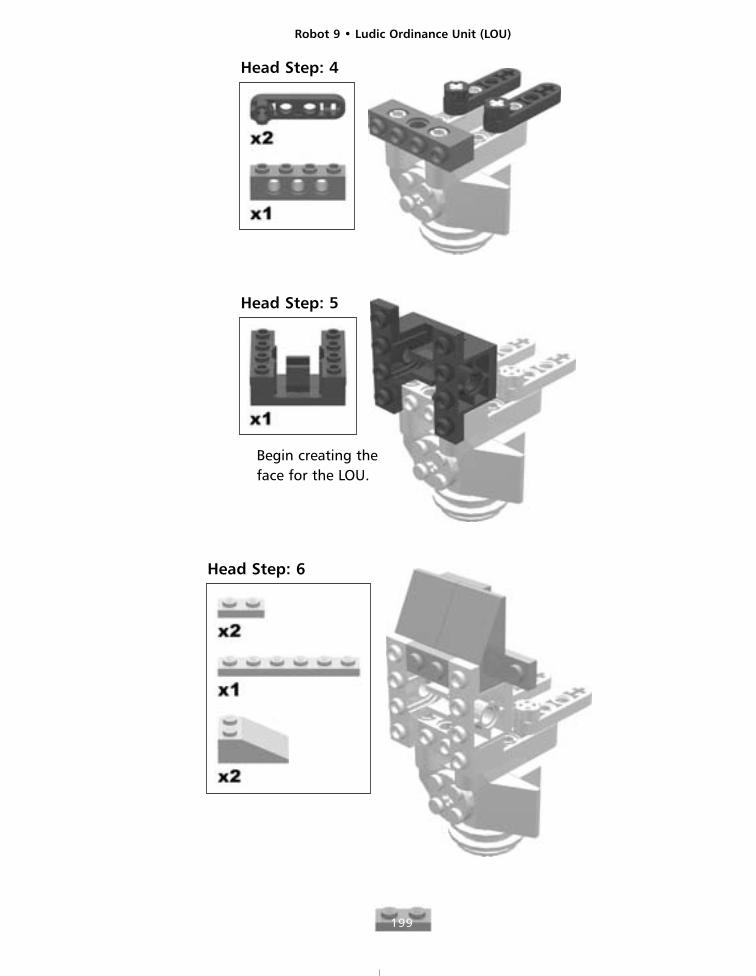
Head Step: 4
Head Step: 5
Begin creating theface for the LOU.
Head Step: 6
Robot 9 • Ludic Ordinance Unit (LOU)
200
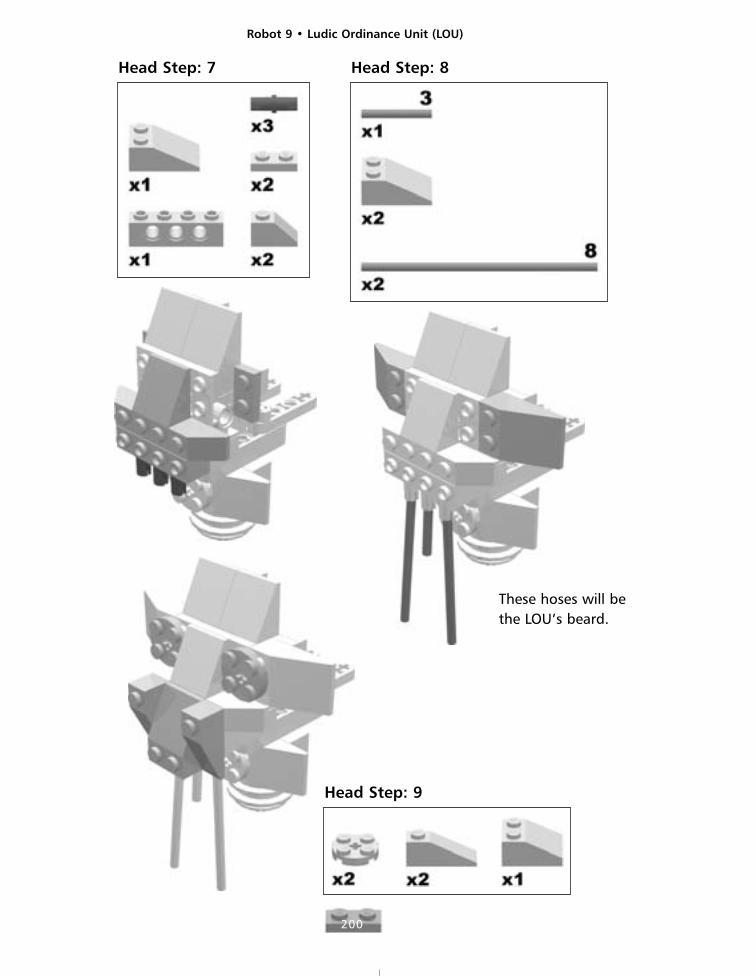
Head Step: 7 Head Step: 8
These hoses will bethe LOU’s beard.
Head Step: 9
Robot 9 • Ludic Ordinance Unit (LOU)
201
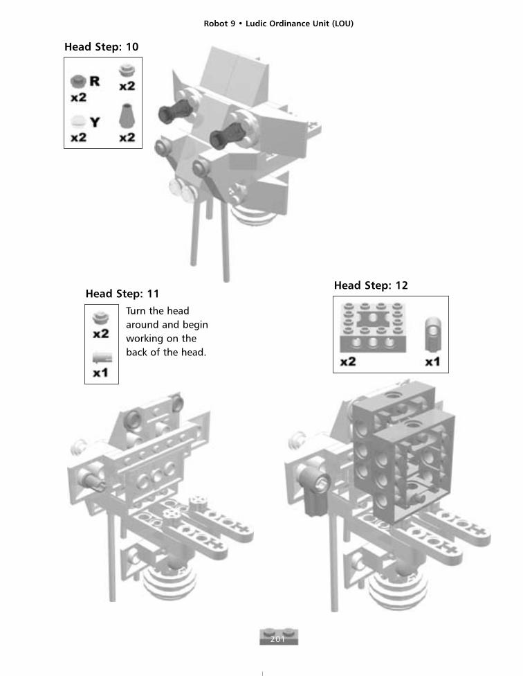
Head Step: 10
Head Step: 11
Turn the headaround and beginworking on theback of the head.
Head Step: 12
Robot 9 • Ludic Ordinance Unit (LOU)
202
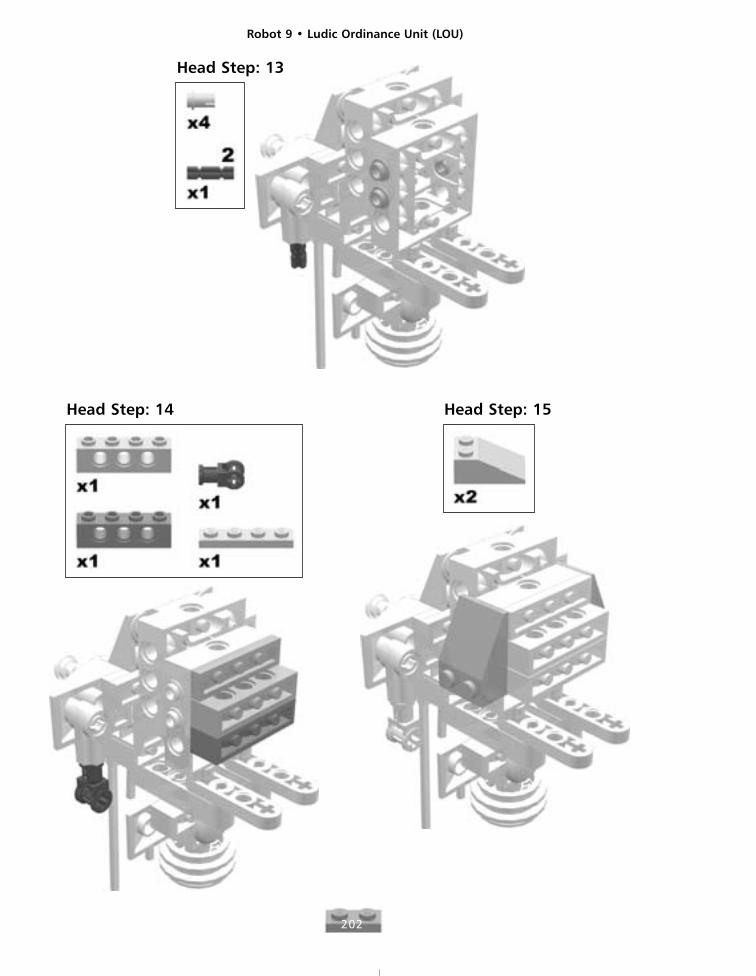
Head Step: 13
Head Step: 14 Head Step: 15
Robot 9 • Ludic Ordinance Unit (LOU)
203
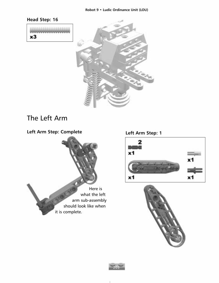
Head Step: 16
The Left Arm
Left Arm Step: Complete
Here iswhat the left
arm sub-assemblyshould look like when
it is complete.
Left Arm Step: 1
Robot 9 • Ludic Ordinance Unit (LOU)
204
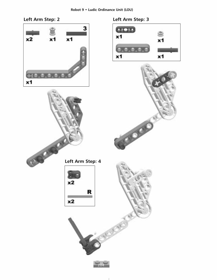
Left Arm Step: 2 Left Arm Step: 3
Left Arm Step: 4
Robot 9 • Ludic Ordinance Unit (LOU)
205
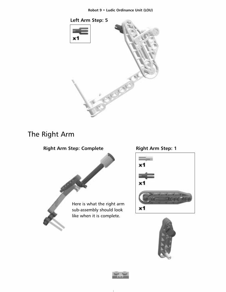
Left Arm Step: 5
The Right Arm
Right Arm Step: Complete
Here is what the right armsub-assembly should looklike when it is complete.
Right Arm Step: 1
Robot 9 • Ludic Ordinance Unit (LOU)
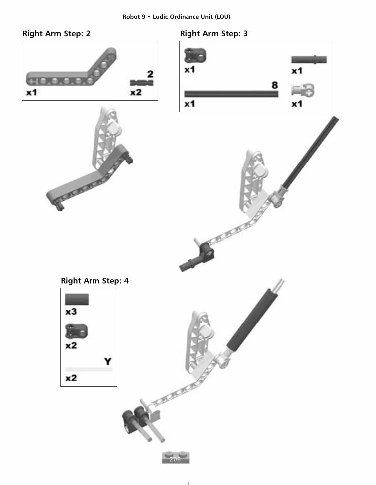
206
Right Arm Step: 2 Right Arm Step: 3
Right Arm Step: 4
Robot 9 • Ludic Ordinance Unit (LOU)
207
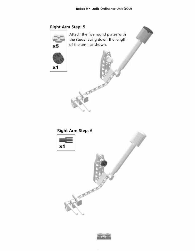
Right Arm Step: 5
Attach the five round plates withthe studs facing down the lengthof the arm, as shown.
Right Arm Step: 6

Robot 9 • Ludic Ordinance Unit (LOU)
208
The GuitarGuitar Step: Complete
Here is what the guitar sub-assembly should look likewhen it is complete.
Guitar Step: 1 Guitar Step: 2
These bricks will attachthe back of the guitar tothe LOU’s body.
Guitar Step: 3 Guitar Step: 4
Guitar Step: 5
Robot 9 • Ludic Ordinance Unit (LOU)
209
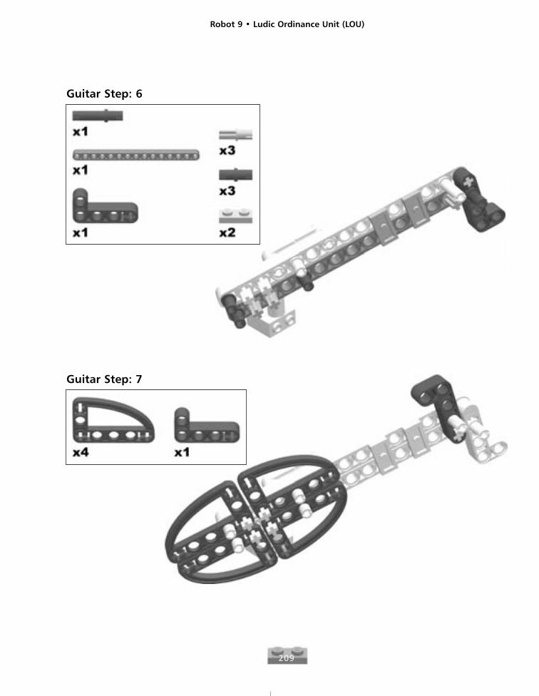
Guitar Step: 6
Guitar Step: 7
Robot 9 • Ludic Ordinance Unit (LOU)
210
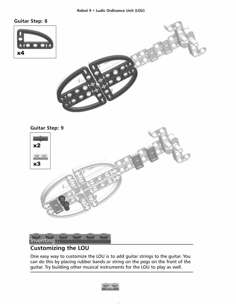
Guitar Step: 8
Guitar Step: 9
Inventing…Customizing the LOUOne easy way to customize the LOU is to add guitar strings to the guitar. Youcan do this by placing rubber bands or string on the pegs on the front of theguitar. Try building other musical instruments for the LOU to play as well.
Robot 9 • Ludic Ordinance Unit (LOU)
211
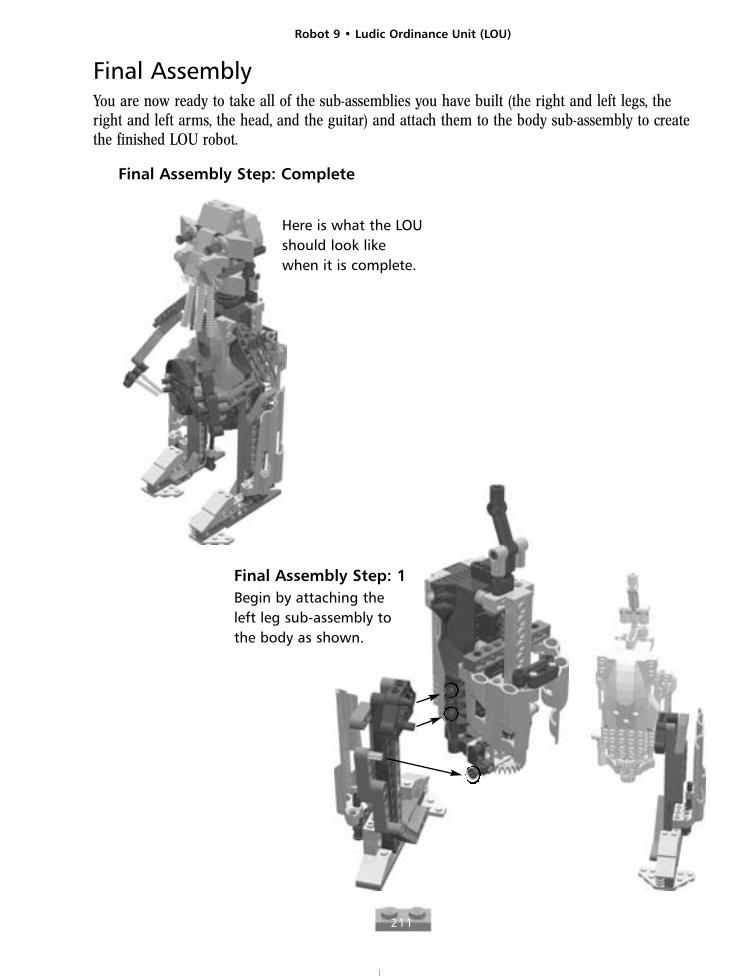
Final AssemblyYou are now ready to take all of the sub-assemblies you have built (the right and left legs, the right and left arms, the head, and the guitar) and attach them to the body sub-assembly to createthe finished LOU robot.
Final Assembly Step: Complete
Here is what the LOUshould look likewhen it is complete.
Final Assembly Step: 1Begin by attaching theleft leg sub-assembly tothe body as shown.
Robot 9 • Ludic Ordinance Unit (LOU)
212
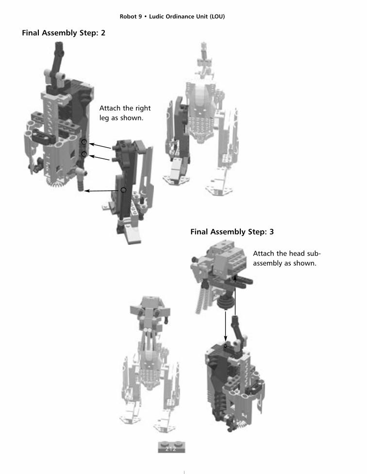
Final Assembly Step: 2
Attach the rightleg as shown.
Final Assembly Step: 3
Attach the head sub-assembly as shown.
Robot 9 • Ludic Ordinance Unit (LOU)
213
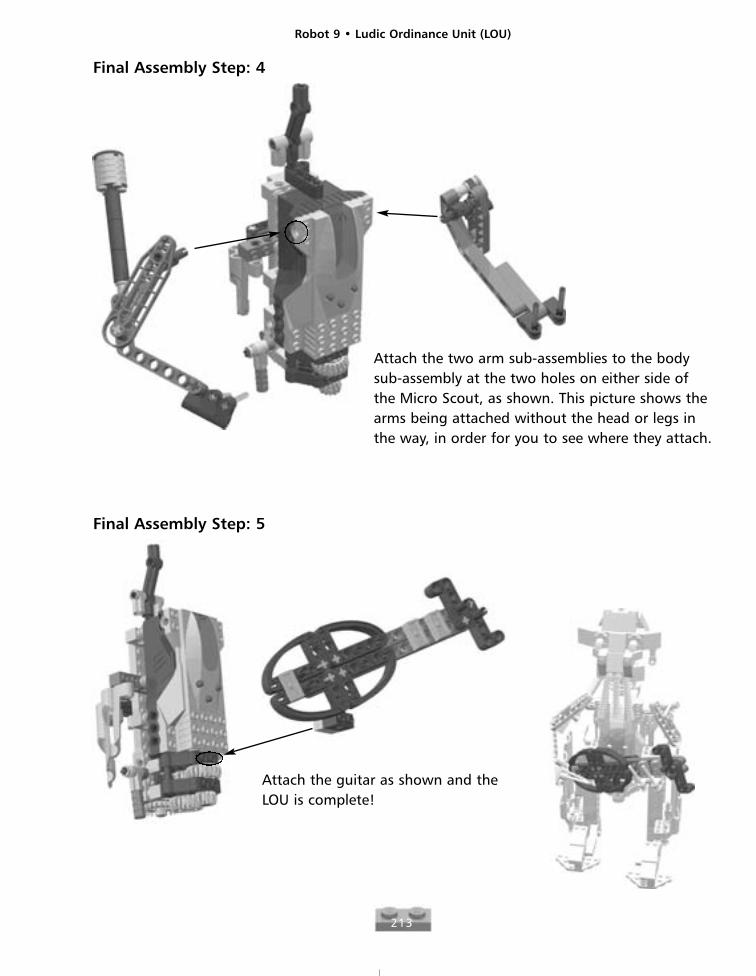
Final Assembly Step: 4
Attach the two arm sub-assemblies to the bodysub-assembly at the two holes on either side ofthe Micro Scout, as shown. This picture shows thearms being attached without the head or legs inthe way, in order for you to see where they attach.
Final Assembly Step: 5
Attach the guitar as shown and theLOU is complete!

Robot 10
215
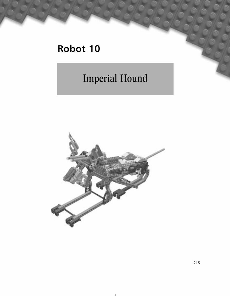
Imperial Hound
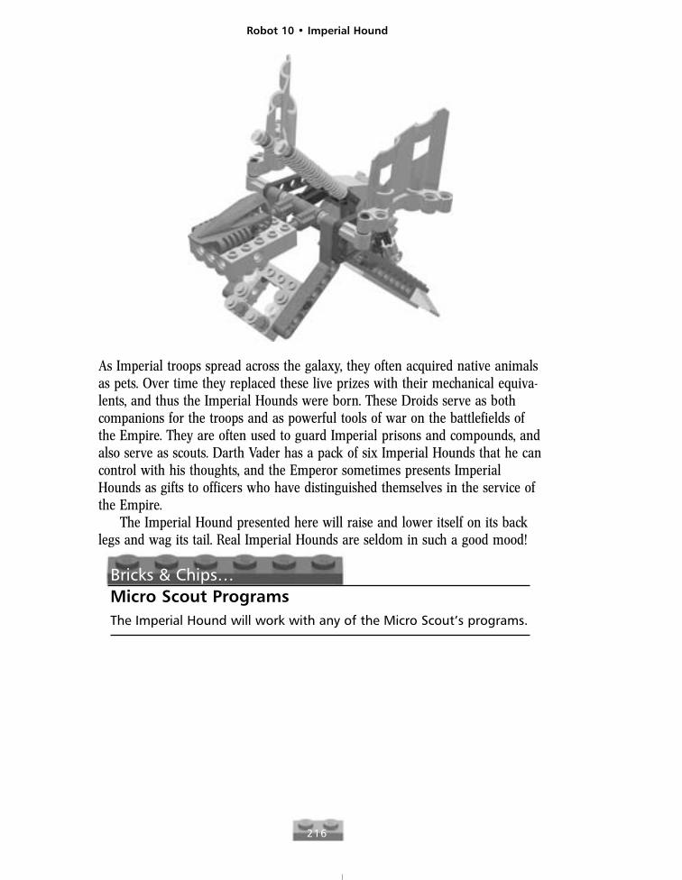
As Imperial troops spread across the galaxy, they often acquired native animalsas pets. Over time they replaced these live prizes with their mechanical equiva-lents, and thus the Imperial Hounds were born. These Droids serve as bothcompanions for the troops and as powerful tools of war on the battlefields ofthe Empire. They are often used to guard Imperial prisons and compounds, andalso serve as scouts. Darth Vader has a pack of six Imperial Hounds that he cancontrol with his thoughts, and the Emperor sometimes presents ImperialHounds as gifts to officers who have distinguished themselves in the service ofthe Empire.
The Imperial Hound presented here will raise and lower itself on its backlegs and wag its tail. Real Imperial Hounds are seldom in such a good mood!
Bricks & Chips…Micro Scout ProgramsThe Imperial Hound will work with any of the Micro Scout’s programs.
Robot 10 • Imperial Hound
216
Robot 10 • Imperial Hound
217
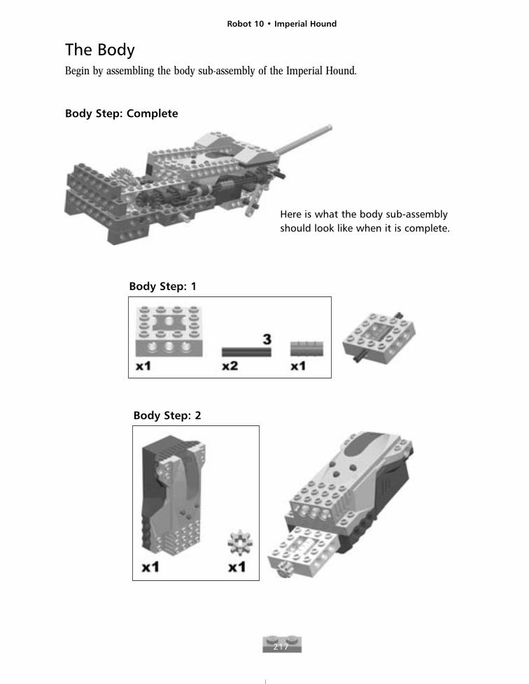
The BodyBegin by assembling the body sub-assembly of the Imperial Hound.
Body Step: Complete
Here is what the body sub-assemblyshould look like when it is complete.
Body Step: 1
Body Step: 2
Robot 10 • Imperial Hound
218
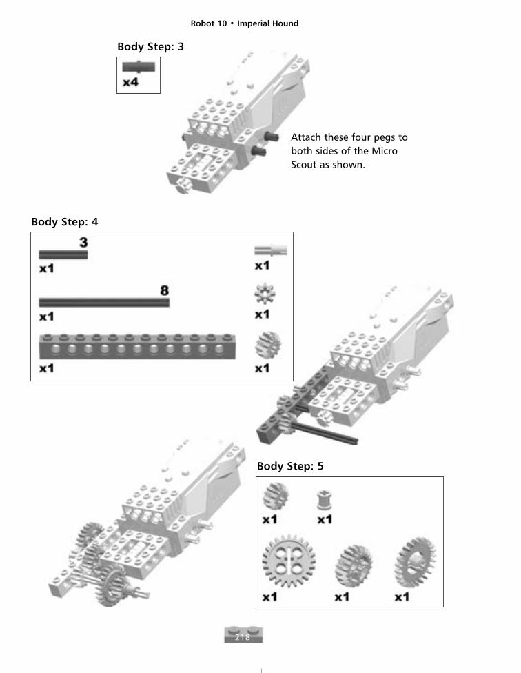
Body Step: 3
Attach these four pegs toboth sides of the MicroScout as shown.
Body Step: 4
Body Step: 5
Robot 10 • Imperial Hound
219
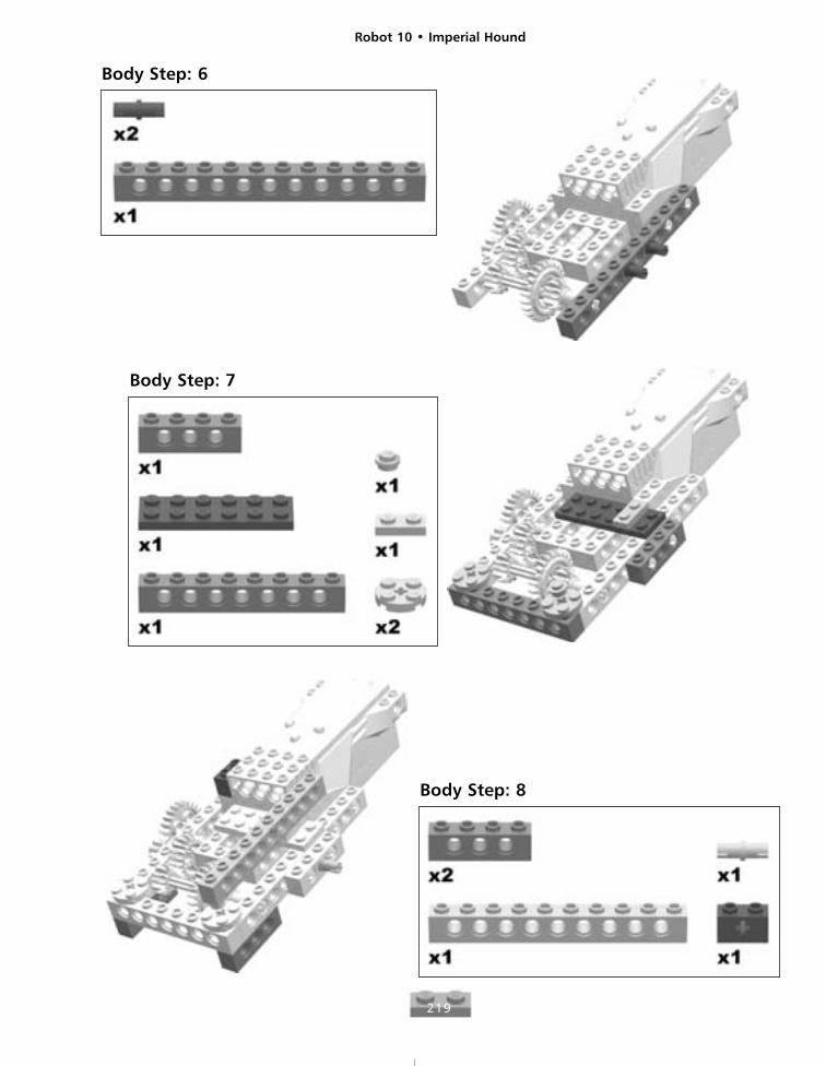
Body Step: 6
Body Step: 7
Body Step: 8

Robot 10 • Imperial Hound
220
Body Step: 9 Body Step: 10
Body Step: 11
Robot 10 • Imperial Hound
221
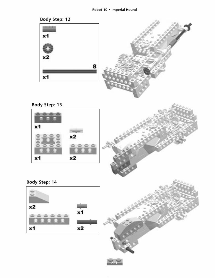
Body Step: 12
Body Step: 13
Body Step: 14
Robot 10 • Imperial Hound
222
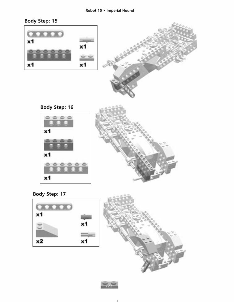
Body Step: 15
Body Step: 16
Body Step: 17
Robot 10 • Imperial Hound
223
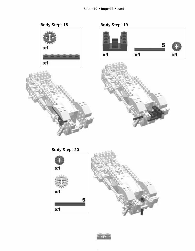
Body Step: 18 Body Step: 19
Body Step: 20
Robot 10 • Imperial Hound
224
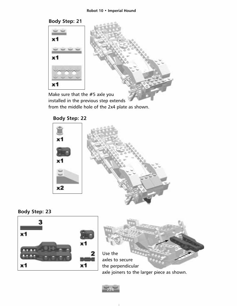
Body Step: 21
Make sure that the #5 axle youinstalled in the previous step extends from the middle hole of the 2x4 plate as shown.
Body Step: 22
Body Step: 23
Use theaxles to securethe perpendicularaxle joiners to the larger piece as shown.
Robot 10 • Imperial Hound
225
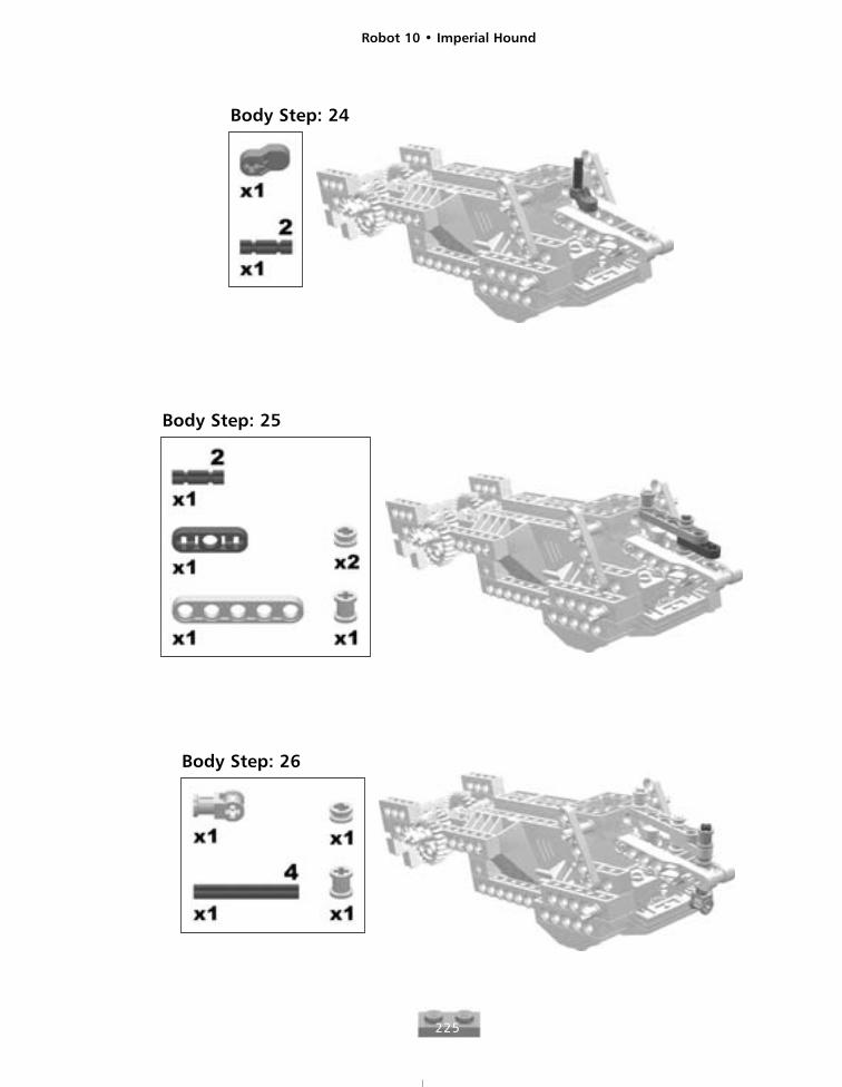
Body Step: 24
Body Step: 25
Body Step: 26
Robot 10 • Imperial Hound
226
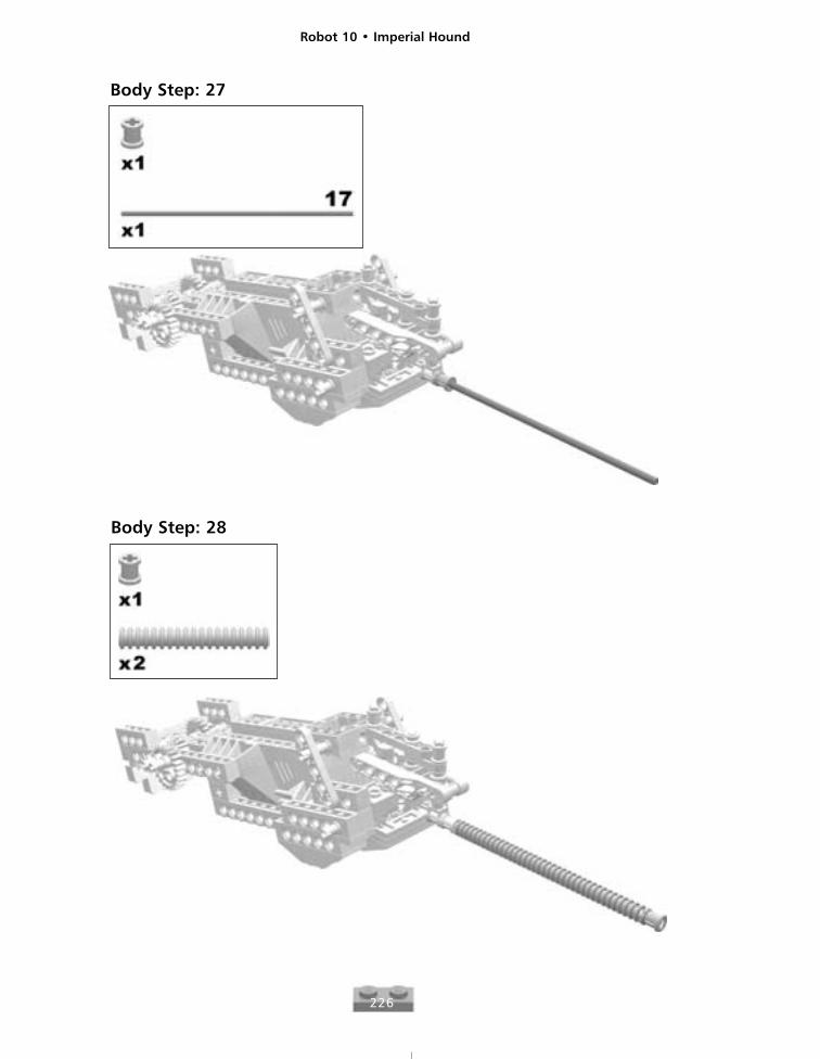
Body Step: 27
Body Step: 28
Robot 10 • Imperial Hound
227
The Head
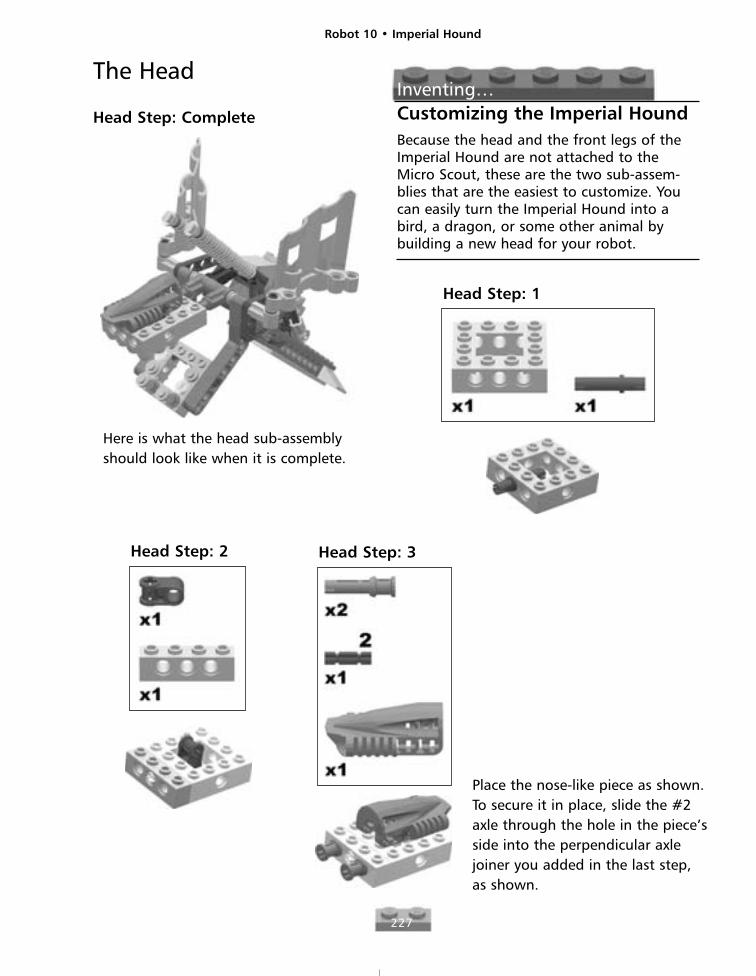
Head Step: Complete
Here is what the head sub-assemblyshould look like when it is complete.
Inventing…Customizing the Imperial HoundBecause the head and the front legs of theImperial Hound are not attached to theMicro Scout, these are the two sub-assem-blies that are the easiest to customize. Youcan easily turn the Imperial Hound into abird, a dragon, or some other animal bybuilding a new head for your robot.
Head Step: 1
Head Step: 2 Head Step: 3
Place the nose-like piece as shown.To secure it in place, slide the #2axle through the hole in the piece’sside into the perpendicular axlejoiner you added in the last step, as shown.
Robot 10 • Imperial Hound
228
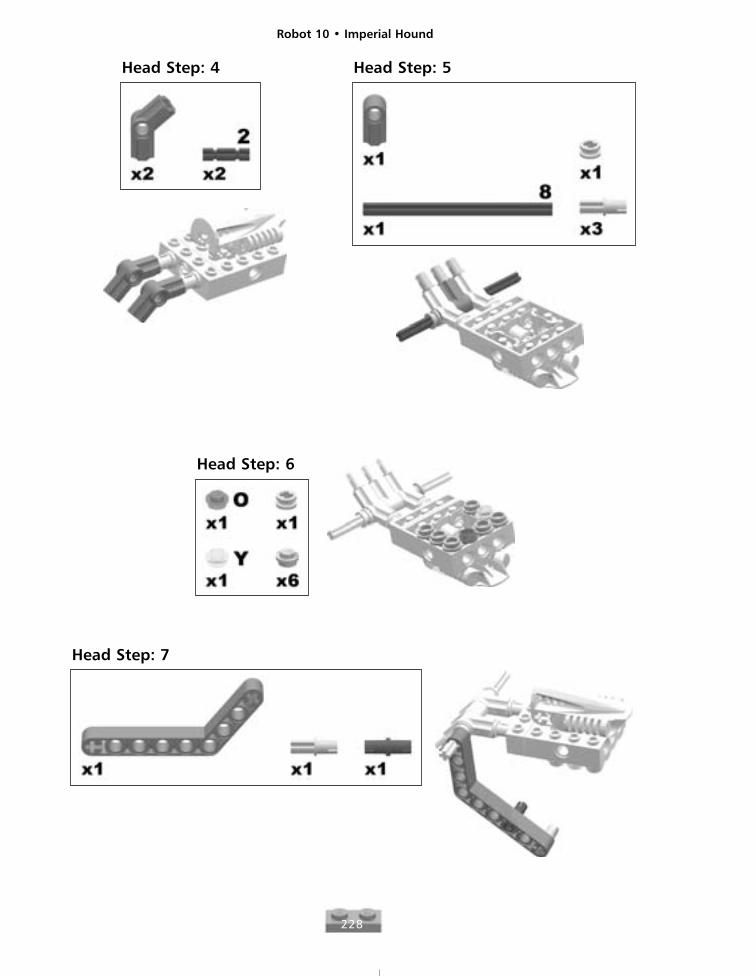
Head Step: 4 Head Step: 5
Head Step: 6
Head Step: 7
Robot 10 • Imperial Hound
229
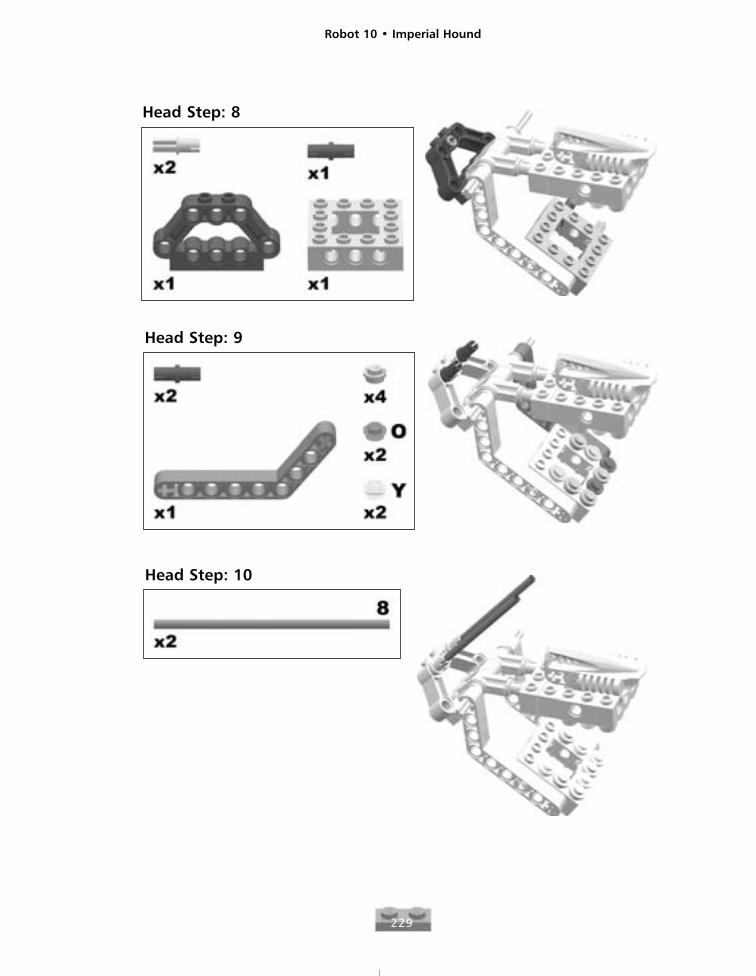
Head Step: 8
Head Step: 9
Head Step: 10
Robot 10 • Imperial Hound
230
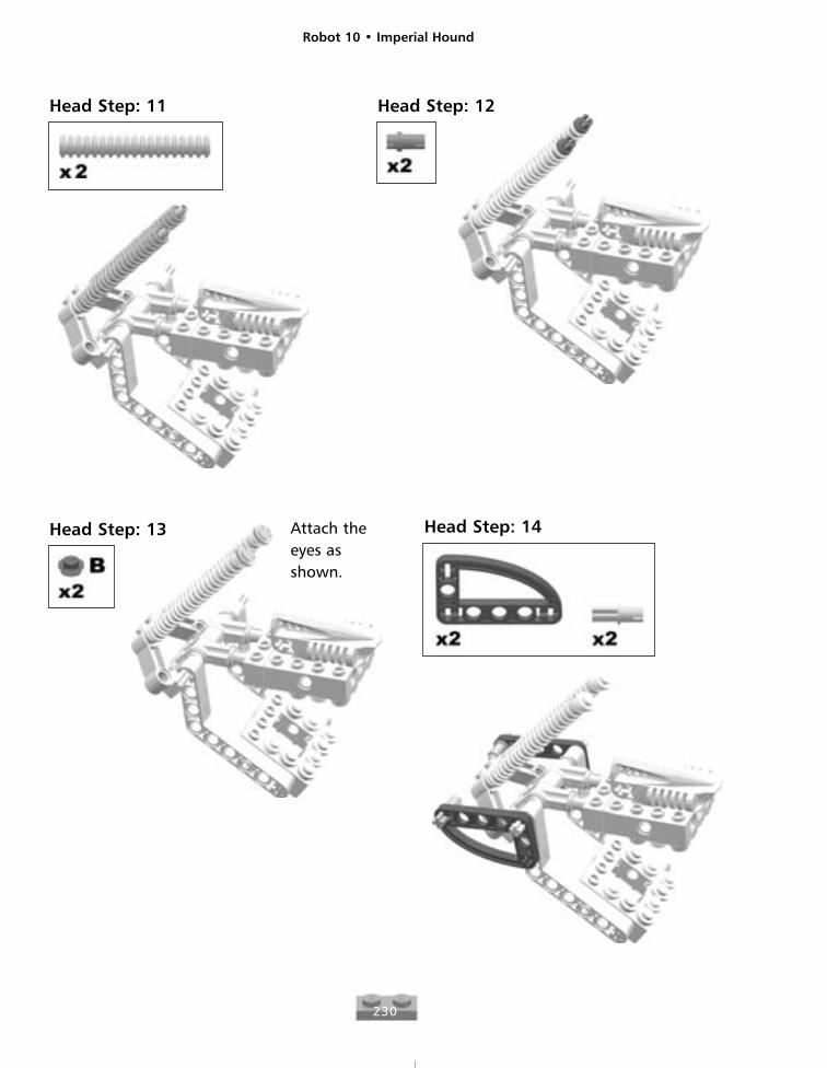
Head Step: 11 Head Step: 12
Head Step: 13 Head Step: 14Attach theeyes asshown.
Robot 10 • Imperial Hound
231
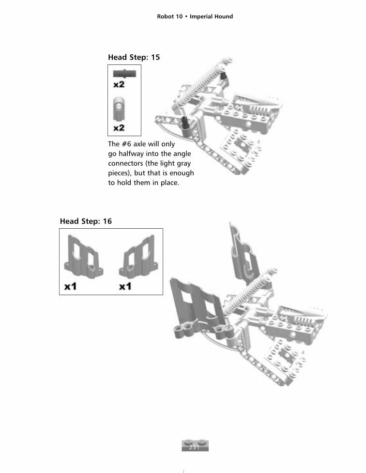
Head Step: 15
The #6 axle will only go halfway into the angleconnectors (the light graypieces), but that is enoughto hold them in place.
Head Step: 16
Robot 10 • Imperial Hound
232
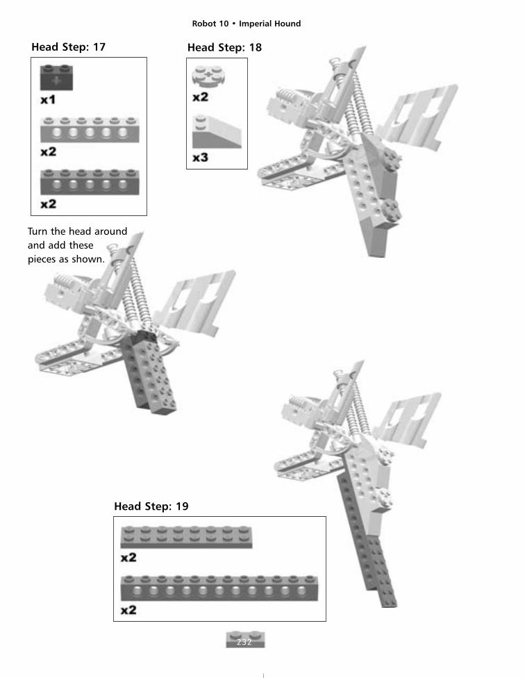
Head Step: 17 Head Step: 18
Turn the head aroundand add these pieces as shown.
Head Step: 19
Robot 10 • Imperial Hound
233
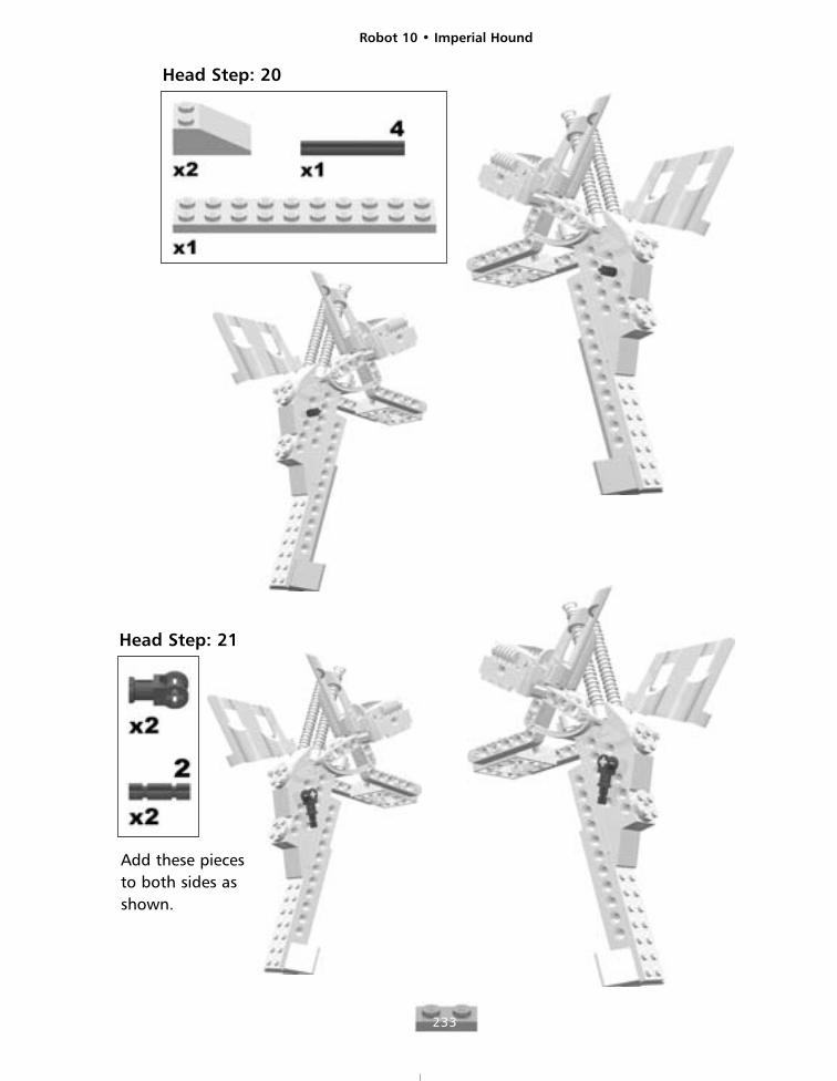
Head Step: 20
Head Step: 21
Add these piecesto both sides asshown.
Robot 10 • Imperial Hound
234
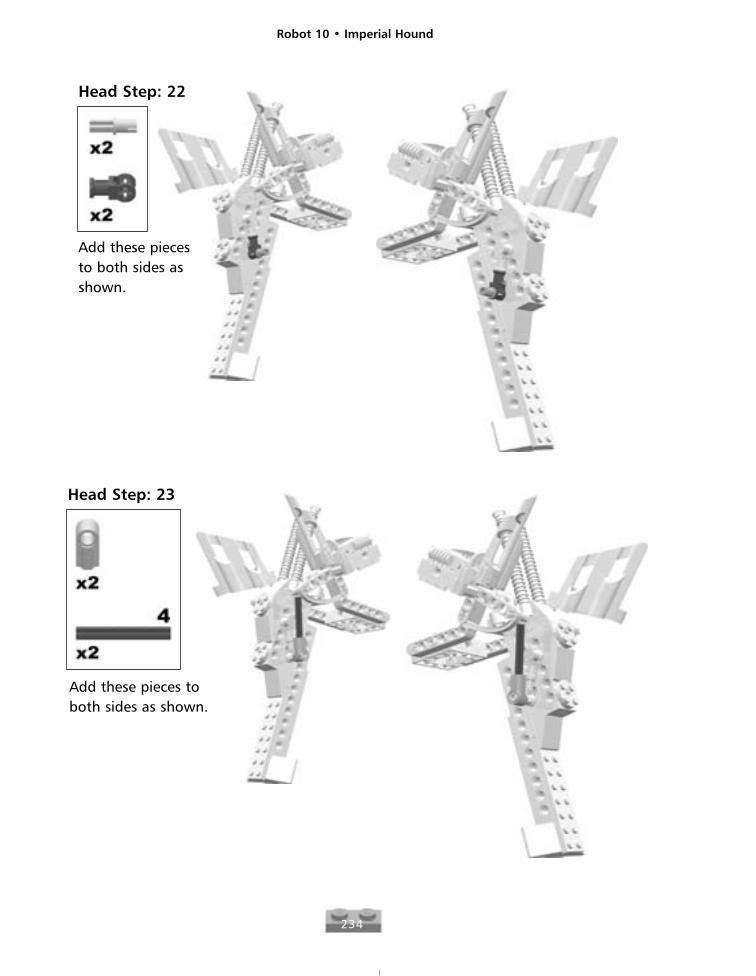
Head Step: 22
Add these piecesto both sides asshown.
Head Step: 23
Add these pieces toboth sides as shown.
Robot 10 • Imperial Hound
235
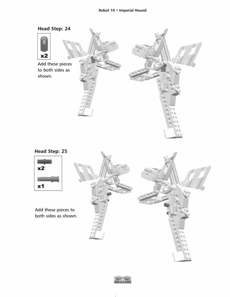
Head Step: 24
Add these piecesto both sides asshown.
Head Step: 25
Add these pieces toboth sides as shown.
Robot 10 • Imperial Hound
236
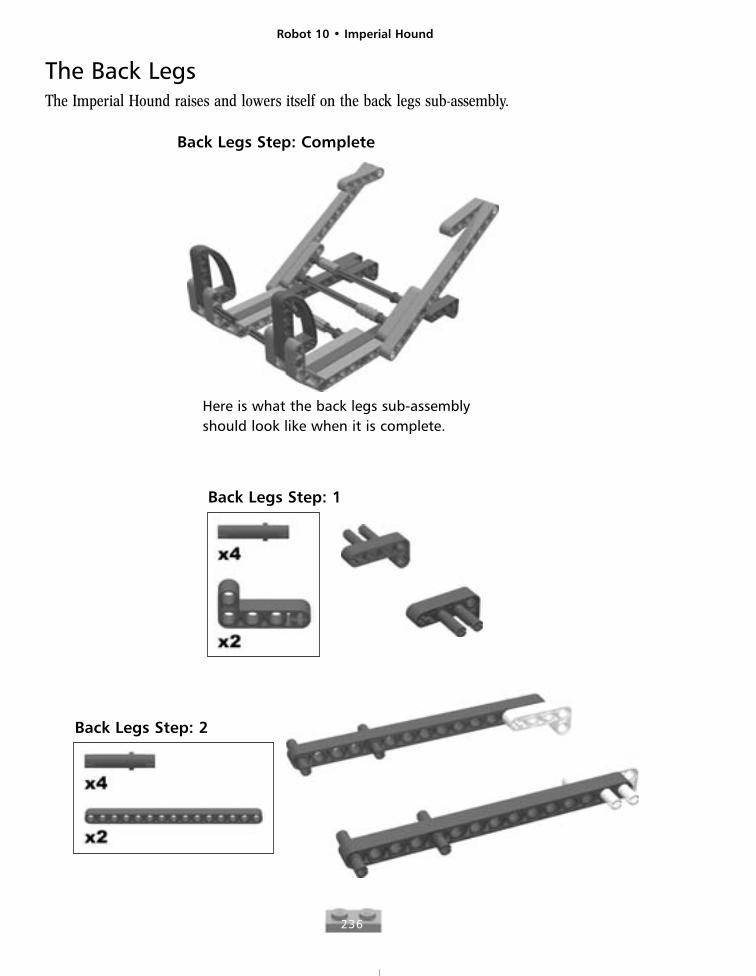
The Back LegsThe Imperial Hound raises and lowers itself on the back legs sub-assembly.
Back Legs Step: Complete
Here is what the back legs sub-assemblyshould look like when it is complete.
Back Legs Step: 1
Back Legs Step: 2

Robot 10 • Imperial Hound
237
Back Legs Step: 3
Back Legs Step: 4
Robot 10 • Imperial Hound
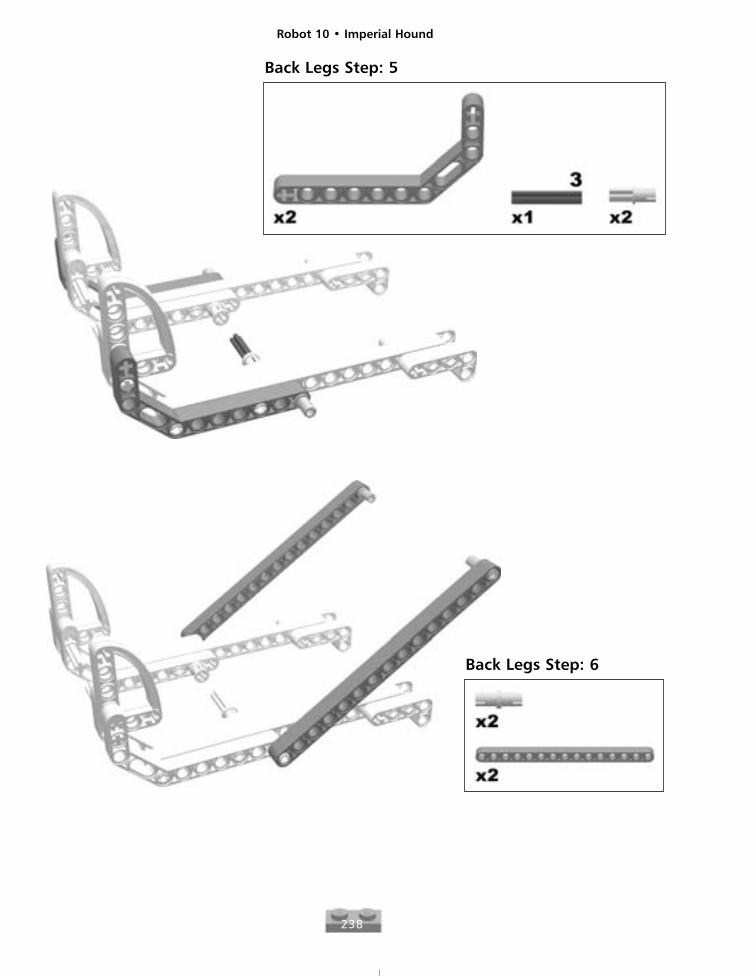
238
Back Legs Step: 5
Back Legs Step: 6
Robot 10 • Imperial Hound
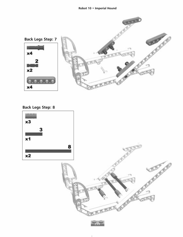
239
Back Legs Step: 7
Back Legs Step: 8
Robot 10 • Imperial Hound
240
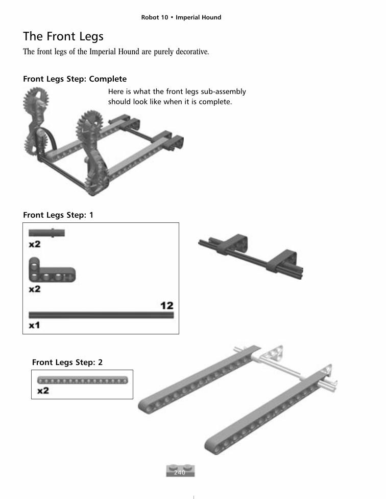
The Front LegsThe front legs of the Imperial Hound are purely decorative.
Front Legs Step: CompleteHere is what the front legs sub-assemblyshould look like when it is complete.
Front Legs Step: 1
Front Legs Step: 2
Robot 10 • Imperial Hound
241
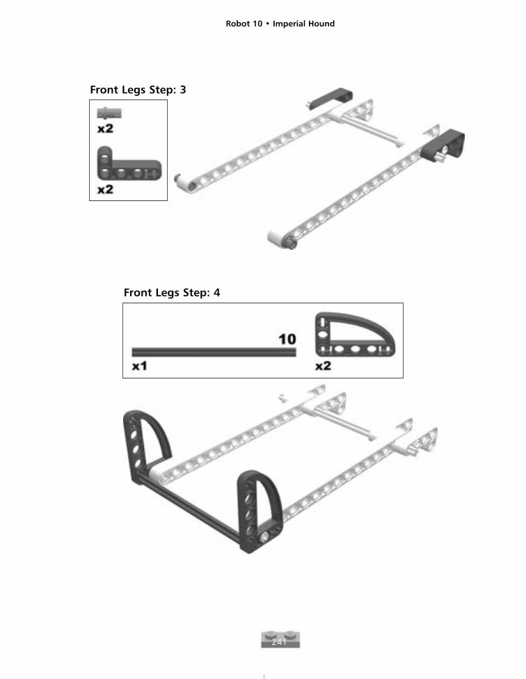
Front Legs Step: 3
Front Legs Step: 4
Robot 10 • Imperial Hound
242
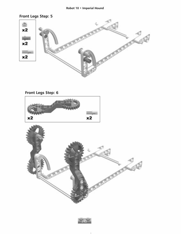
Front Legs Step: 5
Front Legs Step: 6
Robot 10 • Imperial Hound
243
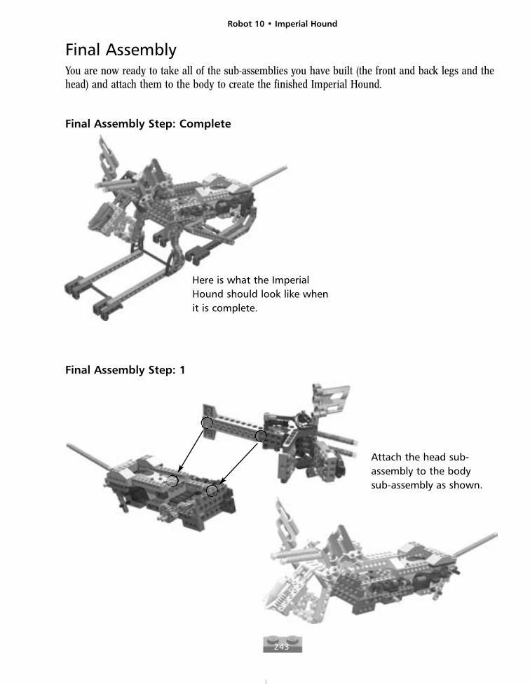
Final AssemblyYou are now ready to take all of the sub-assemblies you have built (the front and back legs and thehead) and attach them to the body to create the finished Imperial Hound.
Final Assembly Step: Complete
Here is what the ImperialHound should look like whenit is complete.
Final Assembly Step: 1
Attach the head sub-assembly to the bodysub-assembly as shown.
Robot 10 • Imperial Hound
244
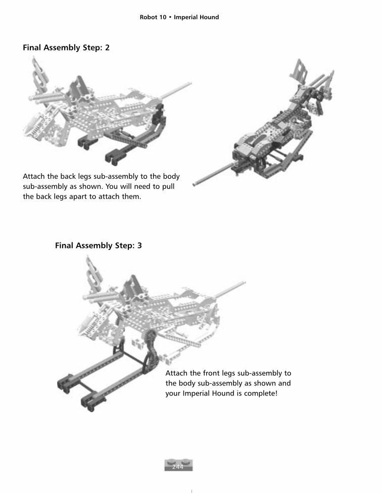
Final Assembly Step: 2
Attach the back legs sub-assembly to the bodysub-assembly as shown. You will need to pullthe back legs apart to attach them.
Final Assembly Step: 3
Attach the front legs sub-assembly tothe body sub-assembly as shown andyour Imperial Hound is complete!