1.0 introduction - memorial university of newfoundlandhawboldt/1sectionsv.pdf · mass/material...
TRANSCRIPT

1.0 Introduction
•
downstream processing refers to the processing of the product from wells, compressor stations and oil batteries
•
purpose is to refine the crude oil or gas to a saleable commodity refineries, upgraders, gas processing plants and petrochemical facilities
•
in this class we will focus on gas processing, refineries/upgraders
•
review of chemistry of petroleum, crude oil and gas

1.1 Hydrocarbons•
petroleum (crude or gas) is made up of various types of HC:
alkanes/paraffins – CnH2n+2 saturated•
C1-C4 are gases at STP, C5-C17 liquids, C18+ wax solids (produce anomalous evaporation, dispersion, emulsification, and flow behaviours)
•
can have n-alkanes (straight chains of HC) or iso-alkanes (branched)
olefins – double bonded HC ethylene CH2=CH2•
unsaturated, more chem. reactive than sats, not usually found in raw gas or crude product of processing
acetylenes – triple bond CH≡CH•
product of combustion rather than natural

•
ring –
naphthenes or cycloalkanes (Cn
H2n
)•
aromatics (arenas)
- compounds that have at
least one benzene ring as part of their chemical structurenonhydrocarbons
influence product qualityS – 0.65-6% by wt free S, H2S (in gas 50%), mercaptans(C2H2SH), thiols ((C2H5)2S), thoiophenes, low API contain moreN – 0.1-2%, reduces heat value, pyridines, quinolenes, indoles, largely unid’ed in crudeoxygen – free O2/CO2, alcohols, esters, phenols, fatty acids, decompose to naphthenic acids on distillCO2 – common gases/cond, corrosive probs (carbonic acid), dehyd important to prevent corrosionVd, Ni, Cu, Zn, Fe

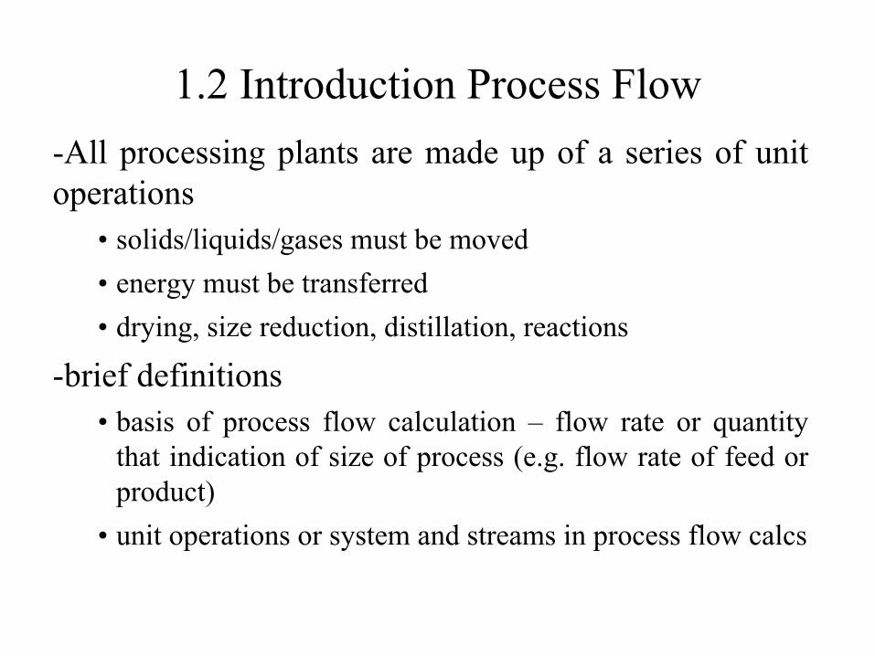
1.2 Introduction Process Flow-All processing plants are made up of a series of unit operations
•
solids/liquids/gases must be moved•
energy must be transferred
•
drying, size reduction, distillation, reactions
-brief definitions•
basis of process flow calculation –
flow rate or quantity
that indication of size of process (e.g. flow rate of feed or product)
•
unit operations or system and streams in process flow calcs

Mixer Reactor
Splitter
SeparatorMixer
unit operation
collection of unit ops

Series of unit operations where process variables are specified:
Specifications –
stream specs and system specs (conversions etc…)Mass fractions –
xA
= mass of A/total mass of systemMole fractions –
yA
= moles of A/total moles in system
1.2.1 Process Flow Diagram
Mixer
100 moles/h C2
H6T=320oCP=1.4 bar
2000 moles/h air0.21 O2
0.79 N2T=320oCP=1.4 bar
0.0476 C2
H60.2 O20.752 N22100 moles/h

e.g. A gas mixture has following composition by mass:N2
= 0.03CH4
= 0.85C2
H6
= 0.08C3
H8
= 0.03CO2
= 0.01Calculate molar composition

1.2.2 Degree of Freedom (DOF) AnalysisDOF = independent variables –
independent equationsDOF = 0 problem completely specifiedDOF < 0 over specified, some of equations are either redundant or inconsistentDOF > 0 underspecified, need some more equations
Equation sources:
•
mass/material balances -
for nonreactive process no more than ni
material balance equations may be written where “i”
is number of species•
energy balance•
process specifications –
how several process variables are related (e.g. percent recovery or degree of conversion)
•
Physical properties and laws –
equations of state or other equilibrium relations•
Physical constraints –
for example mass fractions must add up to 1•
Stoichiometric reactions

1.2.3 Material Balancesdmi
/dt = mi,in – mAiout ±
rirate accumulation of “i”
= rate in of “i”
–
rate out of “i”
±
rate of
consumption of “i”where ri
–
rate of consumption or production of “i”-
form of ri
depends on reaction, in general:ri
= k Πi=0n
Cix
where Ci
-
is concentration or partial pressure of species “i”k –
is rate constant = Ae-Ea/RT
e.g. global reaction is as follows: CH4 + 2O2 CO2 + 2H2O (irreversible reaction at 800oC and 1 atm)So reaction rate may be = rCH4 = k PCH4 PO2
2
H2 S H2 + ½ S2
So reaction rate may be = rH2S = kf PH2S - kr PH2 PS21/2

a.) Application to reactors
Design variables:T and P – optimal to max conversion and minimize by-productsV – determines time for reaction(s), also important from cost, weight, space constraints
1. Residence time –
time component stays in reactor = volume of vessel/flow rate

2.
Type reactor –
batch, semi-batch, or flow/continuousdetermines form of mass balance equationA B + Cstart with mass balance on component “A”: dmA
/dt = mA,in – mAiout ±
ri
i.
Batch –
reactor charged with reactants, allowed to react, then products/unreacted material withdrawn, no flow in or out so
t= 0 to reaction time
•
So dmA
/dt = ±
rA
(in reactors usually use mole balance so ni
)
ii.
Continuous Flow Reactora)
CSTRnA 0 = nAi,in – nAiout ±
rA

b.
PFR –
fluid flows as a “plug”
nAdnA
0=
nA |V
– (nA +dnA )|V+dV ±
rA0 = dnA /dV ±
rA
3.
Mixing Pattern 4.
Feed Composition
5.
Catalyst –
speeds up rate of reaction can be liquid (e.g. acid/base), solid (metal based), biological (enzymes)
•
not consumed in reaction •
act by decreasing the energy required for reaction (Ea
)

energy
reaction extent
E3
E2
E1
before catalyst Ea
=E3
-E1
after catalyst Ea =E2 -E1
reactants products

b.) Chemical Equilibrium•
when no changes can occur without outside stimulus –
thermodynamic eqm (absence of change thermo properties or tendency to change), chemical equilibrium
•
chemical kinetics tell us the rate of reaction while chemical equilibrium tells us if reaction will occur at specified T and P
and
the final equilibrium concentrations (much the same way that thermodynamics tells us direction and quality of energy while heat transfer refers to the rate of energy transfer)
•
irreversible reaction (reactants products) where equilibrium composition refers to complete consumption of limiting reactant OR
•
reversible reactions (reactants products) where the direction of reaction can shift according to concentration of reactants/products, T and/or P
conversion = (species input –
species output)/species input
Thermophysical properties•
use correlations (Equations of State, excess Gibbs) to determine behaviour of gases/liquids/solids
•
P, T, V, and/or n determine the “state”
of substance
•
ideal gas law and more complex EOS (PR, RK, VdW, compressibility factor), Wilson, UNIQUAC

c.) combustion reactions•
rapid reaction of fuel with oxygene.g. 1
CH4
+ 2O2 2 H2O + 1CO2
1
C8
H17
S+ 35/2O2 17/2 H2O + 8 CO2 + 1 SO2
•
since O2
source is usually air (21% O2
and 79% N2
) have to account for N2 content
if need 1 mole O2 1/0.21 need 4.76 moles air so for CH4 example need 9.5 moles of air (stoichiometric air)
•
as impurities increase so does O2
demand, also H2
O content in fuel or air increases then more O2
must be added (as temperature increases H2
O content of air)stoichiometric air –
amount of air required to convert all of fuel to CO2
, H2
O, SO2 but to account for impurities in air and water often use excess air
•
Usually complete combustion is not possible:C8
H17
S+ nO2 H2O + CO2 + SO2 + CO + SO etc…

•
the value of fossil fuel as a heating medium is determined by heating value of gas or amount of heat released during
combustionHV –
amount of heat released during complete combustion w/
stoichiometric airHV=Σxi
HiHHV -
amount of heat released during complete combustion w/
stoichiometric air if include latent heat of vaporization of H2
O or if H2
O in stream is condensed Fuel + O2 CO2(g)+H2O(l)
LHV -
amount of heat released during complete combustion w/ stoichiometric air if H2O in steam is NOT condensed
Fuel + O2 CO2(g)+H2O(g)HHV=LHV+nH2O
ΔHH2Ovap(Tref)
•
usually reference temperature is 15C which why latent heat not included in LHV

d.) Phase EquilibriumMost chem. processes material is transferred from one phase to anotherSingle component phase diagram:
P
T

Multi-component phase diagramMixture of natural gas
0
2000
4000
6000
8000
10000
-160 -110 -60 -10 40
Temperature (C)
Pre
ssur
e (k
Pa)

Phase Diagram with multiple liquid phases
L1
and L2
v
v+L2v+L1
L1 L2
T
x,y0 1

T-xy methanol phase diagram for water-methanol mixture
335
340
345
350
355
360
365
370
375
0 0.5 1
mole fraction of methanol
T (K
)
liquid molefraction
vapour molefraction

1.2.4 Energy Balance•
Flow system
Q-
W + Fi
Hi
– Fo
Ho
±
ΔHR
VrA
= dE/dt (neglecting KE and PE) kJ/s
•
in a pipe where no accumulation term and possibly KE and PE:
Qo
–
Ŵs
+ mo
((ui2- uo
2)/2 + g(zi
-zo
)+ (hi
-ho
)) = 0 kJ/ s orQ-Ws
+ m((ui2- uo
2)/2 + g(zi
-zo
)+ (hi
-ho
)) = 0 kJ/•
get Bernoulli eqn if substitute ho
-hi
= Δh -
Δ(Pv) = Q-W•
and W = PΔv –
lw (friction loss)
Δh –
vΔP -
PΔv = Q-PΔv + lwΔh = Q + vΔP + lwWs
+ (uo2- ui
2)/2+g(zo
-zi
) + vΔP + lw = 0v = 1/ρWs
+ (uo2- ui
2)/2+g(zo
-zi
) + ∫P/ρ
+ lw = 0

•
Typically in process flow calcs perform material balances followed by energy (as they are coupled)
•
Terms used in energy calcs:Heat of reaction – ΔHr - enthalpy change when stoichiometric quantities of reactants at T and P are completely converted to products at same T and P
ΔHr < 0 reaction is exothermic e.g most fossil fuel combustionΔHr > 0 reaction endothermic e.g. most fossil fuel
pyrolysis
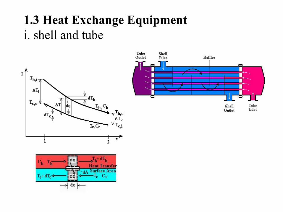
1.3 Heat Exchange Equipmenti. shell and tube

ii. Condensers•
heat transfer equip used to liquefy vapours where latent heat of
vap us absorbed w/ coolant
iii. Reboiler •
usually shell/tube ex used to boil liquid for recirculation
www.distillationgroup.com

iv. Cooling Towers•
used to lower temp of recirc water used in condensers and heat exchangers•
large diameter columns with special packing to give good contact
with low P drop
•
water distributed thru tower via nozzles or troughs of pies and air passed thru forced draft and induced draft fans
Closed Loop Cooling Tower System (www.cheresources.com)

1.4 Mass transfer Ops•
mass transfer processes can be modelled by diffusion rate processes (gas absorption, l-l extraction, packed towers) and/or equilibrium stages (distillation, leaching, extraction in distillation towers, diffusion batteries)
•
regardless of model need to know equilibrium relationship between phases and components because once 2 phases are in equilibrium there is
no mass transfer
•
as said before equilibrium is set by T, P, n so use phase rule:
F=C-P+2 determines degree of freedom for phase calcs
a)Eqm relationship•
in our applications focus on distillation columns which are series of eqm stages•
where two streams run counter-currently to each other, in each stage they are brought into contact, mixed, and separated, to work must enter stage not in eqm and leave very close to eqm
•
distillation or fractionation is a method of separation of HC by
relative volatilityαij
=Ki
/Kjwhere K-
K-values = yi
/xi
really a measure of separation between liquid (x) and gas (y) fractions at a give T and P

i.
fractionators •
are designed as a series of equilibrium flashes:equilibrium flash –
say have a pure component of vapour and liquid at specified T and P, at equilibrium a certain fraction exists as vapour the rest as liquid, if change temp and/or pressure and allow to equilibrate fractions will shift, if now add other compounds to pure and allow to equilibrate the l and v fractions
and composition will again shift how shift determined by thermo f(comp, T, P)
TSPS
Tin
, Pin
, z1
v, y1
l, x1
Tin
TS
x1 y1

in series of flashes:vapour enters from stage below @ T1l enters from stage above @ T2 (T1>T2)heat and mass transfer occurs so exit streams from stage @ bubble pt l and dew pt v at same T and P
contact T
xBP yDP
dew pt v
bubble pt l T1
T2
l at T2
v at T1
composition of exit streams are related by equilibrium constant (K)Ki
= ydp
/xbp
where K=f(T,P) –
calculate using thermodynamics (del G or chem potential)
Stage may be a tray or part of packing (discussed in detail later)

Condenser –
may have total or partial reflux
Reflux
RectifyingSection –
v enriched w/ low boilers
Stripping section –
l enriched w/ high boilers
ReboilerBottom Product
Overhead
Figure modified from Perry’s

Bubble
Sieve
Valve
•
May have multiple feeds at low T as approach top to provide reflux•
Use top l feed w/ crude stabilizers and deethanizers
purpose is usually meet specs for bottom product , OH composition determined by upstream process units
•
trayed 1. bubble cap –
prevents l from weeping thru vapour passages-
turndown ratio 8:1-10:12.
valve –
lower cost3.
sieve or Perforated –
lowest cost, high capacity but subject to weeping•
initial design calcs based in theoretical trays (eqm calcs) and
then apply a tray efficiency


•
packed columnsas opposed to tray columns, contact btw l and v maintained
throughout column (vs. specific pts) more detail later
•
number of trays function of separation factors
Typical McCabe-Thiele diagram for distillation of a binary feed (Perry’s)
numbers 1-6 represent theoretical amount of trays required to achieve separation never truly reach eqm at trays therefore apply “tray efficiency”
where Hv
is the enthalpy of the feed at the dew point, HF
is the enthalpy of the feed at the boiling point, and HL
is the enthalpy of the feed at its entrance condition
Lv
Fv
HHHH
q−−
=

•
condenser –
partially or totally condense the vapour to a boiling liquid to return to column and enhance mass transfer as it is transferred to rising vapour stream called reflux (increases purity of OH product)
•
reboiler –
liquid partially reboiled
to vapour
temperature increases as move down column due increase in pressure and concentration of higher boiling components
in design mass and energy balances are done at each stage or plate to determine final concentration, T and P profiles.
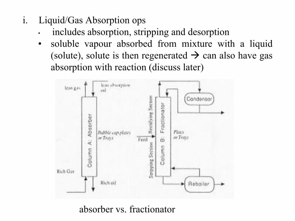
i.
Liquid/Gas Absorption ops•
includes absorption, stripping and desorption•
soluble vapour absorbed from mixture with a liquid (solute), solute is then regenerated can also have gas absorption with reaction (discuss later)
absorber vs. fractionator
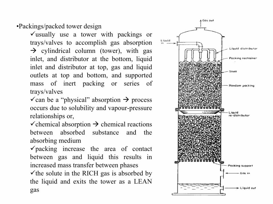
•Packings/packed tower designusually use a tower with packings or
trays/valves to accomplish gas absorption cylindrical column (tower), with gas
inlet, and distributor at the bottom, liquid inlet and distributor at top, gas and liquid outlets at top and bottom, and supported mass of inert packing or series of trays/valves
can be a “physical” absorption process occurs due to solubility and vapour-pressure relationships or,
chemical absorption chemical reactions between absorbed substance and the absorbing medium
packing increase the area of contact between gas and liquid this results in increased mass transfer between phases
the solute in the RICH gas is absorbed by the liquid and exits the tower as a LEAN gas

3 types of packing:1. dumped or random packing –
units 6-75 mm in diameter, cheap
inert material (clay, porcelain, plastics) -
area/volume column = 65-625 m2/m3
2.
stacked –
50-200 mm in size, not commonly used due to channelling
3.
structured –
knitted type mesh packing (i.e. wire gauze)-
high l loading possible
-
area/volume column = 200-250 m2/m3
stacked structured random
http://www.tower-packing.com/Dir_structured_packing.htm

•
initial design calcs based on P drop and diameter (Eckert method)•
must minimize P drop across column (low gas mass velocity) which
also prevents flooding (high l or v rates when delPgas
> net gravity head of l) but if gas mass velocity too low then must have larger column to maximize contact between l and v
e.g. del Pmax=5-15 mm H2O/ft packed depth (max of 25) or del Pflood
= 0.115Fp0.7
where Fp
is packing factor (dimensionless, del P in H2O/ft pack)
flooding
max delPrectifying
stripping
operating range
(l/v)max
liquid flowrate
min allowable effchanneling
vapour flowrate

•
other column problems that must be mitigated by operating properly:foaming entrainmentweeping (when trays rely on gas pressure to hold l start leaking l thru gas
orifices)•
the maximum amount of solute that can be absorbed by the liquid is defined by equilibrium calcs, actual amount is less and called the operating line:
y
x
Equilibrium line
Operating line -
stripping
Operating line -
absorption
Tower top
Tower bottom
** reversed op and eqm line for distillation
•
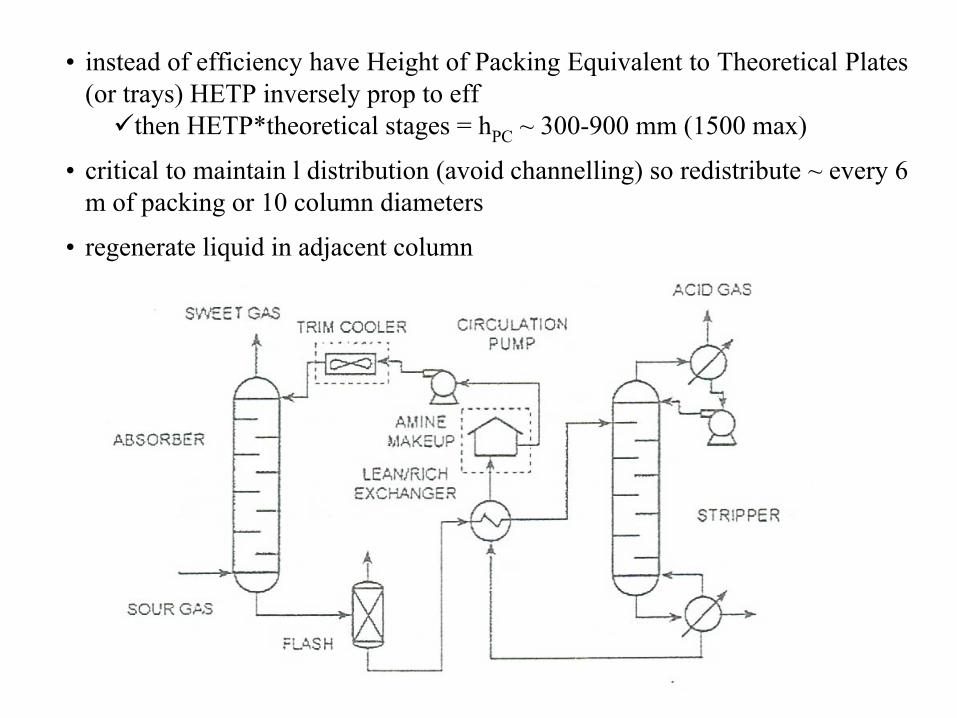
instead of efficiency have Height of Packing Equivalent to Theoretical Plates (or trays) HETP inversely prop to eff
then HETP*theoretical stages = hPC ~ 300-900 mm (1500 max)
•
critical to maintain l distribution (avoid channelling) so redistribute ~ every 6 m of packing or 10 column diameters
•
regenerate liquid in adjacent column

iii.) solid/gas absorption or fixed bed absorbers and fluidized beds•
solid acts as absorbent to remove impurities•
as with gas-liquid contactors can have physical or chemical absorption•
adsorbent particles placed in bed 0.3-1.2 m deep supported on screen or perf plate, feed gas flows down thru bed to prevent fluidization, usually have 2nd
bed regenerating
•
fluidized beds solid particles are fluidized to enhance mass and
heat transfer