10 myths of cfd
TRANSCRIPT
M e c h a n i c a l a n a l y s i s Wh
it
eP
aP
er
w w w . m e n t o r . c o m
The 10 MyThs of coMpuTaTional fluid dynaMics
drs. ivo Weinhold & John parry, MenTor Graphics, Mechanical analysis division

The 10 Myths of computational fluid dynamics
w w w. m ento r.co m /m e chanic al2 [9]
How tHe 5 MytHs of CfD Have evolveD to beCoMe 10
inTroducTion
Some five years ago we felt compelled to write our whitepaper “The Five Myths of Computational Fluid Dynamics” [1]. Since then, we have had quite a lot of feedback regarding our views, and broadly, our debunking of these myths resonated with people. Through all the feedback and conversations we’ve had on this topic, it’s become clear that the situation is more complex than we first thought. After spending some time to cogitate on this, we felt compelled to write an addendum to “The Five Myths…”. Here, we provide a summary of the original myths, introduce four new related myths, and add a completely new one.
Summarizing “The 5 myThS of CompuTaTional fluid dynamiCS”
Since we wrote the “The Five Myths…” quite a lot has happened in the CFD market, so before summarizing these myths we should clarify the scope of this whitepaper. Our comments relate specifically to the broadest section of the CFD market, that of commercial general-purpose CFD software solving the Navier-Stokes equations. We are deliberately excluding so-called meshless approaches using Lattice-Boltzmann methods, and application-specific CFD such as tools for injection moulding, electronics cooling, data center simulation, etc. where their tailored functionality delivers a different value proposition to customers. So, to recap:
MyTh #1: cfd is Too difficulT To be used in The desiGn process
This myth has a historical basis. Like FEA codes in the distant past, CFD codes of the 1980s and 1990s were difficult to use. Fit-for-purpose meshing, choice of solution numerics, turbulence modeling, achieving and judging solution convergence, assuring result fidelity, and correct result interpretation were all once expert-only activities. Today, the skills a mechanical designer needs to operate the CFD software are simply knowledge of the CAD system and the physics pertaining to the product, both of which the majority of design engineers already possess.
figure 1: Cad-embedded Cfd package floefd for Siemens nX

The 10 Myths of computational fluid dynamics
w w w. m ento r.co m /m e chanic al3 [9]
This is because the automation and overall usability of the tools has increased so much [2]. However, the importance of usability is largely misunderstood; and in this, we have discovered a new myth: Myth #6 – Usability is not a prerequisite for a reliable and reproducible workflow.
MyTh #2: cfd Takes Too lonG To use durinG The desiGn process
The greatest time sink for CFD has always been the meshing process, with a considerable amount of manual intervention needed to achieve acceptable mesh quality by eliminating gaps and overlaps, reducing skewness, aspect ratio, warpage, and controlling the volume of individual cells (cell size ratio to neighbor cells, smallest cell size, and mesh distribution). As design inherently involves changing geometry, this semi-manual process had to be repeated for each design iteration. All of these steps can now be fully automated using native 3D CAD data directly for fluid flow simulations without the need for translations or copies. New parts and features resulting from design changes can be meshed in a matter of minutes, dramatically reducing the time required for analysis.
Acceptance of this has, however, revealed another myth: Myth #7 – Accuracy has to be sacrificed to use CFD during the design process.
MyTh #3: cfd is Too expensive To be used by Mechanical desiGners
In our original whitepaper, we observed that traditional CFD codes cost in the region of $25,000 to lease for one year. The latest generation of CFD code intended for use during the mainstream design process cost around $25,000 for a perpetual license. The only ongoing cost is a maintenance fee on the order of 18% ($4,500) per year. The cost of ownership is further reduced because it can be used by a mechanical design engineer with minimal training1. Novel techniques, such as immersed boundary treatments for fluid–solid surface friction and heat transfer, massively reduce the mesh count required to achieve accurate results, allowing useful work to be undertaken on multicore personal computers and laptops, reducing the cost still further.
figure 2: efficient thermal simulation of an electronics enclosure
1 That is training in the use of the tool. Knowledge of fluid flow and heat transfer appropriate to the application is necessary, but not a detailed knowledge of Cfd.

The 10 Myths of computational fluid dynamics
w w w. m ento r.co m /m e chanic al4 [9]
This myth proved relatively uncontroversial; however, it relates to a third new myth: Myth #8 - Experts are needed to get accurate CFD simulation results.
MyTh #4: you can’T direcTly use your cad Model To do cfd analysis
In the past, it was necessary to copy or translate the CAD model to a different program and then modify it substantially to create the CFD model. Many people found it more reliable and less effort to start from scratch by recreating the geometry within the CFD program, despite this involving a considerable expenditure of time and introducing an additional and significant source of error.
figure 3: Cost-effective Cfd - Simulation of an automotive turbo charger
figure 4: direct use of native Cad geometry for Cfd simulations

The 10 Myths of computational fluid dynamics
w w w. m ento r.co m /m e chanic al5 [9]
Today, native 3D CAD data can be used directly for flow simulations without the need for translations or copies, or creating phantom “objects” in the feature tree to represent the flow spaces. The myth that CAD geometry can’t be used directly for analysis persists today, but in a slightly different guise, giving us our fourth new myth: Myth #9 - Production CAD is too complex to use for analysis.
MyTh #5: MosT producTs don’T need cfd analysis
We judge this myth to have been largely consigned to history. It is apparent that, today, CFD is used to improve products as diverse as swimming pools, toilets, hand dryers, lawn sprinklers, gas meters, production printing systems, disk drives, and oil filters to name just a few applications. Although not yet complete, the democratization of CFD for use in product design has extended into undergraduate courses and even to high school programs [3, 4].
At this point, we would like to introduce the new, or at least newly identified, myths of CFD that have come to our attention.
inTroduCing five new myThS of CompuTaTional fluid dynamiCS
MyTh #6: usabiliTy is noT a prerequisiTe for a reliable and reproducible WorkfloW
We were perhaps remiss in not covering this last time. However, its resilience and the passage of time have made this myth clearer. Indeed, there seems to be a school of thought that CFD should be (perhaps reassuringly) difficult to use.
A high level of usability reduces the mental effort needed to drive the tool, leading to less mistakes, smoother workflows, higher efficiency, greater motivation and engagement, and happier designers and engineers. Usability does not hinder experts, but supports both experts and non-experts, making quality and reliability less dependent on individual performance.
Usability is a prerequisite for reliable, reproducible high-quality CFD results because mistakes can arise from a number of sources and are easy to make. Mistakes are almost inevitable when the engineer is required to perform hundreds, if not thousands, of separate operations required to build a CFD model from first principles, starting from importing the exported CAD geometry, with decisions taken on how to fix and/or simplify the geometry during the import process. By wrapping up multiple operations into fewer higher-level ones, operator variability is drastically reduced, making best practice guidelines easier to both define and implement.
figure 5: Cfd simulation of a bob skeleton ride, used to optimize the sled design (Bromley Technologies)
The 10 Myths of computational fluid dynamics
w w w. m ento r.co m /m e chanic al6 [9]
A focus on usability reduces the number of possible paths through the software, making it easier to fully test new features and how they operate in conjunction with existing functionality. From a software development perspective, the more possible combinations of settings that are selectable within the software, the more difficult, time-consuming, and costly it is for the vendor to test; thus, these costs are passed on to their customers. As new features are added, feature set combinations explode, making achieving full code test coverage extremely challenging if not impossible. This makes upgrading to new versions risky for customers, requiring them to undergo lengthy acceptance testing before migrating to a new version, further increasing the cost of ownership. So, the costs described in Myth 3 are really just the tip of the iceberg.
MyTh #7: accuracy has To be sacrificed To use cfd durinG The desiGn process
This seems logical, following the “do you want it right or do you want it fast?” line of reasoning. It follows from Myth #2, because getting the “right answer” has been assumed to take too long to keep pace with the design changes. To understand the nature of this myth, we have to review briefly the technological development of CFD.
Traditional CFD has taken the approach of attempting to resolve everything on the volume mesh. This was not always the case. Years ago, limited computing power meant that wall functions were the only way to represent the effect of the boundary layer between the solid surface and the bulk flow. These wall functions were originally applied only in the near-wall cell. Using mesh to resolve the boundary layer was prohibitively expensive, and the result quality achievable on any tractable mesh for all but the simplest of situations was far inferior to what could be achieved using empirically based wall functions, which could be further refined to account for surface roughness [5].
Improvements in computing power have been the enabler for the use of ever-finer meshes to improve result quality. The emergence of structured body-fitted meshes in the 1980s allowed the original Cartesian approach to CFD to be applied directly to 2D aerofoils using wraparound grids.
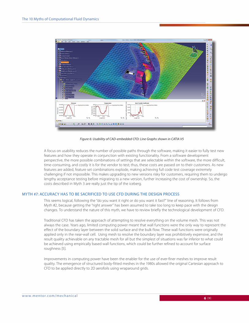
figure 6: usability of Cad-embedded Cfd: line graphs shown in CaTia v5

The 10 Myths of computational fluid dynamics
w w w. m ento r.co m /m e chanic al7 [9]
Such meshes were highly orthogonal2. When the approach was applied in 3D to irregularly shaped objects using unstructured meshes, non-orthogonality of the mesh meant that the construction of face-based fluxes needed to solve the mass, heat, and momentum balances for each cell was far more complex, and more critically, also involved significant mathematical approximations [6].
Small discrepancies between physical reality and simulation result for a mesh cell were transmitted to the neighbour cells by convection and diffusion as a natural part of the solution. Compounded across the mesh, this compromised overall solution accuracy. Solution convergence was also much harder to achieve. The effect of the variation in mesh quality was such that the physical effects of minor geometric variations were masked. This issue has plagued traditional body-fitted CFD ever since.
The industry has, of course, risen to the challenge in various ways: Increases in computing performance have allowed ever finer meshes to be used. More mesh allows the variation in size and shape from one mesh cell to the next to be reduced, improving orthogonality. Considerable effort has continued to be expended on the development of automated3 mesh generators, allowing mixtures of hexahedra, tetrahedral, and prisms to be used. More recently, polyhedral meshes, which have better orthogonality properties for any arbitrary flow direction4, have been constructed, e.g., by aggregating tetrahedra. Finally, more sophisticated numerical schemes that improve the estimation of cell face fluxes and pressure coupling have been devised.
2 meaning that a line joining the cell centers is perpendicular to the cell face, so calculation of cell-face fluxes for mass and momentum are simply the dot product of the area, velocity, and upstream fluid density.3 meaning only that the mesh is constructed according to an algorithmic method, not that it is fully automatic.4 important for large eddy Simulation (leS) where eddies cause the local flow direction to fluctuate over time.
figure 7: validation of a cyclone simulation for pressure drop and grade efficiency prediction
Straightener
Tangential inlet
deflecting cone
Bunker
dust outlet
Cone
Barrel
pressure drops of the cyclone under various temperatures
grade efficiency curves under volume flow rate of 60 m3/h and various air temperatures
vortex finder
overflow

The 10 Myths of computational fluid dynamics
w w w. m ento r.co m /m e chanic al8 [9]
In all but the highest fidelity cases, great accuracy can be achieved using conventional turbulence models with an immersed boundary treatment for wall friction and heat transfer [7]. This approach is around 100-times less expensive than traditional body-fitted RANS-based CFD, but delivers the same, or better, result accuracy [8]. It is perhaps for this reason, in recent years, Cartesian-based immersed-boundary codes have become popular, with a number of new market entrants [9]. Embedding this technology within CAD systems maximizes the benefit for industrial engineers, and by virtue of the CAD system being fully integrated into the PLM system, has the added benefit of minimizing the data management headache for engineering managers. CAD-embedded => PLM-embedded.
As noted above, using traditional CFD tools can take a long time and a lot of manual effort to construct and optimize the mesh to get the sufficient mesh quality and density for usefully accurate simulation results.
The new generation of CFD software, however, comes with key technologies that allow high-quality results to be obtained fast. In a matter of a few minutes, it is possible to construct an octree Cartesian-based mesh that automatically refines around solid–solid and solid–fluid interfaces, sidestepping the need to separately generate surface and volume meshes. Designers can control mesh density with a single slider, maximizing ease-of-use.
Being Cartesian, the mesh has the highest possible numerical mesh quality, because the cells in Cartesian and Cartesian-based meshes are perfectly orthogonal [6, 10]. Hence, it is not possible to improve the mesh quality through manual intervention. This unparalleled ease-of-use actually leads to a significant improvement of result accuracy, because the fidelity of the CFD simulation no longer has to be limited by project time constraints. In an industrial setting, engineers who are using traditional CFD do not have time to refine y+ values across the whole model even when the geometry is relatively simple. The more complex the geometry, the greater the benefit obtained from using octree Cartesian meshing. Octree Cartesian meshes are highly suited to solution-adaptive mesh refinement, where the mesh self-refines as the solution progresses to ensure that gradients are adequately captured, for example, in shock capture.
figure 8: validation of a micro turbine engine simulation performed with floefd
The model of KJ 66 engine in floefd fluid temperature distribution at two longitudinalsections with flow vectors at the normal mode
air mass flow at the inlet of KJ 66 engine
pressure surface distributions in the engine velocity distribution at two longitudinalsections with flow vectors at the normal mode
Thrust of KJ 66 engine

The 10 Myths of computational fluid dynamics
w w w. m ento r.co m /m e chanic al9 [9]
MyTh #8: experTs are needed To GeT accuraTe cfd siMulaTion resulTs
This myth still partly applies to traditional CFD, helping preserve Myth 1 within a broad cross-section of the CFD community, because near full-time use is required to gain and maintain a high level of proficiency. It is interesting that any two experts will always5 produce a different simulation result for any realistically complex industrial problem. They will generally disagree on whose result is the best one. This debunks the last line of defense in the argument for the involvement of expert analysts—that they are needed to check the results produced by non-experts.
Building in ease-of-use lowers the level of simulation-specific expertise needed, thereby allowing engineers to focus on the engineering problem. The numerical and physical modeling expertise of the software developers is accessed by the design engineer via the automation provided within the tool. Inputs are limited to what needs to be known about the problem being described: boundary conditions, materials, etc. applied directly to the native 3D geometry within the CAD system. Thus, non-simulation experts can get reliable, repeatable, high-quality simulation results.
As noted in the footnote earlier, an appropriate engineering background and domain expertise are necessary to understand the application being addressed to leverage the simulation results and improve the product design. However, automated optimization is already reducing the level of domain expertise needed to make design improvements. CAD-embedded CFD provides both parametric study and result comparison capabilities making design improvements easy to investigate.
We are in no way belittling the value of analysis experts. Such people are the very reason that CFD has grown to become what it is today, pioneering new applications that have driven the development of new physical and numerical models, etc. In late design, when the geometry is stable, traditional CFD can be applied, leveraging the
figure 9: Teenage students used floefd for ‘f1 in Schools’ competition
5 This is an axiom rather than a fact, as no two experts have to date independently achieved exactly the same simulation result for a real world engineering problem.
The 10 Myths of computational fluid dynamics
w w w. m ento r.co m /m e chanic al10 [9]
availability of analysis-ready CAD which is refined using a CAD-embedded CFD solution, to provide further design verification if desired. Alternatively, analysis experts can themselves use CAD-embedded CFD during design. CAD-embedded CFD and traditional CFD can, and arguably should, complement one another. CAD-embedded CFD also integrates well with other CAE tools used in product design, allowing temperature data to be exported as a thermal load for use in Creo Simulation and NASTRAN-based FEA solvers, among others, helping to accelerate other aspects of the design.
MyTh #9: producTion cad is Too coMplex To use for analysis
When working with exported CAD geometry, fitness for analysis depends greatly on how the original CAD model was created, the quality of the translator used to convert it into some neutral file format, the neutral format chosen, and how well the target analysis tool’s CAD import handles the import of that particular format. Unfortunately, once a CAD assembly is exported, much if not all of the parametric and history information (i.e., the software history of how the assembly, parts, and their features was built) is lost; and with it, the ability easily to detect and fix design mistakes is massively impaired. At this point, simplification and reconstruction of parts of the assembly can be the only option, both of which can give rise to errors.
Working with native CAD inside the MCAD system is a different story. Mistakes can be detected and fixed once only, and with relative ease directly within the main design workflow so the analysis geometry and design geometry are always in sync.
Concurrent CAD-embedded CFD tools based on Cartesian meshing are also highly tolerant to CAD errors, because a surface mesh is not required as part of the analysis process. Furthermore, minor features present in the CAD model that have no significance for the CFD analysis can be neglected by not using a sufficiently fine local mesh to resolve them. Conversely, small features such as joins and small gaps can be resolved to investigate their effect on the flow performance of the system. In CFD, small features often have a marked effect on flow performance, for example, by causing boundary layers to “trip” and the flow to separate. Geometry simplification is not needed; however, it is not prevented. It is relatively easy to prepare the geometry for efficient yet accurate analysis by using either the feature tree to control parts and features, and/or the de-featuring capabilities of the CAD system.
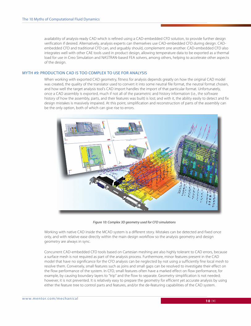
figure 10: Complex 3d geometry used for Cfd simulations

The 10 Myths of computational fluid dynamics
w w w. m ento r.co m /m e chanic al11 [9]
MyTh #10: concurrenT (cad-eMbedded) cfd Tools lack sophisTicaTion
This myth is based on the assumption that it is not possible to automate many of the more sophisticated features available in traditional CFD, and hence CFD tools that employ a high degree of automation must therefore exclude a lot of capabilities. The source of this myth is unknown. It may be grounded in the past experiences of analyst experts, gained years ago with stripped-down versions of traditional CFD tools, marketed as being for use with a particular CAD system; or it may be based on experiences of engineering designers using upfront CFD tools that also used body-fitted meshes; or it could be a combination of the two.
Despite the simplicity of the interface, CAD-embedded tools do not lack sophistication. Most, if not all, physical phenomena that are important to include in simulations involving fluid flow and heat transfer using CFD can be modeled using CAD-embedded CFD tools. Because of the direct access to 3D CAD data through underlying CAD kernel functions, it is possible to employ sophisticated algorithms for identifying the computational domain(s), generate mesh, intelligently apply physical conditions, and automatically adapt the solver configuration to capture the local physical situation, including solution adaptive meshing as mentioned earlier.
The choice to activate what might be considered as sophisticated CFD features – cavitation, combustion, condensation, water film evolution, erosion/accretion, non-Newtonian liquids, transonic, supersonic and hypersonic flows, moving/rotating parts, full conjugate heat transfer, radiation with spectral characteristics, refraction, reflection, and absorption (including solar radiation), Joule heating, and even the Peltier effect in thermoelectric devices – are all available as standard features, described using language that is familiar to any engineer.
closinG reMarks
We stand by our five original myths, and hope our revision has given you pause for thought. We invite you to think about these issues and give us your considered feedback.
If you have not yet considered using CFD to help your product design, we invite you to try our CAD-embedded Cartesian-based immersed boundary approach. For those of you that have experience of traditional body-fitted CFD and have a healthy scepticism of our approach, we say “just try it!” and sign up for a one-month trial [11].
figure 11: Cad-embedded Cfd uses complex physical models to predict the thermal behavior of a motorcycle headlight

The 10 Myths of computational fluid dynamics
©2014 Mentor Graphics corporation, all rights reserved. This document contains information that is proprietary to Mentor Graphics corporation and may be duplicated in whole or in part by the original recipient for internal business purposes only, provided that this entire notice appears in all copies. in accepting this document, the recipient agrees to make every reasonable effort to prevent unauthorized use of this information. all trademarks mentioned in this document are the trademarks of their respective owners.
F o r t h e l a t e s t p r o d u c t i n f o r m a t i o n , c a l l u s o r v i s i t : w w w . m e n t o r . c o m
MGc 07-14 Tech12210
references
1. “The Five Myths of Computational Fluid Dynamics”, NAFEMS BenchMARK magazine, April 2008, pp. 28-29.
2. “The Third Wave of CFD”, Ivo Weinhold and John Parry, Proceedings of the NAFEMS World Congress, Salzburg, Austria, June 2013.
3. Baldwin High School in Kansas Wins Second Real World Design Challenge (RWDC) National Aviation Design Competition Using Mentor Graphics FloEFD Technology http://www.mentor.com/company/news/baldwin-high-wins-second-real-world-design-challenge-using-floefd
4. “High School Students Fly with FloEFD™”, Mentor Graphics’ Engineering Edge Magazine, Vol 1, Iss. 1., http://www.mentor.com/products/mechanical/engineering-edge/volume1/issue1/high-school
5. “Turbulent Heat and Momentum Transfer in Rough Tubes”, M. R. Malin and J. D. Parry, The PHOENICS Journal of Computational Fluid Dynamics and its Applications, Vol. 1, No. 1, January 1988, pp. 59-80.
6. “Flomerics’ EFD Meshing Technology: A White Paper”, Drs. John Parry and David Tatchell
7. “Enhanced Turbulence Modeling in FloEFD”, Mentor Graphics Whitepaper MGC 02-11 TECH9670-W http://s3.mentor.com/public_documents/whitepaper/resources/mentorpaper_65206.pdf
8. “Concurrent CFD: PLM-Embedded Computational Fluid Dynamics for Upfront Product Design”, Drs. John Parry, CEng & Ivo Weinhold, Proceedings of NAFEMS World Congress, Boston MA, June 2011.
9. “Back To The Future – Trends In Commercial CFD”, Drs. Keith Hanna and John Parry, Proceedings of the NAFEMS World Congress, Boston MA, June 2011
10. “Advanced Immersed Boundary Cartesian Meshing Technology in FloEFD” MGC 02-11 TECH9690-W http://s3.mentor.com/public_documents/whitepaper/resources/mentorpaper_65169.pdf
11. FloEFD and FloTHERM XT, http://www.mentor.com/products/mechanical/
conTacT deTails
Dr. Ivo Weinhold [email protected] ; Dr. John Parry, CEng. [email protected]