100 north senate avenue michael r. pence, …...1 100 north senate avenue room n925 - cm...
TRANSCRIPT

1
100 North Senate Avenue Room N925 - CM Indianapolis, Indiana 46204
PHONE: (317) 232-5456 FAX: (317) 232-5551 Michael R. Pence, Governor
Brandye L. Hendrickson, Commissioner
AGENDA December 17, 2015 Standards Committee Meeting
MEMORANDUM December 01, 2015 TO: Standards Committee FROM: Scott Trammell, Secretary RE: Agenda for the December 17, 2015 Standards Committee Meeting A Standards Committee meeting is scheduled for 09:00 a.m. on December 17, 2015 in the N955 Bay Window Conference Room. Please enter meeting through the double doors directly in front of the conference room. The following items are listed for consideration: A. GENERAL BUSINESS ITEMS OLD BUSINESS (No items on this agenda) NEW BUSINESS 1. Approval of the Minutes from the August 20, 2015 meeting 2. Approval of the Standards Committee’s schedule of meetings,
submittals and distribution for 2016 ............pg 03, Mr. Trammell B. CONCEPTUAL PROPOSAL ITEMS OLD BUSINESS (No items on this agenda) NEW BUSINESS 1. Introduction of the unique special provision (USP) for Truck
Mounted Attenuators .............................pg 04, Ms. Phillips

(CONTINUED)
2
C. STANDARD SPECIFICATIONS, SPECIAL PROVISIONS AND STANDARD DRAWINGS PROPOSED ITEMS OLD BUSINESS (No items on this agenda) NEW BUSINESS Item No. 01 (2016 SS) Ms. Phillips pg 09 702.27 Method of Measurement 702.28 Basis of Payment Item No. 02 (2016 SS) Mr. Pankow pg 13 104.07 Rights In and Use of Materials
Found In the Project Site Item No. 03 (2016 SS) Mr. Boruff pg 17 922.04(a)1 Housing, Door, and Visor Item No. 04 (2016 SS) Mr. Boruff pg 21 805.03 General Requirements Item No. 05 (2016 SS) Mr. Boruff pg 25 Recurring Special Provisions: 801-T-XXX PORTABLE TRAFFIC SIGNALS 801-T-XXXd TEMPORARY SIGNAL TIMING PLAN 801-T-XXXd PORTABLE SIGNAL INSPECTION
CHECKLIST Item No. 06 (2016 SS) Mr. Beeson pg 40 Recurring Special Provision: 413-R-XXX FULL DEPTH RECLAMATION, FDR Item No. 07 (2016 SS) Mr. Boruff pg 52 Recurring Special Provision: 808-T-210 GROOVING FOR DURABLE PAVEMENT
MARKINGS Item No. 08 (2016 SS) Mr. Boruff pg 64 Recurring Special Provision: 926-R-XXX DELINEATORS MATERIALS Item No. 09 (2016 SS) Mr. Beeson pg 68 411.03 Design Mix Formula 411.06 Preparation of Surfaces cc: Committee Members FHWA ICA

(CONTINUED)
3

Ms. Phillips Date: 12/17/15
CONCEPTUAL ITEM 01. UNIQUE SPECIAL PROVISION: TRUCK MOUNTED ATTENUATORS
4
PROPOSAL TO STANDARDS COMMITTEE
PROBLEM(S) ENCOUNTERED: A need to provide basis of payment, and guidance for required deployment for Truck Mounted Attenuators (TMA) for safety on construction projects. Projects of specific interest are projects that require short lane closures on the Interstate. PROPOSED SOLUTION: A USP has been developed that pays the contractor per day of use for each TMA that is used on a construction project. Some drawings have been developed that provide guidance to designers on how to layout the work zone for lane closures in accordance with the Indiana MUTCD. APPLICABLE STANDARD SPECIFICATIONS: none at this time, but eventually 801. APPLICABLE STANDARD DRAWINGS: Created Single Lane Closure and Double Lane Closure APPLICABLE DESIGN MANUAL SECTION: none at this time APPLICABLE SECTION OF GIFE: n/a APPLICABLE RECURRING SPECIAL PROVISIONS: n/a PAY ITEMS AFFECTED: Pay Item for Truck Mounted Attenuator [Day] 801-12042 APPLICABLE SUB-COMMITTEE ENDORSEMENT: Office of Bridge Design - Jeremy Hunter, Stephanie Wagner. Comments solicited from FHWA, Division of Construction, and ICA Submitted By: Elizabeth Phillips Title: Standards and Policy Manager Organization: Bridges Division Phone Number: 232-6775 Date: 11/16/15

Ms. Phillips Date: 12/17/15
CONCEPTUAL ITEM 01. (CONTINUED) UNIQUE SPECIAL PROVISION: TRUCK MOUNTED ATTENUATORS
5
TRUCK MOUNTED ATTENUATORS
Description This work shall consist of furnishing truck mounted attenuators, TMA’s, in accordance with 105.03. Materials Materials shall be in accordance with 801.02 and as follows: Each truck-mounted attenuator shall be in accordance with the appropriate TL-2 or TL-3 NCHRP 350 or MASH crash testing requirements. TL-2 or TL-3 units shall be used where the work zone speed limit is 45 mph or less. TL-3 units shall be required where the work zone speed limit is 50 mph or greater. The FHWA eligibility letter for each unit shall be provided prior to use. All units shall be in good working condition. Construction Requirements When utilized, the truck mounted attenuators shall be used in accordance with 801.03 and the Indiana Manual of Uniform Traffic Control Devices, MUTCD, and the manufacturer’s recommendations. Truck mounted attenuators shall be energy absorbing devices attached to the rear of shadow trailers or trucks. When used, the shadow vehicle with the attenuator shall be positioned a sufficient distance in advance of the work area, workers, or equipment to reduce the severity of rear end collisions from errant vehicles, but not so far in advance that errant vehicles can travel around the shadow vehicle and endanger the workers or equipment. The Contractor shall provide additional shadow vehicles for any gaps in the operation of 500 ft or more. A truck mounted attenuator may be used on the work vehicle and the shadow vehicle. Where a TMA remains stationary for extended periods of time, the Contractor may utilize a barrier trailer in lieu of a barrier vehicle. TMA units shall be maintained in such a manner as to provide continuous service. Where a unit becomes inoperable, work shall be suspended until the unit is repaired or replaced. No time extension will be considered for delays due to inoperable units. Method of Measurement Truck mounted attenuators will be measured by the number of calendar days that each unit is in use. Basis of Payment The accepted quantities of truck mounted attenuators will be paid for at the contract unit price per each unit per calendar day that unit

Ms. Phillips Date: 12/17/15
CONCEPTUAL ITEM 01. (CONTINUED) UNIQUE SPECIAL PROVISION: TRUCK MOUNTED ATTENUATORS
6
is utilized. Payment will be made only once for each day of use, regardless of the number of times the attenuators are moved to accommodate different phases of traffic maintenance or construction operations as shown in the contract. Payment will be made under: Pay Item Pay Unit Symbol Truck Mounted Attenuator...........................DAY The cost of furnishing the truck, trailer, flashing arrow sign, and mounted impact attenuator shall be included in the cost of the pay item. No additional payment will be made for maintenance, repairs, or replacement of units that are damaged or become inoperable.

Ms. Phillips Date: 12/17/15
CONCEPTUAL PROPOSAL ITEM 01 (CONTINUED) LANE CLOSURE SHEET 1 of 2
7

Ms. Phillips Date: 12/17/15
CONCEPTUAL PROPOSAL ITEM 01 (CONTINUED) LANE CLOSURE SHEET 2 of 2
8

Ms. Phillips Date: 12/17/15
STANDARD SPECIFICATIONS, SPECIAL PROVISIONS AND STANDARD DRAWINGS REVISION TO STANDARD SPECIFICATIONS
9
PROPOSAL TO STANDARDS COMMITTEE
PROBLEM(S) ENCOUNTERED: After a proposal to Standards Committee dated 3/15/2012, changes were made to Std. Drawing #s E 704-BDCG -01 thru E 704-BDCG -05. Subsequently, the weight of Type OS and Type SQ Roadway drains was removed from the Standard drawings. Presently, pay item units for, Item # 702-51110, for Grates, Basins and Fittings for OS and SQ drain castings are inconsistent with units for other types of drainage castings. This creates confusion for Consultants and Construction. PROPOSED SOLUTION: Change the pay item from LBS to EACH for type SQ and OS drain and adjusting frame castings. APPLICABLE STANDARD SPECIFICATIONS: 702.28 APPLICABLE STANDARD DRAWINGS: E704-BDCG-01 thru E704-BDCG-05 APPLICABLE DESIGN MANUAL SECTION NA APPLICABLE SECTION OF GIFE: NA APPLICABLE RECURRING SPECIAL PROVISIONS: NA PAY ITEMS AFFECTED: 702-51110, Gratings, Basins and Fittings, Cast Iron APPLICABLE SUB-COMMITTEE ENDORSEMENT: Ad hoc Standards, comprised of Elizabeth Phillips and Naveed Burki IMPACT ANALYSIS (attach report): yes Submitted By: Naveed Burki for Elizabeth Phillips Title: Standards Engineer Organization: INDOT Phone Number: 317-1233-2057 Date: 5/29/2015
Ms. Phillips Date: 12/17/15
STANDARD SPECIFICATIONS, SPECIAL PROVISIONS AND STANDARD DRAWINGS REVISION TO STANDARD SPECIFICATIONS
10
IMPACT ANALYSIS REPORT CHECKLIST
Explain the business case as to why this item should be presented to the Standards Committee for approval. Answer the following questions with Yes, No or N/A. Does this item appear in any other specification sections? No Will approval of this item affect the Approved Materials List? No Will this proposal improve:
Construction costs? Yes
Construction time? No
Customer satisfaction? yes
Congestion/travel time? No
Ride quality? No
Will this proposal reduce operational costs or maintenance effort? No Will this item improve safety: For motorists? No
For construction workers? No Will this proposal improve quality for:
Construction procedures/processes? Yes
Asset preservation? No
Design process? Yes
Will this change provide the contractor more flexibility? Yes Will this proposal provide clarification for the Contractor and field personnel? yes Can this item improve/reduce the number of potential change orders? Yes Is this proposal needed for compliance with:
Federal or State regulations? Yes
AASHTO or other design code? Yes
Is this item editorial? No Provide any further information as to why this proposal should be placed on the Standards Committee meeting Agenda: This will make the pay items for the Type OS and SQ drains as EACH instead of in LBS, which will be consistent with the pay item of all types of gratings.

Item No.01 12/17/15 (2016 SS) (contd.) Ms. Phillips Date: 12/17/15 REVISION TO STANDARD SPECIFICATIONS SECTION 702 – STRUCTURAL CONCRETE 702.27 METHOD OF MEASUREMENT 702.28 BASIS OF PAYMENT
11
The Standard Specifications are revised as follows: SECTION 702, BEGIN LINE 1372, DELETE AND INSERT AS FOLLOWS: Cast iron grates, basins, and fittings will be measured by the pound based on the theoretical weight shown on the plansper each. The volume will be computed based on finished dimensions. Drainage pipe through concrete masonry will be measured in accordance with 715. Field drilled holes will be measured by the number of holes drilled. Concrete in railings will be measured in accordance with 706.07. Reinforcing bars will be measured in accordance with 703.07. 702.28 Basis of Payment The accepted quantities of structural concrete will be paid for at the contract unit price per cubic yard of concrete, for the class and use specified. Cast iron grates, basins, and fittings will be paid for at the contract unit price per pound each. Steel drain pipe will be paid for at the contract lump sum price. Field drilled holes in concrete will be paid for at the contract unit price per each. SECTION 702, BEGIN LINE 1421, DELETE AND INSERT AS FOLLOWS: Grates, Basins, and Fittings, Cast Iron .............................................. LBSEACH

Item No.01 12/17/15 (2016 SS) (contd.) Ms. Phillips Date: 12/17/15 COMMENTS AND ACTION 702.27 METHOD OF MEASUREMENT 702.28 BASIS OF PAYMENT
12
DISCUSSION:
Motion: Second: Ayes: Nays: FHWA Approval:
Action: Passed as Submitted Passed as Revised __ __ Withdrawn
Standard Specifications Sections referenced and/or affected:
702.27 pg 547 and 548. Recurring Special Provision affected:
NONE Standard Drawing affected:
NONE Design Manual Sections affected:
NONE GIFE Sections cross-references:
NONE
2018 Standard Specifications Revise Pay Items List Create RSP (No. ) Effective Letting RSP Sunset Date: Revise RSP (No. ) Effective Letting RSP Sunset Date: Standard Drawing Effective Create RPD (No. ) Effective Letting GIFE Update

Mr. Pankow Date: 12/17/15
STANDARD SPECIFICATIONS, SPECIAL PROVISIONS AND STANDARD DRAWINGS REVISION TO STANDARD SPECIFICATIONS
13
PROPOSAL TO STANDARDS COMMITTEE
PROBLEM(S) ENCOUNTERED: The possibility of payment for anticipated salvaged material costs has been an issue of potential problematic concern to the Department. PROPOSED SOLUTION: Proposed specification language additions reduce the potential for associated costs with anticipated salvaged material concerns. APPLICABLE STANDARD SPECIFICATIONS: 104.07 APPLICABLE STANDARD DRAWINGS: N/A APPLICABLE DESIGN MANUAL SECTION: N/A APPLICABLE SECTION OF GIFE: N/A APPLICABLE RECURRING SPECIAL PROVISIONS: N/A PAY ITEMS AFFECTED: Any item that would be affected by a potential salvage material cost. APPLICABLE SUB-COMMITTEE ENDORSEMENT: Ad hoc IMPACT ANALYSIS (attach report): yes Submitted By: Greg Pankow Title: State Construction Engineer Organization: Construction Management and District Support Phone Number: 317-232-0676 Date: October 15, 2015

Mr. Pankow Date: 12/17/15
STANDARD SPECIFICATIONS, SPECIAL PROVISIONS AND STANDARD DRAWINGS REVISION TO STANDARD SPECIFICATIONS
14
IMPACT ANALYSIS REPORT CHECKLIST
Explain the business case as to why this item should be presented to the Standards Committee for approval. Answer the following questions with Yes, No or N/A. Does this item appear in any other specification sections? No Will approval of this item affect the Approved Materials List? No Will this proposal improve:
Construction costs? Yes
Construction time? No
Customer satisfaction? No
Congestion/travel time? No
Ride quality? No
Will this proposal reduce operational costs or maintenance effort? No Will this item improve safety: For motorists? No
For construction workers? No Will this proposal improve quality for:
Construction procedures/processes? Yes
Asset preservation? No
Design process? No
Will this change provide the contractor more flexibility? Unknown Will this proposal provide clarification for the Contractor and field personnel? Yes Can this item improve/reduce the number of potential change orders? Yes Is this proposal needed for compliance with:
Federal or State regulations? No
AASHTO or other design code? No
Is this item editorial? No Provide any further information as to why this proposal should be placed on the Standards Committee meeting Agenda:

Item No.02 12/17/15 (2016 SS) (contd.) Mr. Pankow Date: 12/17/15 REVISION TO STANDARD SPECIFICATION SECTION 104 – SCOPE OF WORK 104.07 RIGHTS IN AND USE OF MATERIALS FOUND IN THE PROJECT SITE
15
The Standard Specifications are revised as follows: SECTION 104, BEGIN LINE 521, INSERT AS FOLLOWS: 104.07 Rights in and Use of Materials Found in the Project Site Except for hazardous wastes, hazardous substances, hazardous materials, and asbestos which are subject to 104.06, and lead and zinc bridge painting debris which is subject to 619, all materials designated to be removed from the project and not used in the work shall become the property of the Contractor, unless otherwise set out in the Proposal book. The value of these materials shall be taken into account when the bid is being prepared. The Department does not guarantee that any amount or value of salvaged materials will be available to the Contractor. The Contractor shall have no claim against the Department if the actual amount or value of salvaged materials differs from the amount or value the Contractor expected or anticipated. Construction materials such as gravel, stone, or sand found in the excavation shall not be used for purposes other than indicated on the plans without written approval. When such approval is given, it shall state explicitly the provisions under which it is granted. On all contracts involving construction within the corporate limits of cities and towns in which items such as drainage structure castings, or other items having a salvage value, are to be removed, the removed items shall remain the property of the governmental bodies involved if so specified in the Proposal book or on the plans. Otherwise, these items shall be disposed of in accordance with these Standard Specifications. The cost of such disposal shall be included in the contract unit prices of the various pay items of the contract, unless otherwise provided. Archaeological artifacts encountered during construction shall be addressed in accordance with 107.10.

Item No.02 12/17/15 (2016 SS) (contd.) Mr. Pankow Date: 12/17/15 COMMENTS AND ACTION 104.07 RIGHTS IN AND USE OF MATERIALS FOUND IN THE PROJECT SITE
16
DISCUSSION:
Motion: Second: Ayes: Nays: FHWA Approval:
Action: Passed as Submitted Passed as Revised __ __ Withdrawn
Standard Specifications Sections referenced and/or affected:
107.04 pg 40. Recurring Special Provision affected:
NONE Standard Drawing affected:
NONE Design Manual Sections affected:
NONE GIFE Sections cross-references:
NONE
2018 Standard Specifications Revise Pay Items List Create RSP (No. ) Effective Letting RSP Sunset Date: Revise RSP (No. ) Effective Letting RSP Sunset Date: Standard Drawing Effective Create RPD (No. ) Effective Letting GIFE Update

Mr. Boruff Date: 12/17/15
STANDARD SPECIFICATIONS, SPECIAL PROVISIONS AND STANDARD DRAWINGS REVISION TO STANDARD SPECIFICATIONS
17
PROPOSAL TO STANDARDS COMMITTEE
PROBLEM(S) ENCOUNTERED: Occasionally, pedestrian signal heads are installed in such a way that the housing and hardware do not allow for full rotation in 5° increments. Improvement is needed to the wording in §922.04 regarding the rotation requirements. PROPOSED SOLUTION: Amend the standard specifications to clarify that the pedestrian signal head housing and hardware must allow the pedestrian signal head to be capable of rotating in 5° increments. The revision is mainly editorial and could be incorporated into the 2018 Standard Specifications, an interim RSP is not necessary. APPLICABLE STANDARD SPECIFICATIONS: 922.04 APPLICABLE STANDARD DRAWINGS: N/A APPLICABLE DESIGN MANUAL SECTION: N/A APPLICABLE SECTION OF GIFE: N/A APPLICABLE RECURRING SPECIAL PROVISIONS: N/A PAY ITEMS AFFECTED: N/A APPLICABLE SUB-COMMITTEE ENDORSEMENT: Ad hoc review by INDOT district maintenance staff. IMPACT ANALYSIS (attach report): Yes, attached. Submitted By: Dave Boruff Title: Manager, Office of Traffic Administration Organization: INDOT Phone Number: (317) 234-7975 Date: 9/17/15

Mr. Boruff Date: 12/17/15
STANDARD SPECIFICATIONS, SPECIAL PROVISIONS AND STANDARD DRAWINGS REVISION TO STANDARD SPECIFICATIONS
18
IMPACT ANALYSIS REPORT CHECKLIST
Explain the business case as to why this item should be presented to the Standards Committee for approval. Answer the following questions with Yes, No or N/A. Does this item appear in any other specification sections? No Will approval of this item affect the Approved Materials List? No Will this proposal improve: Construction costs? No
Construction time? No
Customer satisfaction? Yes
Congestion/travel time? No
Ride quality? Yes
Will this proposal reduce operational costs or maintenance effort? Yes Will this item improve safety: For motorists? Yes, and for pedestrians that
may not have a good angle for viewing the pedestrian signal head at a
particular location.
For construction workers? No
Will this proposal improve quality for: Construction procedures/processes? No
Asset preservation? Yes
Design process? No
Will this change provide the contractor more flexibility? No Will this proposal provide clarification for the Contractor and field personnel? Yes Can this item improve/reduce the number of potential change orders? Yes Is this proposal needed for compliance with: Federal or State regulations? No
AASHTO or other design code? No
Is this item editorial? Yes
Provide any further information as to why this proposal should be placed on the Standards Committee meeting Agenda: N/A

Item No.03 12/17/15 (2016 SS) (contd.) Mr. Boruff Date: 12/17/15 REVISION TO STANDARD SPECIFICATION SECTION 922 – TRAFFIC SIGNAL MATERIALS AND EQUIPMENT 922.04(a)1 HOUSING, DOOR, AND VISOR
19
The Standard Specifications are revised as follows: SECTION 922, BEGIN LINE 779, DELETE AND INSERT AS FOLLOWS 1. Housing, Door, and Visor The housing shall be equipped with mounting device hardware, such as a clamshell, and with round openings at the top and bottom for mounting with brackets made of iron pipe standard, to fit the 1 1/2 in. pipe. The round openings shall have a common vertical centerline through the housing to allow 360ofor rotation after it is mounted. The round openings shall have a serrated ring, with 72 serrations, which enables locking of the housing in 5o increments throughout the entire 360o of rotation. The brackets or the clamshell shall serve as the electrical conduit for the pedestrian signal. The housing shall be black and made of die-cast, corrosion resistant, copper free, non-ferrous metal which shall be in accordance with ASTM B 85.

Item No.03 12/17/15 (2016 SS) Mr. Boruff Date: 12/17/15 COMMENTS AND ACTION 922.04(a)1 HOUSING, DOOR, AND VISOR
20
DISCUSSION:
Motion: Second: Ayes: Nays: FHWA Approval:
Action: Passed as Submitted Passed as Revised __ __ Withdrawn
Standard Specifications Sections referenced and/or affected:
922.04(a)1 pg 1050. Recurring Special Provision affected:
NONE Standard Drawing affected:
NONE Design Manual Sections affected:
NONE GIFE Sections cross-references:
NONE
2018 Standard Specifications Revise Pay Items List Create RSP (No. ) Effective Letting RSP Sunset Date: Revise RSP (No. ) Effective Letting RSP Sunset Date: Standard Drawing Effective Create RPD (No. ) Effective Letting GIFE Update

Mr. Boruff Date: 12/17/15
STANDARD SPECIFICATIONS, SPECIAL PROVISIONS AND STANDARD DRAWINGS REVISION TO STANDARD SPECIFICATIONS
21
PROPOSAL TO STANDARDS COMMITTEE
PROBLEM(S) ENCOUNTERED: Around 2009 the International Municipal Signal Association (IMSA) separated the Level II Traffic Signal Technician into the Level II Traffic Signal Construction Technician and the Level II Traffic Signal Field Technician. The signal construction requirements in INDOT’s Standard Specifications generally accept either Level II certification, but the relevant paragraph is inconsistent. After review the Traffic Control Systems Division determined that either IMSA Level II certification is acceptable. PROPOSED SOLUTION: Modify Section 805.03 to clarify that the signal controller may be set-up by either an IMSA Level II Traffic Signal Field Technician or an IMSA Level II Traffic Signal Construction Technician. APPLICABLE STANDARD SPECIFICATIONS: 805.03 APPLICABLE STANDARD DRAWINGS: N/A APPLICABLE DESIGN MANUAL SECTION: N/A APPLICABLE SECTION OF GIFE: Section 2.9 APPLICABLE RECURRING SPECIAL PROVISIONS: N/A PAY ITEMS AFFECTED: N/A APPLICABLE SUB-COMMITTEE ENDORSEMENT: Ad hoc review by Contractor Prequalification Section and the Traffic Control Systems Division. IMPACT ANALYSIS (attach report): Yes Submitted By: Dave Boruff Title: Manager, Office of Traffic Administration Organization: INDOT Phone Number: (317) 234-7975 Date: 11/23/2015

Mr. Boruff Date: 12/17/15
STANDARD SPECIFICATIONS, SPECIAL PROVISIONS AND STANDARD DRAWINGS REVISION TO STANDARD SPECIFICATIONS
22
IMPACT ANALYSIS REPORT CHECKLIST
Explain the business case as to why this item should be presented to the Standards Committee for approval. Answer the following questions with Yes, No or N/A. Does this item appear in any other specification sections? No Will approval of this item affect the Approved Materials List? No Will this proposal improve:
Construction costs? No
Construction time? No
Customer satisfaction? No
Congestion/travel time? No
Ride quality? No
Will this proposal reduce operational costs or maintenance effort? No Will this item improve safety:
For motorists? No
For construction workers? No Will this proposal improve quality for: Construction procedures/processes? No
Asset preservation? No
Design process? No
Will this change provide the contractor more flexibility? Yes Will this proposal provide clarification for the Contractor and field personnel? Yes Can this item improve/reduce the number of potential change orders? No Is this proposal needed for compliance with: Federal or State regulations? No
AASHTO or other design code? No Is this item editorial? Yes Provide any further information as to why this proposal should be placed on the Standards Committee meeting Agenda: N/A

Item No.04 12/17/15 (2016 SS) (contd.) Mr. Boruff Date: 12/17/15 REVISION TO STANDARD SPECIFICATIONS SECTION 805 – TRAFFIC SIGNALS 805.03 GENERAL REQUIREMENTS
23
(Proposed changes shown highlighted gray) The Standard Specifications are revised as follows: SECTION 805, BEGIN LINE 103, DELETE AND INSERT AS FOLLOWS: All electrical wiring terminations and splices; controller and cabinet set-up; and testing, review, and turn-on of all operational apparatus at each location shall be done by or in the presence of and under the responsible charge of an employee of the Contractor who holds aan IMSA Traffic Signal Construction Technician Level II certification or an IMSA Traffic Signal Field Technician Level II certification which has been granted by the International Municipal Signal Association. Installation inspections, troubleshooting, maintenance and repair of these systems shall be accomplished by or in the presence of and under the responsible charge of an employee of the Contractor who holds a an IMSA Traffic Signal Construction Technician Level II certification or a Traffic Signal Field Technician Level II certification which has been granted by the International Municipal Signal Association. Supervision of non-electrical, traffic signal related construction work and traffic control shall be done by a person holding, at a minimum, a an IMSA Work Zone Traffic Safety Specialist Temporary Traffic Control Technician certification which has been granted by the International Municipal Signal Association, or an equivalent certification approved by the Department. Before starting work, the Contractor shall provide the names of the Level II Traffic Signal Construction Technicians, the Level II Traffic Signal Field Technicians and Work Zone Traffic Safety SpecialistsTemporary Traffic Control Technicians who have been assigned to perform signal related work, and a photocopy of each such person’s certification card. If the Level II Traffic Signal Construction or Field Technicians or Work Zone Safety SpecialistsTemporary Traffic Control Technicians are dismissed from the work, all signal related work requiring such certified personnel on the project site shall cease until the names and photocopies of certification cards for replacement personnel are provided to the Engineer.

Item No.04 12/17/15 (2016 SS) (contd.) Mr. Boruff Date: 12/17/15 COMMENTS AND ACTION 805.03 GENERAL REQUIREMENTS
24
DISCUSSION:
Motion: Second: Ayes: Nays: FHWA Approval:
Action: Passed as Submitted Passed as Revised __ __ Withdrawn
Standard Specifications Sections referenced and/or affected:
805.03 pg 784. Recurring Special Provision affected:
NONE Standard Drawing affected:
NONE Design Manual Sections affected:
NONE GIFE Sections cross-references:
Section 2.9
2018 Standard Specifications Revise Pay Items List Create RSP (No. ) Effective Letting RSP Sunset Date: Revise RSP (No. ) Effective Letting RSP Sunset Date: Standard Drawing Effective Create RPD (No. ) Effective Letting GIFE Update

Mr. Boruff Date: 12/17/15
STANDARD SPECIFICATIONS, SPECIAL PROVISIONS AND STANDARD DRAWINGS REVISION TO STANDARD SPECIFICATIONS AND SPECIAL PROVISIONS
25
PROPOSAL TO STANDARDS COMMITTEE
PROBLEM(S) ENCOUNTERED: In 2014, there were 93 temporary traffic signals used on contracts with a total cost of nearly $5 million dollars. In many cases these temporary traffic signals are used for only a month and it would be considerably more economical to use portable traffic signals, which are solar powered and mounted on trailers instead of the wood poles. Getting the electric utility service to temporary traffic signals can also cause significant project delays, particularly on bridge work in remote locations. PROPOSED SOLUTION: Establish a recurring special provision for portable traffic signals. Design guidance will be established concurrently with this recurring special provision. The Indiana MUTCD has already been revised to allow portable traffic signals and an Indiana Test Method was recently created so that there can be an approved materials list for this device. APPLICABLE STANDARD SPECIFICATIONS: 801.15(d), 801.17 and 801.18 APPLICABLE STANDARD DRAWINGS: No APPLICABLE DESIGN MANUAL SECTION: 83-5.0 APPLICABLE SECTION OF GIFE: No APPLICABLE RECURRING SPECIAL PROVISIONS: No PAY ITEMS AFFECTED: Yes APPLICABLE SUB-COMMITTEE ENDORSEMENT: Yes, Traffic Standards Subcommittee IMPACT ANALYSIS (attach report): Yes, attached. Submitted By: Dave Boruff Title: Manager, Office of Traffic Administration Organization: INDOT Phone Number: (317) 234-7975 Date: 11/23/2015

Mr. Boruff Date: 12/17/15
STANDARD SPECIFICATIONS, SPECIAL PROVISIONS AND STANDARD DRAWINGS REVISION TO STANDARD SPECIFICATIONS AND SPECIAL PROVISIONS
26
IMPACT ANALYSIS REPORT CHECKLIST Explain the business case as to why this item should be presented to the Standards Committee for approval. Answer the following questions with Yes, No or N/A. Does this item appear in any other specification sections? No Will approval of this item affect the Approved Materials List? No Will this proposal improve:
Construction costs? Yes
Construction time? Yes
Customer satisfaction? Yes
Congestion/travel time? No
Ride quality? No Will this proposal reduce operational costs or maintenance effort? Yes Will this item improve safety:
For motorists? No
For construction workers? No Will this proposal improve quality for: Construction procedures/processes? Yes
Asset preservation? No
Design process? No
Will this change provide the contractor more flexibility? Yes Will this proposal provide clarification for the Contractor and field personnel? Yes Can this item improve/reduce the number of potential change orders? Yes Is this proposal needed for compliance with: Federal or State regulations? No
AASHTO or other design code? No
Is this item editorial? No Provide any further information as to why this proposal should be placed on the Standards Committee meeting Agenda: N/A

Item No.05 12/17/15 (2016 SS) (contd.) Mr. Boruff Date: 12/17/15 REVISION TO STANDARD SPECIFICATIONS AND SPECIAL PROVISIONS PROPOSED NEW 801-T-XXX PORTABLE TRAFFIC SIGNALS
27
(Proposed changes shown highlighted gray)
801-T-XXX PORTABLE TRAFFIC SIGNALS
(Adopted XX-XX-15) The Standard Specifications are revised as follows: SECTION 801, BEGIN LINE 750, DELETE AND INSERT AS FOLLOWS: (d) Temporary Traffic Signals This work shall consist of furnishing, installing, and maintaining temporary traffic signals in accordance with 805 except as modified herein. Except as shown on the plans, all materials not furnished by the Department shall remain the property of the Contractor after work is completed and the equipment is removed. The traffic signal equipment shall be as specified, but may be either new or used. Used equipment shall be in satisfactory working condition and will be approved prior to use. Two signal heads shall be displayed for each approach. Signals shall be displayed overhead on a span, catenary, and tether utilizing an aircraft cable, unless otherwise directed. Signal cable may be extended across bridges through conduit which shall be attached to the underside of the coping. Type and spacing of clamps shall be approved prior to installation. Conduit shall be steel or plastic. Flexible conduit will be an acceptable alternate for use as ground rod entry, magnetometer, or microloop installations. Vehicle detection, if required, shall be installed as shown on the plans or as otherwise directed and shall be operational prior to signal activation. 1. Fixed Temporary Signals Fixed temporary signals shall be displayed overhead on a span, catenary, and tether utilizing an aircraft cable, unless otherwise directed. Electric energy necessary to power the fixed temporary signal is the responsibility of the Contractor. Prior to the start of construction, the schedule of activities shall be coordinated with the power company. The Contractor shall obtain permits from local officials, companies, or individuals for the use of poles, right-of-way, or other property incidental to the installation of fixed temporary signals. Although entering into the contract implies permission and authority to install conduit under pavement, sidewalks, and alleys, all damage to underground utilities or interruption of such service shall be the responsibility of the Contractor.

Item No.05 12/17/15 (2016 SS) (contd.) Mr. Boruff Date: 12/17/15 REVISION TO STANDARD SPECIFICATIONS AND SPECIAL PROVISIONS PROPOSED NEW 801-T-XXX PORTABLE TRAFFIC SIGNALS
28
The location, spacing, and timing of fixed temporary signals will be determined by the Engineer. An IMSA certified level II traffic signal construction technician or a level II traffic signal field technician shall be available 24 h a day to respond within 2 h for the maintenance of the traffic signal equipment. Signal cable may be extended across bridges through conduit which shall be attached to the underside of the coping. Type and spacing of clamps shall be approved prior to installation. Conduit shall be steel or plastic. Flexible conduit will be an acceptable alternate for use as ground rod entry, magnetometer, or microloop installations. The controller shall be solid state digital. When detection is required, the controller shall be traffic actuated solid state, digital. Vehicle detection, if required, shall be installed as shown on the plans or as otherwise directed and shall be operational prior to signal activation. 2. Portable Signals Portable signals shall be selected from the Department’s list of approved Portable Signals. Prior to the activation the Contractor shall provide a completed inspection checklist to the Engineer certifying that the portable signal is functioning properly. The portable signal shall be equipped with remote monitoring. Drums shall be placed immediately in front of the portable signal trailer at both corners for delineation. A technician certified by the manufacturer shall be available 24 h a day to respond within 2 h for the maintenance of the traffic signal equipment – a copy of the certification shall be provided to the Engineer prior to the placement of the portable signals. Maintenance of the portable signal includes adjustments to the phasing or timing as indicated on the plans or directed by the Engineer. The Contractor shall replace portable signals that cannot be returned to normal operation or that fail two times during the contract. The Contractor shall provide a record of any modifications to the signal timing plan, failures, and all maintenance issues, to the Engineer prior to final acceptance and when otherwise requested. The report shall indicate the date, time, and nature of each event.

Item No.05 12/17/15 (2016 SS) (contd.) Mr. Boruff Date: 12/17/15 REVISION TO STANDARD SPECIFICATIONS AND SPECIAL PROVISIONS PROPOSED NEW 801-T-XXX PORTABLE TRAFFIC SIGNALS
29
SECTION 801, BEGIN LINE 887, DELETE AND INSERT AS FOLLOWS: Flashing arrow signs and portable signals will be measured by the number of calendar days each unit is operated. Patroller will be measured by the number of calendar days during the phase or phases of traffic control, as shown on the plans or as otherwise directed, that require the patroller’s presence. Each portion of a day will be measured as a whole day. Temporary illumination, fixed temporary traffic signals, and maintaining traffic will not be measured for payment. SECTION 801, BEGIN LINE 975, INSERT AS FOLLOWS: Flashing arrow signs, portable signals, and patrollers will be paid for at the contract unit price per day per each. SECTION 801, BEGIN LINE 1009, DELETE AND INSERT AS FOLLOWS: The accepted fixed temporary traffic signal, complete in place and later removed as specified, will be paid for at the contract lump sum price. SECTION 801, BEGIN LINE 1030, INSERT AS FOLLOWS: Patroller ............................................................................... DAY Portable Changeable Message Sign .................................. EACH Portable Signal..................................................................... DAY Road Closure Sign Assembly............................................ EACH SECTION 801, BEGIN LINE 1058, DELETE AND INSERT AS FOLLOWS: Fixed Temporary Traffic Signal .............................................. LS SECTION 801, AFTER LINE 1166, DELETE AND INSERT AS FOLLOWS: The cost of the vehicle detection, solar panel, battery cabinet, program timing module, signal heads, wiring, trailer, and all hardware required shall be included in the cost of the portable traffic signal. Electric energy necessary to power luminaires and fixed temporary traffic signals will not be paid for.

Item No.05 12/17/15 (2016 SS) (contd.) Mr. Boruff Date: 12/17/15 REVISION TO STANDARD SPECIFICATIONS AND SPECIAL PROVISIONS PROPOSED NEW 801-T-XXXd TEMPORARY SIGNAL TIMING PLAN
30
801-T-XXXd TEMPORARY SIGNAL TIMING PLAN
(Adopted XX-XX-2015) Intersection: Contract No.: Official Action #: Controller Type: Temporary Traffic Signal Portable Traffic Signal Intersection Operation: Pre-Timed Semi-Actuated Fully Actuated
Preemption: None Railroad Emergency Vehicle
Interconnection: None Radio Fiber-Optic Other
Pedestrian Phasing: Yes No
Phase Diagram
Two Phase 1
2
Four Phase
1
2
3
4
Eight Phase
1
2
3
4
5
6
7
8
Signal Timing Parameters
Other Instructions: Signals On: Signals Flash: Prepared By: Title:
Phase Number Minimum Green Yellow Change
Interval
All Red Clearance Max. Green 1 Max. Green 2

Item No.05 12/17/15 (2016 SS) (contd.) Mr. Boruff Date: 12/17/15 REVISION TO STANDARD SPECIFICATIONS AND SPECIAL PROVISIONS PROPOSED NEW 801-T-XXXd PORTABLE SIGNAL INSPECTION CHECKLIST
31
801-T-XXXd PORTABLE SIGNAL INSPECTION CHECKLIST
(Adopted XX-XX-15)
Contractor: Date of Inspection: Inspector:
Project Number Manufacturer of PTS:
Project Location
Contact Name & Phone:
Components included in Inspection
Unit VIN Description Serial Number
Battery Components Yes No 1. Wiring is in good condition 2. All fuses & breakers in good condition and working order 3. All Fuses are identified 4. Chassis is grounded 5. Ground and breaker switch stickers are identified and labeled 6. Battery terminals are free of corrosion and making good contact with battery
cables
7. Lid latches and access points are in good working order and functioning properly
8. Battery charger is operational
Solar Components Yes No 1. Solar panels arrays are secure for transport 2. Solar controller is in good working order are secure 3. Solar controller voltage reading ______________ 4. Solar panels are secured tightly in frames 5. Solar panels are functional Signal Indications Yes No 1. Light housing color is correct 2. Lights are mounted securely on system 3. All LEDs are operational

Item No.05 12/17/15 (2016 SS) (contd.) Mr. Boruff Date: 12/17/15 REVISION TO STANDARD SPECIFICATIONS AND SPECIAL PROVISIONS PROPOSED NEW 801-T-XXXd PORTABLE SIGNAL INSPECTION CHECKLIST
32
(CONTINUED)
4. Light shields have all screws and are fastened tight 5. Light doors are shut and screws are secure 6. All exposed inputs are free of corrosion and in good working order 7. Back Plates, associated screws and brackets are secure and undamaged 8. All junction boxes are secure and in good condition 9. Over light extension are in good working order Operating System Yes No 1. Operating System successfully runs a signal program 2. Malfunction Function Management System verified be activating a default 3. All connection free of corrosion and in good working order 4. Verify that controller is indicating the correct date and time Wireless Communications Yes No 1. Radios in good condition and free of corrosion 2. Communication between signal trailers verified 3. Radio Antennas in good condition and secure Controller Cabinet Yes No 1. The controller cabinet is in good condition and connections are secure 2. Signal manufacture’s decal with emergency contact information is visible and
readable
3. Operational Manual and troubleshooting guide is included with the system System Testing Yes No 1. Portable traffic signal system is functioning correctly 2. Tire pressure is correct on trailers and lug nuts are secure 3. All securing pins and latches are in place and in good working order 4. All marker lights, brake and turn lights are functioning properly 5. Maximum towing speed is clearly marked on each tongue 6. All pinch points are clearly marked with a warning label 7. Each trailer is equipped with an “Overhead Wires” warning label Accepted for Use Yes No Unit VIN: Unit VIN: Unit VIN: Unit VIN: _______________________ ______________________ Inspector Date

Item No.05 12/17/15 (2016 SS) (contd.) Mr. Boruff Date: 12/17/15 BACKUP MATERIAL 1. CHANGES TO IDM 83-5.0 TRAFFIC SIGNAL
33
83-5.0 TEMPORARY TRAFFIC SIGNAL 83-5.01 Location The use of a temporary traffic signal in a construction zone will be determined on a project-by-project basis. The warrant criteria for permanent installations in Section 502-3.02 should be used to help determine if a temporary traffic signal is warranted. However, the traffic volume expected during construction should be used for the warrant analysis. An Official Action, as described in Section 83-1.03, must be coordinated through the district traffic engineer. Locations where a temporary signal installation may be used include the following: 1. intersection where an existing signal must be maintained; 2. existing non-signalized intersection or drive where construction patterns and
traffic volume now warrant a signal; 3. temporary haul road or other temporary access point; 4. long-term one-lane, two-way traffic operation (e.g., bridge lane closure); or 5. crossroad or ramp intersection where there is an increase in traffic or there is a
decrease in capacity due to the construction. 83-5.02 Application The designer should consider the following. 1. Design. The designer should determine the impacts that a construction activity has
on existing signal operations and should attempt to maximize the level-of-service. For example, the designer should consider the following:
a. recommend re-timing or re-phasing the signal to compensate for changes
in traffic volume, mix, or patterns, and for changes in lane designation or intersection-approach geometrics; and
b. physically relocating poles or adjusting signal heads to maintain
compliance with the MUTCD.

Item No.05 12/17/15 (2016 SS) (contd.) Mr. Boruff Date: 12/17/15 BACKUP MATERIAL 1. CHANGES TO IDM 83-5.0 TRAFFIC SIGNAL
34
c. if temporary signals will be used, the designer should develop the signal
timing plan and show placement locations on the plans.
Section 502-3.0 and the MUTCD provide design information for a traffic signal. 2. Bridge. If a lane is expected to be closed overnight, a temporary signal should be
considered. 3. Type of Temporary Signal. A temporary traffic signal may either be fixed or
portable, the type selected should be detailed on the plans and the appropriate pay item included in the cost estimate.
If a temporary traffic signal is chosen as an element of the temporary traffic control plan the designer should consider whether it may be more cost effective to use a portable signal. Portable signals are mounted on trailers rather than wood poles and are generally rented by the contractor. When the need for a temporary traffic signal is expected to be less than six weeks, or the cost to bring electric service to the location is more than $10,000, portable traffic signals will typically be less expensive. Portable signals require a flat area, approximately 8 ft by 8 ft in size, to accommodate the trailer. In order to include the portable signal pay item into a contract the designer must obtain concurrence from the District Traffic Office that the portable type is the best option. This should be done by completing and submitting the “Temporary Traffic Signal Type Determination Form” to the District Traffic Office as early as possible in the plan development process but at least prior to Stage 1 plan submittals.
4. Plan Sheets. Show each temporary-signal installation, whether fixed or portable,
in the traffic-maintenance plan. The placement locations for temporary signals should conform to the MUTCD requirements for lateral and longitudinal signal positioning. For portable signals the designer should indicate if both signal heads must be mounted overhead.
5. Vehicle Detection for Fixed Temporary Signals. If it is anticipated that the
temporary signal will be needed for a month or longer, or the temporary signal will be used at an intersection, the temporary signal should include vehicle

Item No.05 12/17/15 (2016 SS) (contd.) Mr. Boruff Date: 12/17/15 BACKUP MATERIAL 1. CHANGES TO IDM 83-5.0 TRAFFIC SIGNAL
35
detection. The detection area should be shown on the plans. Figure 83-5A shows typical placement areas.
6. Phasing/Timing Plans for Portable Signals. If portable signals will be used, the
designer should develop the signal phasing and timing plan in accordance with the FHWA Signal Timing Manual and complete the Temporary Signal Timing Plan (RSP 801-T-XXX) and include this in the contract documents.
a. For consultant designs the consultant shall be prequalified in Category
10.1, Traffic Signal Design.
b. For in-house projects the designer should discuss the phasing and timing plan with District Traffic Engineer or the Systems Engineer in the Corridor Operations Office.
c. For simple one lane, two way operation, the following
guidance/parameters may be used: i. Actuation should be provided and shown on the plans- see Figure 83-5A. ii. The minimum green time for both phases is based on driver
expectation and may be set at 15 seconds for major arterials regardless of speed and 10 seconds for minor arterials or collectors. The Signal Timing Manual allows for lower values based on engineering judgment (see Table 5-3).
iii. The maximum green time for each phase should be exceed the time it takes to clear a peak hour queue but should be limited to no more than 90 seconds for arterials and 40 seconds for collectors. This queue clearance time can be estimated by this equation: Gq = 3 + 2n where, Gq = green time to clear queue n = the number of vehicles in the queue To determine the number of vehicles in queue, the peak hour volume is divided by the number of cycles per hour so establishing Gq is an iterative process.

Item No.05 12/17/15 (2016 SS) (contd.) Mr. Boruff Date: 12/17/15 BACKUP MATERIAL 1. CHANGES TO IDM 83-5.0 TRAFFIC SIGNAL
36
iv. Yellow change interval should be based on the approach speed.
Yellow change intervals on rural state highways may be set at 4 seconds for 40 mph and 5 seconds for 45 mph or greater.
v. All red clearance phase must be established by calculating the travel time from signal to signal which is the distance divided from signal to signal divided by the operating speed: T for red clearance (seconds) = distance (ft) ÷ [1.47 x operating speed (mph)] The average operating speed through the work zone will depend on conditions (truck volume, length of the work zone, lane width, shoulder width, offset to barriers, pavement condition, etc) and can be estimated at 25 mph.
d. The designer should confirm that the anticipated queue will not encroach upon adjacent intersections. If encroachment is expected additional planning will be needed (e.g. the portable signal may need coordinated with the adjacent signal).

Item No.05 12/17/15 (2016 SS) (contd.) Mr. Boruff Date: 12/17/15 BACKUP MATERIAL 2. EDITABLE IDM FIGURE: TEMPORARY SIGNAL TYPE DETERMINATION
37
TEMPORARY SIGNAL TYPE DETERMINATION
1. Is it expected that the temporary traffic signal will be needed for less than six
weeks (per individual location under consideration)?
[Provide statement from the district construction office about the expected duration]
2. Is the cost of bringing electric service to the location expected to be more than
$10,000?
[Describe the scope of work the utility would need to provide, e.g., 5 miles of overhead line,
utilizing 100 wood poles, and 5 transformers] 3. Is there adequate space to accommodate all trailers needed?
If the answer to either question 1 or 2 is yes and the answer to question 3 is also yes, then the temporary traffic signals should be portable. *Recommendation: Fixed Temporary Signal Portable Signal Approval: _____________________________ ____________________ District Traffic Engineer Date *The designer must submit a copy of the approved form with the PSE and submission to support the use of the portable signal pay item.

Item No.05 12/17/15 (2016 SS) (contd.) Mr. Boruff Date: 12/17/15 BACKUP MATERIAL 3. IDM FIGURE 83-5A TYPICAL TEMPORARY SIGNAL VEHICLE DETECTION AREAS
38

Item No.05 12/17/15 (2016 SS) (contd.) Mr. Boruff Date: 12/17/15 COMMENTS AND ACTION 801-T-XXX PORTABLE TRAFFIC SIGNALS 801-T-XXXd TEMPORARY SIGNAL TIMING PLAN 801-T-XXXd PORTABLE SIGNAL INSPECTION CHECKLIST
39
DISCUSSION:
Motion: Second: Ayes: Nays: FHWA Approval:
Action: Passed as Submitted Passed as Revised __ __ Withdrawn
Standard Specifications Sections referenced and/or affected: 801.15(d) pg 758; 801.17 pg 761,
763, 764,765 and 767. Recurring Special Provision affected:
PROPOSED NEW Standard Drawing affected:
NONE Design Manual Sections affected:
Chapter 83-5.0 GIFE Sections cross-references:
NONE
2018 Standard Specifications Revise Pay Items List Create RSP (No. ) Effective Letting RSP Sunset Date: Revise RSP (No. ) Effective Letting RSP Sunset Date: Standard Drawing Effective Create RPD (No. ) Effective Letting GIFE Update

Mr. Beeson Date: 12/17/15
STANDARD SPECIFICATIONS, SPECIAL PROVISIONS AND STANDARD DRAWINGS REVISION TO STANDARD SPECIFICATIONS AND SPECIAL PROVISIONS
40
PROPOSAL TO STANDARDS COMMITTEE
PROBLEM(S) ENCOUNTERED: Originally drafted as a unique special provision but want to convert to a recurring special provision. PROPOSED SOLUTION: Convert to a recurring special provision. APPLICABLE STANDARD SPECIFICATIONS: 400 APPLICABLE STANDARD DRAWINGS: N/A APPLICABLE DESIGN MANUAL SECTION: 304-6.03(05) APPLICABLE SECTION OF GIFE: N/A APPLICABLE RECURRING SPECIAL PROVISIONS: N/A PAY ITEMS AFFECTED: As per attached specification. APPLICABLE SUB-COMMITTEE ENDORSEMENT: Michael Prather, Scott Trammel, Joe Hile (Specialties Company) and Jason Wielinski (Heritage Research Group). IMPACT ANALYSIS (attach report): attached Submitted By: Matt Beeson Title: State Materials Engineer Organization: Office of Materials Management Phone Number: 317-610-7251x204 Date: 11/23/2015

Mr. Beeson Date: 12/17/15
STANDARD SPECIFICATIONS, SPECIAL PROVISIONS AND STANDARD DRAWINGS REVISION TO STANDARD SPECIFICATIONS AND SPECIAL PROVISIONS
41
IMPACT ANALYSIS REPORT CHECKLIST
Explain the business case as to why this item should be presented to the Standards Committee for approval. Answer the following questions with Yes, No or N/A. Does this item appear in any other specification sections? No Will approval of this item affect the Approved Materials List? No Will this proposal improve: Construction costs? Possibly
Construction time? Possibly
Customer satisfaction? Yes
Congestion/travel time? No
Ride quality? No
Will this proposal reduce operational costs or maintenance effort? No Will this item improve safety:
For motorists? No
For construction workers? No Will this proposal improve quality for:
Construction procedures/processes? Yes
Asset preservation? Yes
Design process? Yes
Will this change provide the contractor more flexibility? No Will this proposal provide clarification for the Contractor and field personnel? Yes Can this item improve/reduce the number of potential change orders? Yes Is this proposal needed for compliance with:
Federal or State regulations? No
AASHTO or other design code? No
Is this item editorial? No Provide any further information as to why this proposal should be placed on the Standards Committee meeting Agenda: To date: shoulders along I-74 near US231, SR 59 (Crawfordsville), Mainline on SR14 (LaPorte), SR 1 and SR227 (Greenfield), Test projects helped to vet the process on what worked and did not. This proposed spec change is a result of that.

Item No.06 12/17/15 (2016 SS) (contd.) Mr. Beeson Date: 12/17/15 REVISION TO STANDARD SPECIFICATIONS AND SPECIAL PROVISIONS PROPOSED NEW 413-R-XXX FULL DEPTH RECLAMATION, FDR
42
413-R-XXX FULL DEPTH RECLAMATION, FDR
(Adopted xx-xx-15)
The Standard Specifications are revised as follows: SECTION 413, BEGIN LINE 1, DELETE AND INSERT AS FOLLOWS:
SECTION 413 - BLANKFULL DEPTH RECLAMATION, FDR 413.01 Description This work shall consist of pulverizing and stabilizing an existing asphalt pavement and underlying material to construct a reclaimed base course, RBC, to the approved design properties in accordance with 105.03. 413.02 Quality Control A quality control plan, QCP, shall be submitted to the Engineer a minimum of 15 calendar days prior to beginning the pulverization operation. The QCP shall include the proposed RBC mix design; a start to finish process narrative to include discussion on corrective action measures; a list of proposed equipment; a list of proposed QC tests and testing frequencies; the curing methods applied to the stabilized RBC and the stabilization process applied to the RBC or subgrade after a failed proofroll. All QC test results shall be maintained during the duration of the contract and made available to the Engineer upon request.
QC TESTING Test Frequency*
Depth of Pulverization 1 per 500 ft Pulverized Material Gradation 1 per 0.5 day of production Asphalt Content or Cement Application Rate 1 per 500 ft Optimum Moisture and Maximum Dry Density 1 per 0.5 day of production Compacted In-Place Field Density 1 per 0.25 mile
* The Contractor shall perform all QC tests within the first 500 ft after startup or after any change in the mix design.
MATERIALS
413.03 Materials RBC shall consist of a homogenous blend of asphalt pavement in addition to base and subgrade materials that are combined with asphalt or cement materials, water, additives and corrective aggregate, when required. The actual materials used are dependent on the mix design and project requirements. Materials for use in RBC shall be in accordance with the following:

Item No.06 12/17/15 (2016 SS) (contd.) Mr. Beeson Date: 12/17/15 REVISION TO STANDARD SPECIFICATIONS AND SPECIAL PROVISIONS PROPOSED NEW 413-R-XXX FULL DEPTH RECLAMATION, FDR
43
Asphalt Emulsion ............................................................................. As Defined* Coarse or Dense Graded Aggregate, Class C or Higher** ....................904.03 Fine Aggregate** .....................................................................................904.02 Fly Ash, class C .........................................................................................901.02 Lime ...................................................................................................... 913.04(b) Portland Cement, Type I ...................................................................... 901.01(b) Water .........................................................................................................913.01 * The requirements for asphalt emulsion shall be in accordance with the following:
CHARACTERISTIC TEST METHOD MIN. MAX.
Viscosity, Saybolt Furol @ 77°F (25°C), s AASHTO T 59 20 100 Sieve Test, No. 20, retained on sieve, % AASHTO T 59 0.10 Storage Stability Test, 24 h, % AASHTO T 59 1.0 Distillation Test1, Residue by Distillation, % AASHTO T 59 64.0
Oil Distillate by volume, % AASHTO T 59 1.0 Penetration, 77 °F, 100 g, 5 s, dmm AASHTO T 49 50 200 Note 1: Modified AASHTO T 59 – distillation temperature of 347 ± 9°F with a
20 minute hold. ** When used to correct the RBC gradation. 413.04 Mix Design The mix design and all associated testing shall be performed, using samples of the existing pavement and underlying material from the project site representing the reclaiming depth, by a design laboratory that is AASHTO Material Reference Laboratory, AMRL, accredited for soil, aggregates and concrete or HMA and asphalt, depending on the stabilizing additive used. Additional mix designs shall be performed when the in-place material changes significantly in order to establish representative mixes for the entire job. The Contractor is responsible for obtaining all samples required to develop the mix design. One sample per lane mile of planned RBC shall be the minimum sampling frequency for mix design preparation. The Contractor shall provide a mix design or designs of either type for approval at least 15 calendar days prior to beginning the pulverization operation. The maximum dry density and optimum moisture content of the final mix design shall be determined in accordance with AASHTO T 180. The mix design shall include all test results performed. If new materials are added, a new mix design, including the revised test results, shall be submitted at least one day prior to implementation. Asphalt stabilized RBC mix designs1, 2, 3 shall be comprised of asphalt emulsion and have a design gradation of 100% passing the 2 in. sieve, ≥ 35% passing the #4 sieve and 2% to 20% passing the #200 sieve.
The design strength shall be as follows:

Item No.06 12/17/15 (2016 SS) (contd.) Mr. Beeson Date: 12/17/15 REVISION TO STANDARD SPECIFICATIONS AND SPECIAL PROVISIONS PROPOSED NEW 413-R-XXX FULL DEPTH RECLAMATION, FDR
44
Test Procedure Requirement
Indirect Tensile Strength4, 5 ASTM D 4867 45 psi, min., dry 30 psi, min., wet
Notes: 1. Allowable ratio of asphalt stabilizer to total cementitious shall be 3:1 min. 2. Allowable total cementitious shall be 1.0% max. 3. 30 gyration, 6 in. diameter specimens prepared in accordance with
AASHTO T 312. 4. Indirect tensile strengths shall be determined on fully cured specimens. 5. Dry specimens tested at 25°C; wet specimens tested at 25°C at min. 55%
saturation after 24 h soak. Cement stabilized RBC mix designs shall have a design gradation of 100% passing the 2 in. sieve, ≥ 55% passing the #4 sieve and 5% to 20% passing the #200 sieve. The seven day unconfined strength shall be based on the overlay lay rate specified on the plans:
Test Procedure Requirement 7-Day Unconfined Strength ASTM D 1633, Method A see notes 1, 2, 3
Notes: 1. 300 psi min. when a HMA overlay with a total lay rate ≥ 330 lb/sq yd is
specified on the plans. 2. 400 psi min. when a HMA overlay with a total 165 lb/sq yd ≤ lay rate <
330 lb/sq yd is specified on the plans. 3. 500 psi min. when a HMA overlay with a total lay rate < 165 lb/sq yd or
an applied seal coat surface is specified on the plans.
CONSTRUCTION REQUIREMENTS 413.05 Construction Requirements Adjustments may be made to the stabilizer, water, additives and corrective aggregate, when required, to produce a RBC with optimal performance that meets specification requirements. The stabilizer used in cement stabilized RBC and the additives used in either asphalt or cement stabilized RBC may be dry powder or slurry with a minimum dry solids content of 30%. The Contractor shall address the application methods and fugitive dust control procedures in the QCP when dry powder materials are used. 413.06 Equipment The equipment shall be capable of pulverizing the existing asphalt and underlying materials. The equipment used for mixing the pulverized materials with stabilizer, water, additives and corrective aggregate, when required, shall be capable of producing a homogenous and uniformly blended RBC. The equipment used for placement of the RBC shall be capable of placement to the lines, grades and guidelines provided herein and as shown on the plans.

Item No.06 12/17/15 (2016 SS) (contd.) Mr. Beeson Date: 12/17/15 REVISION TO STANDARD SPECIFICATIONS AND SPECIAL PROVISIONS PROPOSED NEW 413-R-XXX FULL DEPTH RECLAMATION, FDR
45
The equipment shall consist of the following major components: (a) Spreaders and Distributors Spreaders or distributors used to apply dry powder additives shall be non-pressurized mechanical vane-feed, cyclone or screw type capable of providing a consistent, accurate and uniform distribution of material while minimizing dust during construction. Corrective aggregate, when required, may be placed by a mechanical spreader, a conventional paver or by tailgating with end dump trucks and spread to a uniform thickness with a motor grader. (b) Additive Slurry Storage and Supply Equipment Slurry shall be produced using a batch or continuous-flow type stationary mixer equipped with calibrated metering and feeding devices that introduce the cement, water and additives into the mixer in the specified quantities. Additive slurry storage and supply equipment shall have agitators or similar equipment to keep the slurry in suspension when held in the slurry batch or storage tanks. Slurry shall be kept in suspension during transport using agitator equipment. (c) Mixing and Reclaiming Equipment Only self-propelled, high powered, minimum 500 hp rotary mixers or reclaimers capable of mixing in-place to a depth of 14 in. shall be used. The minimum cutting drum width shall be 7 ft and fitted with cutting teeth capable of trimming earth, aggregate and HMA and be so designed that they may be accurately adjusted vertically and held in-place. The machine shall not weigh less than 25,000 lbs. and shall have the strength and rigidity so that it shall not develop a center deflection of more than 1/8 in. The mixer or reclaimer shall be fitted with an integrated water and stabilizer injection system capable of introducing material into the cutting drum during the mixing process. The metering device shall be capable of automatically adjusting the flow of material to compensate for any variation in the amount of reclaimed material introduced into the mixing chamber. The water or stabilizer shall be calculated on a volumetric basis tied to a ft per minute gauge using a calibrated meter that is capable of accurately measuring the amount of material to within 0.5 percent of the rate required. Automatic digital readings shall be displayed for both the flow rate and total amount of reclaimed material in appropriate units of weight and time. (d) Motor Grader A motor grader for pre-shaping, aerating, spreading and final shaping of the material shall be provided. The motor grader shall have a cross slope indicator. (e) Rollers The RBC shall be compacted using self-propelled rollers, complete with properly operating scrapers. The number, weight and types of rollers shall be as necessary to obtain the required compaction throughout the entire RBC thickness. The rollers may be used in any combination and may include a pneumatic tire roller, an 84 in. wide drum

Item No.06 12/17/15 (2016 SS) (contd.) Mr. Beeson Date: 12/17/15 REVISION TO STANDARD SPECIFICATIONS AND SPECIAL PROVISIONS PROPOSED NEW 413-R-XXX FULL DEPTH RECLAMATION, FDR
46
vibratory pad-foot roller equipped with a knockdown blade or a 10 t minimum single or double drum vibratory steel roller. (f) Water Trucks Water truck for supplying water to the reclaimer or roadway for addition of moisture and for curing during the reclaiming operation shall be provided. The water truck shall be capable of providing a controlled and consistent spray without eroding or otherwise damaging the compacted RBC. 413.07 Weather Restrictions The work shall not be performed when the soil, aggregate or subgrade is frozen, when the ambient temperature is below 45°F or when freezing temperatures are anticipated within seven days of the end of RBC placement. The Engineer may restrict work when the heat index is greater than 100°F. The Engineer may restrict work when the weather is foggy or rainy. 413.08 Pulverization The existing pavement shall be pulverized and stabilized in separate operations. Corrective aggregate, when required, shall be spread onto the existing surface using a mechanical spreader, a conventional paver or by tailgating with end dump trucks and spread to a uniform thickness with a motor grader. The pre-determined full depth of HMA, base and subgrade materials shall be pulverized, along with the corrective aggregate, to a homogenous mixture. The mixture shall be brought to the desired moisture content during this process by means of surface application or through the mixing or reclaiming equipment’s integrated fluid injection system. The base course shall not contain roots, sod, topsoil, weeds, wood or any material deleterious to its reaction with the asphalt or cement stabilizer. For asphalt stabilized RBC, the pulverization shall produce a gradation that has 100% passing the 2 in. sieve and ≥ 35% passing the #4 sieve. For cement stabilized RBC, the pulverization shall produce a gradation that has 100% passing the 2 in. sieve and ≥ 55% passing the #4 sieve. When a paving fabric is encountered during the pulverization operation, the Contractor shall make the necessary changes in equipment or operations so that incorporation of shredded fabric into the RBC does not affect the performance parameters or inhibit placement or compaction of the RBC. The Contractor shall be required to remove and properly dispose of oversized pieces of paving fabric. Rubberized crack filler, pavement markers, loop wires, thermoplastic markers and other like materials shall be removed as observed from the roadway during the pulverization process. Residual materials that cannot be completely removed may be incorporated into the mixture if the Contractor can demonstrate that those added materials will not adversely affect performance.

Item No.06 12/17/15 (2016 SS) (contd.) Mr. Beeson Date: 12/17/15 REVISION TO STANDARD SPECIFICATIONS AND SPECIAL PROVISIONS PROPOSED NEW 413-R-XXX FULL DEPTH RECLAMATION, FDR
47
Any such materials retained in the mixture shall be appropriately sized and blended so as to not adversely affect the strength of the RBC. 413.09 Stabilization The pulverized surface shall be scarified or knifed prior to applying materials in slurry form to prevent runoff or ponding. Any dry additives used shall be spread onto the pulverized surface using a mechanical spreader. The pulverized material shall be mixed with the stabilizer and additives as required by the mix design to create a homogeneous RBC. Asphalt stabilizing materials shall have an application tolerance determined by adding ± 0.25% to the percent total asphalt emulsion content. Cement stabilizing materials shall have an application tolerance determined by adding ± 0.5% to the percent total cement content. The Contractor can request the stabilizing percentage to exceed the upper tolerance provided the mix design evaluated the RBC properties at or above the requested percentage. The request will be subject to approval by the Engineer. The stabilized material shall be spread and leveled in accordance with 301.07. The profile grade and cross section of the RBC shall be finished within a tolerance of ± 1/2 in. from the plan RBC elevation by using a motor grader or other mechanical means prior to profile milling. The compaction operation shall be performed while the RBC remains in a workable condition and continued until roller marks no longer appear. 413.10 Control Strip and Compaction A minimum 500 ft long control strip shall be conducted the first day of production to verify the construction process meets the requirements as specified. The control strip shall allow the Contractor to: (a) demonstrate the equipment, materials and processes proposed to produce
a RBC layer in accordance with specification requirements; (b) determine the optimal rates for the stabilizer, water and any additives
recommended for the reclaimed material; (c) determine the sequence and manner of rolling necessary to obtain strength
in one uniformly compacted layer.

Item No.06 12/17/15 (2016 SS) (contd.) Mr. Beeson Date: 12/17/15 REVISION TO STANDARD SPECIFICATIONS AND SPECIAL PROVISIONS PROPOSED NEW 413-R-XXX FULL DEPTH RECLAMATION, FDR
48
The optimum moisture content and maximum dry density of the RBC shall be determined in accordance with AASHTO T 180. The moisture content, at the start of compaction, shall be within - 1% to + 2% of the design optimum. A control strip will be accepted when a five consecutive test average of 95% of the design maximum dry density with no single test below 94% of the design maximum dry density is demonstrated. A control strip that does not meet the density requirements shall be reworked at no additional cost. The RBC density shall be achieved with the same equipment, materials and construction methods used on the accepted control strip and monitored in accordance with AASHTO T 310 in the direct transmission mode for the remainder of compaction operations. All tests shall be conducted at the stated QC testing frequencies. A new control strip shall be constructed if changes are made to the original mix design, equipment or construction methods. 413.11 Curing The stabilized RBC shall be cured for a sufficient time period to allow proofrolling. Asphalt stabilized RBC shall be cured for a time period that achieves in-place moisture contents below 2.5% or the in-place moisture contents have stabilized at 50% or less of the design optimum moisture content for a continuous time period of five days. Cement stabilized RBC shall be cured for a time period that achieves the minimum required 7-day unconfined strength. The planned method and duration of curing for asphalt or cement stabilized RBC shall be detailed in the QCP. 413.12 Asphalt Milling The stabilized RBC shall be asphalt milled in accordance with 306 to the specified cross-slope in preparation for the overlay. Construction engineering in accordance with 105.08(b) shall be provided. 413.13 Proofrolling The stabilized RBC shall be proofrolled in accordance with 203.26, after asphalt milling operations have been completed, using a tandem or tri-axle dump truck loaded to the legal limit and operated between 2 to 4 mph over the RBC. The Engineer will determine the limits for any area that has deflection or rutting greater than 1/2 in. The Contractor shall rework the areas failed in proofrolling by re-pulverizing and re-stabilizing the RBC in-place at no additional cost or by removing the RBC and

Item No.06 12/17/15 (2016 SS) (contd.) Mr. Beeson Date: 12/17/15 REVISION TO STANDARD SPECIFICATIONS AND SPECIAL PROVISIONS PROPOSED NEW 413-R-XXX FULL DEPTH RECLAMATION, FDR
49
stabilizing the subgrade in accordance with 207. The process for achieving subgrade stabilization and replacing the RBC material shall be detailed in the QCP. The reworked areas shall be proofrolled for final acceptance. In locations of failing subgrade the RBC shall be removed and subgrade treatment shall be placed in accordance with 207. HMA patching, type B shall be placed in accordance with 304. 413.14 Underdrain Installation Underdrain installation in accordance with 718, when required, shall begin after having completed the proofrolling. 413.15 RBC Overlay The overlay atop the RBC shall be as shown on the plans. The overlay shall be placed after having completed the proofrolling. The RBC shall be swept with a rotary power broom in accordance with 409 immediately prior to placing the overlay. The RBC shall be swept lightly to avoid damage to the RBC. A tack coat shall be required only for the HMA overlay and shall be applied to the RBC in accordance with 406 immediately following sweeping operations. 413.16 Opening to Traffic The FDR treated pavement shall be opened to traffic, beyond local traffic and construction equipment, only after the overlay atop the RBC has been constructed. 413.17 Method of Measurement The RBC will be measured by the square yard complete in place. Additional stabilizing material, when required, will be measured by the ton in accordance with 109.05(b) for the type specified. Subgrade treatment will be measured in accordance with 207.05. Aggregate, when used to correct the RBC gradation, will be measured by the ton of material used. Asphalt milling will be measured in accordance with 306.09. HMA patching, type B will be measured in accordance with 304.06. 413.18 Basis of Payment The RBC will be paid for as full depth reclamation at the contract unit price per square yard, complete in place. The accepted quantities of additional stabilizing material will be paid for at the contract unit price per ton for the type specified, complete in place. Subgrade treatment will be paid for in accordance with 207.06. Aggregate used to correct the RBC gradation will be paid for at the contract unit price per ton, complete in place. Asphalt milling will be paid for in accordance with 306.10. HMA patching, type B will be paid for in accordance with 304.07, of the thickness specified on the plans. Payment will be made under:

Item No.06 12/17/15 (2016 SS) (contd.) Mr. Beeson Date: 12/17/15 REVISION TO STANDARD SPECIFICATIONS AND SPECIAL PROVISIONS PROPOSED NEW 413-R-XXX FULL DEPTH RECLAMATION, FDR
50
Pay Item Pay Unit Symbol Full Depth Reclamation ........................................................ SYS Corrective Aggregate ........................................................... TON Stabilizing Material, ________ ............................................ TON type The costs of the RBC mix design and QC testing shall be included in the cost of the full depth reclamation. The costs for pulverizing, stabilizing, compacting and curing the RBC shall be included in the cost of the full depth reclamation. The costs of the asphalt emulsion or portland cement stabilizing material shall be included in the cost of the stabilizing material pay item. The costs of removing existing material to maintain profile shall be included in the cost of the asphalt milling. In the locations of failing subgrade, removal of the RBC shall be included in the cost of subgrade treatment.

Item No.06 12/17/15 (2016 SS) (contd.) Mr. Beeson Date: 12/17/15 COMMENTS AND ACTION 413-R-XXX FULL DEPTH RECLAMATION, FDR
51
DISCUSSION:
Motion: Second: Ayes: Nays: FHWA Approval:
Action: Passed as Submitted Passed as Revised __ __ Withdrawn
Standard Specifications Sections referenced and/or affected:
SECTION 413 (PROPOSED NEW) Recurring Special Provision affected:
NONE Standard Drawing affected:
NONE Design Manual Sections affected:
NONE GIFE Sections cross-references:
NONE
2016 Standard Specifications Revise Pay Items List Create RSP (No. ) Effective Letting RSP Sunset Date: Revise RSP (No. ) Effective Letting RSP Sunset Date: Standard Drawing Effective Create RPD (No. ) Effective Letting GIFE Update

Mr. Boruff Date: 12/17/15
STANDARD SPECIFICATIONS, SPECIAL PROVISIONS AND STANDARD DRAWINGS REVISION TO SPECIAL PROVISIONS
52
PROPOSAL TO STANDARDS COMMITTEE
PROBLEM(S) ENCOUNTERED: In developing the recurring special provision for grooving durable markings (808-T-210), the Traffic Standards Subcommittee discussed two types of areas where it would not be economical to groove durable markings. The first type is along a tight radius for a driveway or intersection, and the second type is adjacent to concrete center curb with a curb offset that is less than 12 inches. The first type was included in the final version of the recurring special provision but the second type was inadvertently omitted. PROPOSED SOLUTION: Modify 808-T-210 to include language that allows the Contractor to avoid grooving durable markings adjacent to a concrete center curb if it does not have a curb offset of at least 12 inches. [Unless it is necessary for drainage, concrete center curb usually doesn’t have a curb offset and the yellow center line is normally placed 4 inches from the curb]. The proposal also includes a few other minor corrections to the RSP. APPLICABLE STANDARD SPECIFICATIONS: 808 APPLICABLE STANDARD DRAWINGS: 605-CNCC-01, 605-CNCC-02, 605-CNCC-03 APPLICABLE DESIGN MANUAL SECTION: 502-2.01(03) APPLICABLE SECTION OF GIFE: 26 APPLICABLE RECURRING SPECIAL PROVISIONS: 808-T-210 PAY ITEMS AFFECTED: 808-12032 Grooving for Pavement Markings (LFT) APPLICABLE SUB-COMMITTEE ENDORSEMENT: Yes, Traffic Standards Subcommittee IMPACT ANALYSIS (attach report): Yes Submitted By: Dave Boruff Title: Manager, Office of Traffic Administration Organization: INDOT Phone Number: (317) 234-7975 Date: 11/23/2015

Mr. Boruff Date: 12/17/15
STANDARD SPECIFICATIONS, SPECIAL PROVISIONS AND STANDARD DRAWINGS REVISION TO SPECIAL PROVISIONS
53
IMPACT ANALYSIS REPORT CHECKLIST Explain the business case as to why this item should be presented to the Standards Committee for approval. Answer the following questions with Yes, No or N/A. Does this item appear in any other specification sections? No Will approval of this item affect the Approved Materials List? No Will this proposal improve:
Construction costs? Yes
Construction time? Yes
Customer satisfaction? No
Congestion/travel time? No
Ride quality? No
Will this proposal reduce operational costs or maintenance effort? No Will this item improve safety: For motorists? No
For construction workers? No Will this proposal improve quality for:
Construction procedures/processes? Yes
Asset preservation? No
Design process? No
Will this change provide the contractor more flexibility? Yes Will this proposal provide clarification for the Contractor and field personnel? Yes Can this item improve/reduce the number of potential change orders? Yes Is this proposal needed for compliance with:
Federal or State regulations? No
AASHTO or other design code? No
Is this item editorial? No Provide any further information as to why this proposal should be placed on the Standards Committee meeting Agenda: N/A

Item No.07 12/17/15 (2016 SS) (contd.) Mr. Boruff Date: 12/17/15 REVISION TO SPECIAL PROVISIONS 808-T-210 GROOVING FOR DURABLE PAVEMENT MARKINGS
54
(Only proposed new changes shown highlighted gray)
808-T-210 GROOVING FOR DURABLE PAVEMENT MARKINGS
(Adopted 08-20-15) The Standard Specifications are revised as follows: SECTION 808, BEGIN LINE 17, DELETE AS FOLLOWS: Extended Warranty Preformed Plastic ...................................921.02(b) SECTION 808, BEGIN LINE 114, DELETE AND INSERT AS FOLLOWS: 808.05 Transverse Markings and Pavement Message Markings (a) Transverse Markings (a) Transverse marking lines shall be used as specified or directed to delineate channelizing lines, stop lines, crosswalk lines, and parking limit lines. Parking lines for disabilityADA accessible parking spaces shall be 4 in. wide and blue in color. Unless otherwise specified or directed, all other parking lines shall be 4 in. wide and white in color. TheAll other transverse markings shall consist of all necessary lines, of the width specified or directed and shall be in accordance with the MUTCD. (b) Pavement Message Markings (b) Pavement message marking shall be used as specified or directed for railroad crossing approaches, intersection approaches, crosswalk approaches, handicap parking spacesADA accessible parking space symbol, and other messages applied to the pavement with pavement marking material. The markings shall consist of all necessary lines, words, and symbols as specified or directed, and shall be in accordance with the MUTCD. SECTION 808, BEGIN LINE 135, DELETE AND INSERT AS FOLLOWS: 808.07 Pavement Marking Material Application, Equipment, and Performance Requirements All double line markings, such as a no passing zone or the center line of an undivided multi-lane roadway, shall be applied in one pass. When a hand propelled machine is used, the single pass application of double line markings will not be required and control points shall be spaced at a maximum of 10 ft longitudinally. For contracts with completion dates when conditions do not enable application of the specified marking materials, or grooving for durable marking materials, other materials may be substituted with an appropriate unit price adjustment if approved by the Engineer. Markings shall be installed in accordance with the manufacturer’s recommendations, except that the minimum requirements stated herein shall also apply. Products specifically designed for application temperatures below the stated minimums herein are not required but may be used if approved by the Engineer. When directed, the

Item No.07 12/17/15 (2016 SS) (contd.) Mr. Boruff Date: 12/17/15 REVISION TO SPECIAL PROVISIONS 808-T-210 GROOVING FOR DURABLE PAVEMENT MARKINGS
55
Contractor shall provide the Department with original copies of all necessary current manufacturer’s installation manuals prior to beginning installation work, and no installation work shall begin prior to the Department’s receipt of these manuals. These manuals shall become the property of the Department. The markings shall be protected from traffic until dry to eliminate tracking. The markings shall meet or exceed the following performance criteria: 1. Color. The daytime and nighttime color of the applied markings shall
be in accordance with ASTM D 6628 when determined in accordance with ASTM E 811 and E 1349.
2. Durability. The pavement markings shall have a minimum resistance to
wear of 97% in accordance with ASTM D 913. 3. Retro-reflectivity. Contracts with 50,000 lft or more of longitudinal
paint line or 10,000 lft or more for each type of longitudinal durable marking line applied shall have retro-reflectivity measured, except markings placed on seal coat pavements placed in accordance with 404. Longitudinal lines shall meet required minimum initial and retained average retro-reflectivity measurements. All other contracts and markings, except parking lines, shall meet the required longitudinal line minimum measurements and will be measured by the Department at the discretion of the Engineer, except that quality adjustments will not apply. Retained retro-reflectivity is the value at the time of the warranty expiration in accordance with 808.09 and will be measured by the Department at the discretion of the Engineer.
Retro-reflectivity testing equipment shall be furnished, calibrated, and operated in accordance with ITM 931. The markings shall be tested in a period of not less than 14 days to not more than 30 days after the materials are applied. The retro-reflectivity equipment shall remain the property of the Contractor. The measurement of retro-reflectivity shall be supervised or performed at all times by an operator trained and certified by the unit’s manufacturer. A report as described in the ITM and including the specified test results and calculations shall be prepared and provided to the Engineer within three days of each day of testing. Quality adjustments will be applied to the payment of markings which fail to meet the required minimum initial average retro-reflectivity valuesas indicated in the table below. The required minimum initial and retained average retro-reflectivity values for longitudinal line measured in mcd/m²/lx are as follows:
Material Type White Yellow Quality Adjustment*
Retained White
Retained Yellow

Item No.07 12/17/15 (2016 SS) (contd.) Mr. Boruff Date: 12/17/15 REVISION TO SPECIAL PROVISIONS 808-T-210 GROOVING FOR DURABLE PAVEMENT MARKINGS
56
Paint ≥ 250 ≥ 175 1.00 N/A N/A Required Minimum 150 to 249 125 to 174 0.70
Thermoplastic ≥ 300 ≥ 200 1.00 200See 808.09
150See 808.09
Required Minimum 250 to 299 150 to 199 0.70
Multi-Component ≥ 300 ≥ 200 1.00 200See 808.09
150See 808.09
Required Minimum 250 to 299 150 to 199 0.70
Preformed Plastic ≥ 300650 ≥ 200450 1.00 200See 808.09
150See 808.09
Required Minimum 250 to 299 550 to 649
150 to 199 350 to 449 0.70
Extended Warranty Preformed Plastic ≥ 650 ≥ 450 1.00 See
808.09.1 See
808.09.1 Required Minimum 550 to 649 350 to 449 0.70
* Quality Adjustments do not apply to the retained retro-reflectivity values SECTION 808, BEGIN LINE 246, DELETE AND INSERT AS FOLLOWS: (b) Durable Pavement Marking Material Durable pavement marking material consists of thermoplastic, preformed plastic or multi-component markings. Durable pavement marking materials used for center lines, lane lines, or edge lines shall be installed within a groove in the pavement unless otherwise indicated on the plans. Durable pavement marking materials used for barrier lines, and transverse markings shall be surface applied unless otherwise indicated on the plans. 1. Grooving for Durable Pavement Markings a. Application The pavement shall be grooved prior to the placement of longitudinal durable pavement markings, excluding bridge decks and approach slabs. The groove or recess shall be installed in a single pass using dry cut equipment that utilizes diamond cutting blades and that is approved by the pavement marking manufacturer. If there are no markings on the pavement, a guide line shall be placed using paint without glass beads as a template for the grooving operation. The groove shall be at least 1 in. and no more than 2 in. wider than the pavement marking to be placed. The Contractor may leave a gap in the grooving for longitudinal lines that delineate the radii of driveways or intersections, or adjacent to concrete center curb that does not have a curb offset of at least 12 in. The depth of the groove shall be in accordance with the manufacturer’s recommendations and shall be at minimum 5 mils greater than the thickness of the marking material including exposed glass beads, up to a maximum allowable depth of 150 mils. A continuous groove shall not be allowed for broken or dotted lane lines. The

Item No.07 12/17/15 (2016 SS) (contd.) Mr. Boruff Date: 12/17/15 REVISION TO SPECIAL PROVISIONS 808-T-210 GROOVING FOR DURABLE PAVEMENT MARKINGS
57
groove may extend up to 3 in. at either end of a lane line. Grooves shall be no closer than 2 in. to the edge of a longitudinal joint. b. Groove Finish and Cleaning The grooved surface shall be cleaned with self-vacuuming equipment attached to the same machine installing the groove. The surface shall be visibly dry prior to pavement marking installation. The finished groove surface shall have a fine corduroy-like appearance with a maximum variation in depth of 10 mils. 12. Thermoplastic a. Application Thermoplastic marking shall be applied in molten form by conventional extrusion when the pavement and ambient air temperatures are a minimum of 50°F or aboveand rising; or by ribbon type extrusion or spray when the pavement and ambient air temperatures are a minimum of 6050°F or aboveand rising. Heat bonded preformed thermoplastic may be used for transverse or message markings. The average final thickness of each 36 in. length of thermoplastic marking shall be no less than 90 mils and no more than 125 mils. Immediately following the application of the thermoplastic markings, additional retro-reflectorization shall be provided by applying beads to the surface of the molten material at a uniform minimum rate of 8 lb/100 sq ft of marking. Individual passes of markings shall not overlap or be separated by gaps greater than 1/4 in. longitudinally. b. Equipment The equipment used for the application of thermoplastic markings shall consist of a kettle for melting the material and an applicator for applying the markings. All of the equipment required for melting and applying the material shall maintain a uniform material temperature within the manufacturer specified limits, without scorching, discoloring or overheating any portion of the material. A truck-mounted machine shall be equipped with the following: an air blast device for cleaning the pavement ahead of the marking operation; a guide pointer to keep the machine on an accurate line; at least two spray guns which can be operated individually or simultaneously; agitators; a control device to maintain uniform flow and application; an automatic device which will provide a broken line of the required length; and an automatic bead dispenser which is synchronized with the marking application. A hand-propelled machine may be used to apply markings. The equipment for applying heat bonded preformed plastic shall be in accordance with the manufacturer’s recommendations. An open flame shall not come into direct contact with the pavement. c. Performance Requirements

Item No.07 12/17/15 (2016 SS) (contd.) Mr. Boruff Date: 12/17/15 REVISION TO SPECIAL PROVISIONS 808-T-210 GROOVING FOR DURABLE PAVEMENT MARKINGS
58
When the initial average retro-reflectivity measurement is below the required minimum the segment of line shall be removed and replaced with no additional payment. Pavement markings segments which have more than five of 20 individual readings below the minimum required shall be removed and replaced with no additional payment. 23. Preformed Plastic and Extended Warranty Preformed Plastic a. Application The installation method for extended warranty preformed plastic markings shall be the overlay method for PCCP and the inlay or overlay method for HMA. The overlay method is defined as placement of preformed plastic markings on the finished pavement surface. The inlay method is defined as placing preformed plastic markings on newly placed HMA immediately prior to the last roller pass. The pavement shall be grooved prior to the placement using the overlay method. This groove shall not exceed 110 mils in depth or 1 in. wider than the pavement marking to be placed. The equipment used for grooving shall not damage pavement joints. For non-extended warranty preformed plastic, the overlay installation method is acceptable for both HMA and PCCP pavements, and no grooving is required. There is no minimum temperature requirement for preformed plastic installed by the inlay method. When installed by other methods, the markings shall be applied when the air temperature is a minimum of 60°F and rising, and the pavement temperature is a minimum of 70°F. The markings shall not be applied if the ambient air temperature is expected to drop below 40°F within 24 h after application. The markings shall be applied when the air temperature is a minimum of 40°F and rising. A primer is required if the ambient air temperature is below 50°F. The pavement surface shall be primed with a binder material in accordance with the manufacturer’s recommendations. If there is a dispute regarding installation, the manufacturer shall provide a trained representative to ensure that the installation is properly performed. b. Performance Requirements When the initial average retro-reflectivity measurement is below the required minimum the segment of line shall be removed and replaced with no additional payment. Pavement markings segments which have more than five of 20 individual readings below the minimum required shall be removed and replaced with no additional payment. 34. Multi-Component a. Application This material shall be applied only when the pavement and ambient air temperatures are 40°F or aboveand rising. The wet film thickness of the marking material shall be a minimum of 20 mils. Immediately following the application of the markings,

Item No.07 12/17/15 (2016 SS) (contd.) Mr. Boruff Date: 12/17/15 REVISION TO SPECIAL PROVISIONS 808-T-210 GROOVING FOR DURABLE PAVEMENT MARKINGS
59
additional reflectorization shall be provided by applying beads to the surface of the wet marking at a uniform minimum rate of 20 lb/gal. of marking. b. Equipment The machine used to apply the marking material shall precisely meter each component, and produce and maintain the necessary mixing head temperature within the required tolerances. The machine shall be equipped in accordance with 808.07(a)2. c. Performance Requirements Pavement marking segments which are found to have an average retroreflectivity reading below the required minimum shall be re-striped with no additional payment. Pavement markings segments which have more than five of 20 individual readings below the minimum required shall be re-striped with no additional payment. The re-striping shall begin within 14 calendar days of the completion of the retro-reflectivity measurement. Line segments may be re-striped with no additional payment. Following each re-striping, additional retro-reflectivity measurements shall be made with no additional payment. Quality adjustments will be based on the final retro-reflectivity measurements. The alignment of all re-striped markings shall be placed within ±1/4 in. in width and ±2.0 in. in length of the original placed markings. Re-striping will not be allowed more than two times, after which removal and replacement of the markings will be required. SECTION 808, BEGIN LINE 417, DELETE AND INSERT AS FOLLOWS: 808.09 Warranty for Durable Pavement Marking Material Durable pavement marking material shall be warranted against failure resulting from material defects or method of application, or the result of snowplowing and deicing activities. The material shall be warranted to retain its color, retroreflectivity, durability adherence to the pavement, and shall be free of other obvious defects or failures. Grooved durable pavement markings shall also be warranted to retain retroreflectivity as specified below. All pavement traffic markings which have failed to meet the warranted conditions shall be replaced with no additional payment. For the terms of the warranty a unit shall be defined as a 1,000 ft section of line of specified width in any combination or pattern. (a) Surface Applied Durable Pavement Marking Warranty The warranty period for surface applied durable markings shall be 180 days beginning with the substantial completion date for the contract as defined in 101.59, but not prior to November 1 of the calendar year in which the last pavement markings were installed. If more than 3% of a unit or 3% of the total of any one intersection or set of transverse markings fails, the failed portion shall be replaced. All pavement markings required to be replaced under the terms of this warranty shall be replaced within 60 days of the notification of failure.

Item No.07 12/17/15 (2016 SS) (contd.) Mr. Boruff Date: 12/17/15 REVISION TO SPECIAL PROVISIONS 808-T-210 GROOVING FOR DURABLE PAVEMENT MARKINGS
60
(b) Grooved Durable Pavement Marking Warranty The warranty period for durable markings placed in a groove shall be 2 years beginning with the substantial completion date for the contract as defined in 101.59, but not prior to November 1 of the calendar year in which the last pavement markings were installed. The retained retro-reflectivity, mcd/m2/lx, as determined by ITM 931 shall meet or exceed the minimum values at all times during the warranty period as follows:
Material Year White Yellow
Thermoplastic 1 225 150 2 175 125
Multi-Component 1 225 150 2 175 125
Preformed Plastic 1 400 300 2 300 200
If more than 5% of a unit or 5% of the total fails, the failed portion shall be replaced. All pavement markings required to be replaced under the terms of this warranty shall be replaced within 60 days of the notification of failure. 808.09.1 Extended Warranty for Preformed Plastic Pavement Marking Material Extended warranty markings shall be warranted for a period of two years beginning with the substantial completion date for the contract as defined in 101.59. The markings will be subject to snowplowing and deicing chemicals. The material shall be warranted to retain its color, retro-reflectivity, and durability and shall be free of other obvious defects or failures. For the terms of the warranty a unit shall be defined as a 1,000 ft section of line of specified width in any combination or pattern. The retained retro-reflectivity, mcd/m2/lx, as determined by ITM 931 shall meet or exceed the minimum values at all times during the warranty period as follows:
Year White Yellow 1 400 300 2 300 200
When a unit of markings is found to have an average retro-reflectivity reading below the required value, the entire unit of markings shall be removed and replaced. If more than 5% of a unit of markings fails due to color or durability, the entire unit shall be removed and replaced.

Item No.07 12/17/15 (2016 SS) (contd.) Mr. Boruff Date: 12/17/15 REVISION TO SPECIAL PROVISIONS 808-T-210 GROOVING FOR DURABLE PAVEMENT MARKINGS
61
All pavement markings required to be replaced under the terms of this warranty shall be replaced within 60 days of the notification of failure. SECTION 808, BEGIN LINE 572, DELETE AND INSERT AS FOLLOWS: TransverseExcept as otherwise specified, transverse marking lines will be measured as the total distance in linear feet of lines placed or removed. Transverse marking yield lines will be measured transversely including the entire extent of the marking line and gaps. Curb markings will be measured by the linear feet along the front face of the curb. Grooving for pavement markings will be measured as the total distance of grooving for each pavement marking line in linear feet. Pavement message markings will be measured by the total number of each type placed. A railroad crossing pavement message marking shall include the two R’s, the X, and the three stop lines per traffic lane. Railroad crossing pavement message markings will be measured by the total number of each marking place. Lane indication arrow pavement message markings will be measured by the number of lane indication arrowheads placed. Removal of pavement message markings will be measured in square yards using areas shown in the following table. The material will not be considered when measuring such markings for pavement. SECTION 808, BEGIN LINE 622, INSERT AS FOLLOWS: 808.13 Basis of Payment Lines and transverse markings placed will be paid for at the contract unit price per linear foot for the material, type, color, and width specified. Grooving for pavement markings will be paid for at the contract unit price per linear foot. Curb markings will be paid for at the contract unit price per linear foot for curb painting, of the color specified. Pavement message markings placed will be paid for at the contract unit price per each, for the material and message specified. Lines and transverse markings removed will be paid for at the contract unit price per linear foot. Pavement message markings removed will be paid for at the contract unit price per square yard. SECTION 808, BEGIN LINE 608, DELETE AND INSERT AS FOLLOWS: Payment for furnishing, calibrating, and operating retro-reflectivity testing equipment will be paid for at the contract price for lump sum. The cost of report preparation shall be included in the cost of retro-reflectivity testing. Adjustments to the contract payment with respect to retro-reflectivity of performance based pavement markings will be included in a quality adjustment in accordance with 109.05.1. The Engineer may waive retro-reflectivity testing due to weather limitations. Retro-reflectivity testing will be waived for markings applied after October 31 and before April 1. If retro-reflectivity testing is waived, no payment will be made for retro-reflectivity testing and no quality adjustment for retro-reflectivity will be made. If retro-reflectivity testing is not performed and is not waived by the Engineer due to weather or waived by the seasonal time restriction and retro-reflectivity testing is not performed, no payment will be made for retro-reflectivity testing and payment for the marking items will be made at 70% of the unit price. Payment will be made under:

Item No.07 12/17/15 (2016 SS) (contd.) Mr. Boruff Date: 12/17/15 REVISION TO SPECIAL PROVISIONS 808-T-210 GROOVING FOR DURABLE PAVEMENT MARKINGS
62
Pay Item Pay Unit Symbol Curb Painting, _____ ................................................................................... LFT color Grooving for Pavement Markings ................................................................ LFT Line, _____, _____, _____, _____ in. ........................................................ LFT material type color width Line, Remove .............................................................................................. LFT Pavement Message Marking, ________, ________ ................................ EACH material message Pavement Message Marking, Remove ........................................................ SYS Prismatic Reflector ................................................................................... EACH Retro-Reflectivity Testing .............................................................................. LS Snowplowable Raised Pavement Marker ................................................. EACH Snowplowable Raised Pavement Marker, Remove ................................. EACH Transverse Marking, _____, _____,. _____, _____ in. . ............................. LFT material type color width Transverse Marking, Remove ..................................................................... LFT SECTION 808, BEGIN LINE 662, DELETE AND INSERT AS FOLLOWS: Beads, binder material for thermoplastic and preformed plastic, adhesive for snowplowable markers, patching material for snowplowable marker removal, guide lines for grooving operations, pavement cleaning and surface preparation, and all necessary incidentals shall be included in the cost of the pay items. The cost of grooving prior to placing extended warranty preformed plastic shall be included in the cost of the pay item. SECTION 921, BEGIN LINE 27, DELETE AS FOLLOWS: (b) Preformed Plastic and Extended Warranty Preformed Plastic

Item No.07 12/17/15 (2016 SS) (contd.) Mr. Boruff Date: 12/17/15 COMMENTS AND ACTION 808-T-210 GROOVING FOR DURABLE PAVEMENT MARKINGS
63
DISCUSSION:
Motion: Second: Ayes: Nays: FHWA Approval:
Action: Passed as Submitted Passed as Revised __ __ Withdrawn
Standard Specifications Sections referenced and/or affected: SECTION 808 pg 821 thru 833; 921
pg 1030. Recurring Special Provision affected:
808-T-210 GROOVING FOR DURABLE PAVEMENT MARKINGS
Standard Drawings applicable:
605-CNCC-01, 605-CNCC-02, 605-CNCC-03
Design Manual Sections applicable:
502-2.01(03)
GIFE Sections cross-references:
Section 26
2018 Standard Specifications Revise Pay Items List Create RSP (No. ) Effective Letting RSP Sunset Date: Revise RSP (No. ) Effective Letting RSP Sunset Date: Standard Drawing Effective Create RPD (No. ) Effective Letting GIFE Update

Mr. Boruff Date: 12/17/15
STANDARD SPECIFICATIONS, SPECIAL PROVISIONS AND STANDARD DRAWINGS REVISION TO STANDARD SPECIFICATIONS AND SPECIAL PROVISION
64
PROPOSAL TO STANDARDS COMMITTEE
PROBLEM(S) ENCOUNTERED: Concrete Barrier delineators routinely fall off after construction, at times some of the concrete surface is pulled off as the delineator fails. Per industry there are two possible causes 1) the delineators are being installed prior to the concrete being cured and 2) the wrong adhesive is being used. The 926 section contains outdated requirements for the delineator size (per the MUTCD). PROPOSED SOLUTION: Revise section 602 to require curing per section 702 (min 96 hours) and that delineators be installed per manufacturer’s recommendations. Revise sections 926 to include both Acrylic Plastic Delineators and Reflective Sheeting Delineators for barrier applications. Also, modify the minimum reflective area requirements in compliance with the MUTCD. APPLICABLE STANDARD SPECIFICATIONS: Sections 602 and 926 APPLICABLE STANDARD DRAWINGS: N/A APPLICABLE DESIGN MANUAL SECTION: N/A APPLICABLE SECTION OF GIFE:N/A APPLICABLE RECURRING SPECIAL PROVISIONS:N/A Submitted By: David Boruff Title: Manager, Office of Traffic Administration Organization: INDOT Phone Number: (317) 234-7975 Date: 11/24/15 APPLICABLE SUB-COMMITTEE ENDORSEMENT? Ad hoc review by Construction Management and Traffic Evaluations (Materials Office).
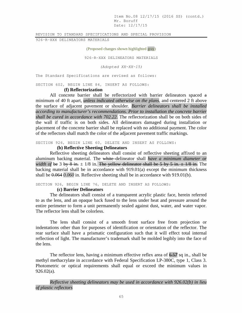
Item No.08 12/17/15 (2016 SS) (contd.) Mr. Boruff Date: 12/17/15 REVISION TO STANDARD SPECIFICATIONS AND SPECIAL PROVISION 926-R-XXX DELINEATORS MATERIALS
65
(Proposed changes shown highlighted gray)
926-R-XXX DELINEATORS MATERIALS
(Adopted XX-XX-15)
The Standard Specifications are revised as follows: SECTION 602, BEGIN LINE 84, INSERT AS FOLLOWS: (f) Reflectorization All concrete barrier shall be reflectorized with barrier delineators spaced a minimum of 40 ft apart, unless indicated otherwise on the plans, and centered 2 ft above the surface of adjacent pavement or shoulder. Barrier delineators shall be installed according to manufacturer’s recommendations. Prior to installation the concrete barrier shall be cured in accordance with 702.22. The reflectorization shall be on both sides of the wall if traffic is on both sides. All delineators damaged during installation or placement of the concrete barrier shall be replaced with no additional payment. The color of the reflectors shall match the color of the adjacent pavement traffic markings. SECTION 926, BEGIN LINE 60, DELETE AND INSERT AS FOLLOWS: (b) Reflective Sheeting Delineators Reflective sheeting delineators shall consist of reflective sheeting affixed to an aluminum backing material. The white delineator shall have a minimum diameter or width of be 3 by 8 in. ± 1/8 in. The yellow delineator shall be 5 by 5 in. ± 1/8 in. The backing material shall be in accordance with 919.01(a) except the minimum thickness shall be 0.064 0.060 in. Reflective sheeting shall be in accordance with 919.01(b). SECTION 926, BEGIN LINE 76, DELETE AND INSERT AS FOLLOWS: (c) Barrier Delineators The delineators shall consist of a transparent acrylic plastic face, herein referred to as the lens, and an opaque back fused to the lens under heat and pressure around the entire perimeter to form a unit permanently sealed against dust, water, and water vapor. The reflector lens shall be colorless. The lens shall consist of a smooth front surface free from projection or indentations other than for purposes of identification or orientation of the reflector. The rear surface shall have a prismatic configuration such that it will effect total internal reflection of light. The manufacturer’s trademark shall be molded legibly into the face of the lens. The reflector lens, having a minimum effective reflex area of 6.57 sq in., shall be methyl methacrylate in accordance with Federal Specification LP-380C, type 1, Class 3. Photometric or optical requirements shall equal or exceed the minimum values in 926.02(a). Reflective sheeting delineators may be used in accordance with 926.02(b) in lieu of plastic reflectors

Item No.08 12/17/15 (2016 SS) (contd.) Mr. Boruff Date: 12/17/15 REVISION TO STANDARD SPECIFICATIONS AND SPECIAL PROVISION 926-R-XXX DELINEATORS MATERIALS
66
SECTION 926, BEGIN LINE 102, INSERT AS FOLLOWS: (d) Temporary Barrier Delineator Temporary barrier delineators shall consist of a type III or higher sheeting in accordance with 919.01(b)1 affixed to a reboundable substrate. The delineator shall be 8 by 12 in. vertically mounted. The mounting bracket used to affix the delineator to the barrier shall not be more than 3 in. vertical; alternatively the reflector may be mounted directly to the barrier surface.

Item No.08 12/17/15 (2016 SS) (contd.) Mr. Boruff Date: 12/17/15 COMMENTS AND ACTION 926-R-XXX DELINEATORS MATERIALS
67
DISCUSSION:
Motion: Second: Ayes: Nays: FHWA Approval:
Action: Passed as Submitted Passed as Revised __ __ Withdrawn
Standard Specifications Sections referenced and/or affected: 602.04 pg 402; 926.02 pg 1083 and
1084. Recurring Special Provision affected:
NONE Standard Drawing affected:
NONE Design Manual Sections affected:
NONE GIFE Sections cross-references:
NONE
2018 Standard Specifications Revise Pay Items List Create RSP (No. ) Effective Letting RSP Sunset Date: Revise RSP (No. ) Effective Letting RSP Sunset Date: Standard Drawing Effective Create RPD (No. ) Effective Letting GIFE Update

Mr. Beeson Date: 12/17/15
STANDARD SPECIFICATIONS, SPECIAL PROVISIONS AND STANDARD DRAWINGS REVISION TO STANDARD SPECIFICATIONS
68
PROPOSAL TO STANDARDS COMMITTEE PROBLEM(S) ENCOUNTERED: These revisions were the outcome of a conflict resolution meeting regarding a warranty claim for RS-34344 (US-35) in LaPorte District. The observed pavement distress of rutting, in addition to raveling and delamination, was determined to be attributable to shortcomings in the 411 specification. PROPOSED SOLUTION: Include additional mix-design criteria as recommended by the International Slurry Surfacing Association. APPLICABLE STANDARD SPECIFICATIONS: 411 APPLICABLE STANDARD DRAWINGS: N/A APPLICABLE DESIGN MANUAL SECTION: 304-19.0 APPLICABLE SECTION OF GIFE: N/A APPLICABLE RECURRING SPECIAL PROVISIONS: N/A PAY ITEMS AFFECTED: as per 411 APPLICABLE SUB-COMMITTEE ENDORSEMENT: Michael Prather, Scott Chandler (Crawfordsville Pavement Engineer) and Larry Galehouse (Director for the National Center for Pavement Preservation). IMPACT ANALYSIS (attach report): attached Submitted By: Matt Beeson Title: State Materials Engineer Organization: Office of Materials Management Phone Number: 317-610-7251x204

Mr. Beeson Date: 12/17/15
STANDARD SPECIFICATIONS, SPECIAL PROVISIONS AND STANDARD DRAWINGS REVISION TO STANDARD SPECIFICATIONS
69
IMPACT ANALYSIS REPORT CHECKLIST
Explain the business case as to why this item should be presented to the Standards Committee for approval. Answer the following questions with Yes, No or N/A. Does this item appear in any other specification sections? No Will approval of this item affect the Approved Materials List? No Will this proposal improve: Construction costs? No
Construction time? No
Customer satisfaction? Possibly
Congestion/travel time? No
Ride quality? Yes
Will this proposal reduce operational costs or maintenance effort? Yes Will this item improve safety:
For motorists? Possibly
For construction workers? No Will this proposal improve quality for:
Construction procedures/processes? Yes
Asset preservation? Yes
Design process? No
Will this change provide the contractor more flexibility? No Will this proposal provide clarification for the Contractor and field personnel? Possibly Can this item improve/reduce the number of potential change orders? Yes Is this proposal needed for compliance with:
Federal or State regulations? No
AASHTO or other design code? No
Is this item editorial? No Provide any further information as to why this proposal should be placed on the Standards Committee meeting Agenda:

Item No.09 12/17/15 (2016 SS) (contd.) Mr. Beeson Date: 12/17/15 REVISION TO STANDARD SPECIFICATIONS SECTION 411 – WARRANTED MICRO-SURFACING 411.03 DESIGN MIX FORMULA 411.06 PREPARATION OF SURFACES
70
SECTION 411, BEGIN LINE 60, DELETE AND INSERT AS FOLLOWS: (i) results for the tests in the following:
Characteristic Test Method ISSA* Requirement Wet Cohesion 30 minutes, min. (set time) 60 minutes, min. (traffic)
TB-139**
12 kg-cm 20 kg-cm
Wet Stripping, min. Integrity SB
TB-114 TB-144
> 90% 11 pts min.
Wet Track Abrasion Loss 60 minutes soak, max. 6 day soak, max.
TB-100
536538 g/sq m 807 g/sq m
Saturated Abrasion Compatibility, max. TB-144 3g loss
Mix Time @ 77°F (25°C) TB-113** controllable to 120 s Mix Time @ 104°F (40°C) TB-113** controllable to 35 s Excess Binder TB-109 538 g/sq m Deformation, max. TB-147 5% * International Slurry Surfacing Association ** The TB-139 (set time) and TB-113 (mix time) tests shall be checked at the highest
temperature expected during construction. For the TB-113 test at 104°F (40°C), all ingredients and containers shall be preheated.
SECTION 411, BEGIN LINE 86, INSERT AS FOLLOWS: 411.06 Preparation of Surfaces The Contractor shall be responsible for all surface preparation necessary to meet the performance requirements for warranted micro-surfacing. All castings and detector housings shall be protected prior to the application of material in accordance with 404.07, except that raised pavement markers shall be removed. Any existing thermoplastic pavement markings shall be removed prior to placement of warranted micro-surfacing. Cracks in the pavement in excess of 1/4 in. shall be filled in accordance with 408 prior to placement of warranted micro-surfacing. The pavement surface shall have tack coat applied in accordance with 406 prior to placement of warranted micro-surfacing.

Item No.09 12/17/15 (2016 SS) (contd.) Mr. Beeson Date: 12/17/15 COMMENTS AND ACTION 411.03 DESIGN MIX FORMULA 411.06 PREPARATION OF SURFACES
71
DISCUSSION:
Motion: Second: Ayes: Nays: FHWA Approval:
Action: Passed as Submitted Passed as Revised __ __ Withdrawn
Standard Specifications Sections referenced and/or affected:
411.03 pg 317; 411.06 pg 317. Recurring Special Provision affected:
NONE Standard Drawing affected:
NONE Design Manual Sections affected:
304-19.0 GIFE Sections cross-references:
NONE
2018 Standard Specifications Revise Pay Items List Create RSP (No. ) Effective Letting RSP Sunset Date: Revise RSP (No. ) Effective Letting RSP Sunset Date: Standard Drawing Effective Create RPD (No. ) Effective Letting GIFE Update