10.1 chapter 10 error detection and correction copyright © the mcgraw-hill companies, inc....
Post on 22-Dec-2015
213 views
TRANSCRIPT

10.1
Chapter 10
Error Detection and
Correction
Copyright © The McGraw-Hill Companies, Inc. Permission required for reproduction or display.

10.2
Data can be corrupted during transmission.
Some applications require that errors be detected and corrected.
Note

10.3
10-1 INTRODUCTION10-1 INTRODUCTION
Let us first discuss some issues related, directly or Let us first discuss some issues related, directly or indirectly, to error detection and correction.indirectly, to error detection and correction.
Types of ErrorsRedundancyDetection Versus CorrectionForward Error Correction Versus RetransmissionCodingModular Arithmetic
Topics discussed in this section:Topics discussed in this section:

10.4
In a single-bit error, only 1 bit in the data unit has changed.
Note

10.5
Figure 10.1 Single-bit error

10.6
A burst error means that 2 or more bits in the data unit have changed.
Note

10.7
Figure 10.2 Burst error of length 8

10.8
To detect or correct errors, we need to send extra (redundant) bits with data.
Note

10.9
Figure 10.3 The structure of encoder and decoder

10.10
In this book, we concentrate on block codes; we leave convolution codes
to advanced texts.
Note
10.11
In modulo-N arithmetic, we use only the integers in the range 0 to N −1, inclusive.
Note

10.12
Figure 10.4 XORing of two single bits or two words

10.13
10-2 BLOCK CODING10-2 BLOCK CODING
In block coding, we divide our message into blocks, In block coding, we divide our message into blocks, each of k bits, called each of k bits, called datawordsdatawords. We add r redundant . We add r redundant bits to each block to make the length n = k + r. The bits to each block to make the length n = k + r. The resulting n-bit blocks are called resulting n-bit blocks are called codewordscodewords..
Error DetectionError CorrectionHamming DistanceMinimum Hamming Distance
Topics discussed in this section:Topics discussed in this section:

10.14
Figure 10.5 Datawords and codewords in block coding ( n = k+r), r: extra bits

10.15
Figure 10.6 Process of error detection in block coding

10.16
Let us assume that k = 2 and n = 3. Table 10.1 shows the list of datawords and codewords. Later, we will see how to derive a codeword from a dataword.
Assume the sender encodes the dataword 01 as 011 andsends it to the receiver. Consider the following cases:
1. The receiver receives 011. It is a valid codeword. The receiver extracts the dataword 01 from it.
Example 10.2

10.17
2. The codeword is corrupted during transmission, and 111 is received. This is not a valid codeword and is discarded.
3. The codeword is corrupted during transmission, and 000 is received. This is a valid codeword. The receiver incorrectly extracts the dataword 00. Two corrupted bits have made the error undetectable.
Example 10.2 (continued)

10.18
Table 10.1 A code for error detection (Example 10.2)

10.19
An error-detecting code can detect only the types of errors for which it is designed; other types of errors may
remain undetected.
Note
10.20
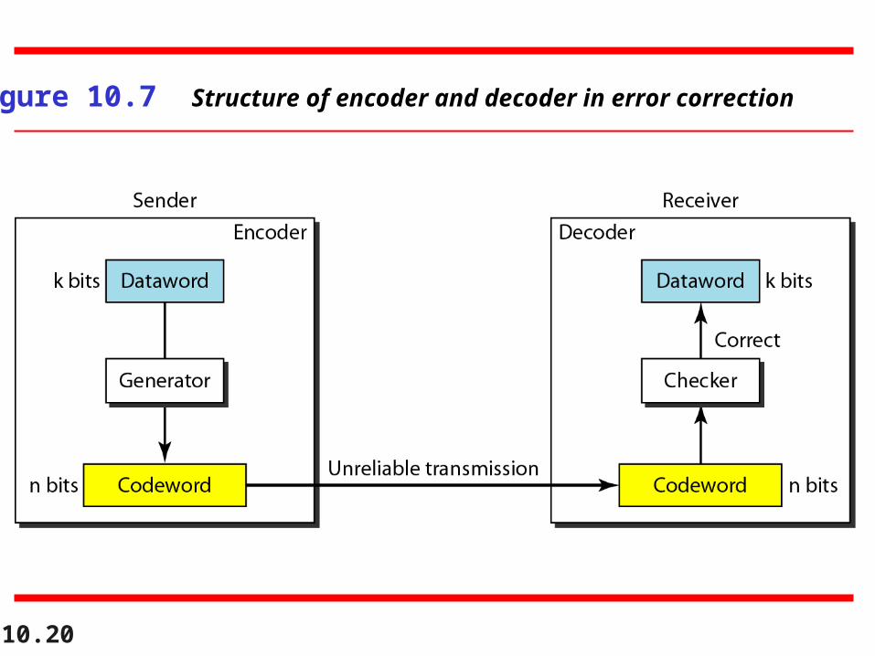
Figure 10.7 Structure of encoder and decoder in error correction

10.21
Let us add more redundant bits to Example 10.2 to see if the receiver can correct an error without knowing what was actually sent. We add 3 redundant bits to the 2-bit dataword to make 5-bit codewords. Table 10.2 shows the datawords and codewords. Assume the dataword is 01. The sender creates the codeword 01011. The codeword is corrupted during transmission, and 01001 is received. First, the receiver finds that the received codeword is not in the table. This means an error has occurred. The receiver, assuming that there is only 1 bit corrupted, uses the following strategy to guess the correct dataword.
Example 10.3

10.22
1. Comparing the received codeword with the first codeword in the table (01001 versus 00000), the receiver decides that the first codeword is not the one that was sent because there are two different bits.
2. By the same reasoning, the original codeword cannot be the third or fourth one in the table.
3. The original codeword must be the second one in the table because this is the only one that differs from the received codeword by 1 bit. The receiver replaces 01001 with 01011 and consults the table to find the dataword 01.
Example 10.3 (continued)

10.23
Table 10.2 A code for error correction (Example 10.3)

10.24
The Hamming distance between two words is the number of differences
between corresponding bits.
Note
10.25
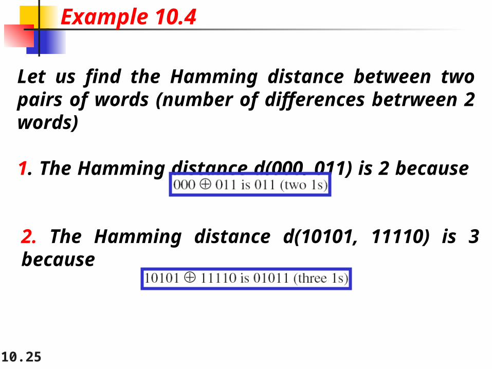
Let us find the Hamming distance between two pairs of words (number of differences betrween 2 words)
1. The Hamming distance d(000, 011) is 2 because
Example 10.4
2. The Hamming distance d(10101, 11110) is 3 because
10.26
The minimum Hamming distance is the smallest Hamming distance between all possible pairs in a set of words.
Note

10.27
Find the minimum Hamming distance of the coding scheme in Table 10.1.
SolutionWe first find all Hamming distances.
Example 10.5
The dmin in this case is 2.

10.28
Find the minimum Hamming distance of the coding scheme in Table 10.2.
SolutionWe first find all the Hamming distances.
The dmin in this case is 3.
Example 10.6

10.29
To guarantee the detection of up to s errors in all cases, the minimum
Hamming distance in a block code must be dmin = s + 1.
Note

10.30
The minimum Hamming distance for our first code scheme (Table 10.1) is 2. This code guarantees detection of only a single error. For example, if the third codeword (101) is sent and one error occurs, the received codeword does not match any valid codeword. If two errors occur, however, the received codeword may match a valid codeword and the errors are not detected.
Example 10.7

10.31
Our second block code scheme (Table 10.2) has dmin = 3. This code can detect up to two errors. Again, we see that when any of the valid codewords is sent, two errors create a codeword which is not in the table of valid codewords. The receiver cannot be fooled.
However, some combinations of three errors change a valid codeword to another valid codeword. The receiver accepts the received codeword and the errors are undetected.
Example 10.8
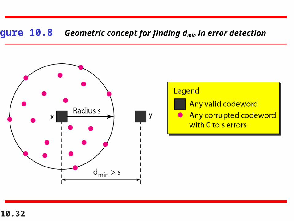
10.32
Figure 10.8 Geometric concept for finding dmin in error detection

10.33
Figure 10.9 Geometric concept for finding dmin in error correction

10.34
To guarantee correction of up to t errors in all cases, the minimum Hamming
distance in a block code must be dmin = 2t + 1.
Note
10.35
A code scheme has a Hamming distance dmin = 4. What is the error detection and correction capability of this scheme?
SolutionThis code guarantees the detection of up to three errors(s = 3), but it can correct up to one error. In other words, if this code is used for error correction, part of its capability is wasted. Error correction codes need to have an odd minimum distance (3, 5, 7, . . . ).
Example 10.9

10.36
10-3 LINEAR BLOCK CODES10-3 LINEAR BLOCK CODES
Almost all block codes used today belong to a subset Almost all block codes used today belong to a subset called called linear block codeslinear block codes. A linear block code is a code . A linear block code is a code in which the exclusive OR (addition modulo-2) of two in which the exclusive OR (addition modulo-2) of two valid codewords creates another valid codeword.valid codewords creates another valid codeword.
Minimum Distance for Linear Block CodesSome Linear Block Codes
Topics discussed in this section:Topics discussed in this section:

10.37
In a linear block code, the exclusive OR (XOR) of any two valid codewords creates another valid codeword.
Note

10.38
Let us see if the two codes we defined in Table 10.1 and Table 10.2 belong to the class of linear block codes.
1. The scheme in Table 10.1 is a linear block code because the result of XORing any codeword with any other codeword is a valid codeword. For example, the XORing of the second and third codewords creates the fourth one.
2. The scheme in Table 10.2 is also a linear block code. We can create all four codewords by XORing two other codewords.
Example 10.10

10.39
In our first code (Table 10.1), the numbers of 1s in the nonzero codewords are 2, 2, and 2. So the minimum Hamming distance is dmin = 2. In our second code (Table 10.2), the numbers of 1s in the nonzero codewords are 3, 3, and 4. So in this code we have dmin = 3.
Example 10.11

10.40
A simple parity-check code is a single-bit error-detecting
code in which n = k + 1 with dmin = 2.
The extra-bit: parity bits is selected to make the total number of 1s in the
codeword even ( even parity) or odd (for odd parity)

10.41
Table 10.3 Simple parity-check code C(5, 4)

10.42
Figure 10.10 Encoder and decoder for simple parity-check code

10.43
A simple parity-check code can detect an odd number of errors.
Note

10.44
All Hamming codes discussed in this book have dmin = 3.
The relationship between m and n in these codes is n = 2m − 1.
Note

10.45
Figure 10.11 Two-dimensional parity-check code

10.46
Figure 10.11 Two-dimensional parity-check code

10.47
Figure 10.11 Two-dimensional parity-check code

10.48
Table 10.4 Hamming code C(7, 4)

10.49
Figure 10.12 The structure of the encoder and decoder for a Hamming code

10.50
10-4 CYCLIC CODES10-4 CYCLIC CODES
Cyclic codesCyclic codes are special linear block codes with one are special linear block codes with one extra property. In a cyclic code, if a codeword is extra property. In a cyclic code, if a codeword is cyclically shifted (rotated), the result is another cyclically shifted (rotated), the result is another codeword.codeword.
Cyclic Redundancy CheckHardware ImplementationPolynomialsCyclic Code AnalysisAdvantages of Cyclic CodesOther Cyclic Codes
Topics discussed in this section:Topics discussed in this section:

10.51
Table 10.6 A CRC code with C(7, 4)

10.52
Figure 10.14 CRC encoder and decoder

10.53
Figure 10.15 Division in CRC encoder
The division is done to have the most left bit 0, and is done from left to right like a regular division. The division is done until the quotient has as many bits as the dividend. The new codeword is the dataword extended by the remainder.
The divisor (generator) is agreed upon.

10.54
To recover the dataword, we divide the same way. In the following slide, we show an example where the codeword was changed (1 bit error) from 1001110 to 1000110. We see that there will be a remainder (syndrome)

10.55
Figure 10.16 Division in the CRC decoder for two cases

10.56
The divisor in a cyclic code is normally called the generator polynomial
or simply the generator.
Note

10.57
Advantages:
Very good performance in detecting single-bit errors, double errors, an odd number of errors and burst errors.
Easy to implement

10.58
10-5 CHECKSUM10-5 CHECKSUMThe last error detection method we discuss here is The last error detection method we discuss here is called the checksum. The checksum is used in the called the checksum. The checksum is used in the Internet by several protocols although not at the data Internet by several protocols although not at the data link layer. However, we briefly discuss it here.link layer. However, we briefly discuss it here.The idea is to simply send an additional data ( for The idea is to simply send an additional data ( for example the sum) along with the data. At the example the sum) along with the data. At the destination, the sum is calculated and compared to the destination, the sum is calculated and compared to the one sent.one sent.
One’s ComplementInternet Checksum
Topics discussed in this section:Topics discussed in this section:

10.59
Suppose our data is a list of five 4-bit numbers that we want to send to a destination. In addition to sending these numbers, we send the sum of the numbers. For example, if the set of numbers is (7, 11, 12, 0, 6), we send (7, 11, 12, 0, 6, 36), where 36 is the sum of the original numbers. The receiver adds the five numbers and compares the result with the sum. If the two are the same, the receiver assumes no error, accepts the five numbers, and discards the sum. Otherwise, there is an error somewhere and the data are not accepted.
Example 10.18

10.60
We can make the job of the receiver easier if we send the negative (complement) of the sum, called the checksum. In this case, we send (7, 11, 12, 0, 6, −36). The receiver can add all the numbers received (including the checksum). If the result is 0, it assumes no error; otherwise, there is an error.
Example 10.19

10.61
How can we represent the number 21 in one’s complement arithmetic using only four bits?
SolutionThe number 21 in binary is 10101 (it needs five bits). We can wrap the leftmost bit and add it to the four rightmost bits. We have (0101 + 1) = 0110 or 6.
Example 10.20
10.62
How can we represent the number −6 in one’s complement arithmetic using only four bits?
SolutionIn one’s complement arithmetic, the negative or complement of a number is found by inverting all bits. Positive 6 is 0110; negative 6 is 1001. If we consider only unsigned numbers, this is 9. In other words, the complement of 6 is 9. Another way to find the complement of a number in one’s complement arithmetic is to subtract the number from 2n − 1 (16 − 1 in this case).
Example 10.21

10.63
Let us redo Exercise 10.19 using one’s complement arithmetic. Figure 10.24 shows the process at the sender and at the receiver. The sender initializes the checksum to 0 and adds all data items and the checksum (the checksum is considered as one data item and is shown in color). The result is 36. However, 36 cannot be expressed in 4 bits. The extra two bits are wrapped and added with the sum to create the wrapped sum value 6. In the figure, we have shown the details in binary. The sum is then complemented, resulting in the checksum value 9 (15 − 6 = 9). The sender now sends six data items to the receiver including the checksum 9.
Example 10.22
10.64
The receiver follows the same procedure as the sender. It adds all data items (including the checksum); the result is 45. The sum is wrapped and becomes 15. The wrapped sum is complemented and becomes 0. Since the value of the checksum is 0, this means that the data is not corrupted. The receiver drops the checksum and keeps the other data items. If the checksum is not zero, the entire packet is dropped.
Example 10.22 (continued)

10.65
Figure 10.24 Example 10.22

10.66
Internet Checksum
Using a 16-bit checksum calculated the following way

10.67
Sender site:1. The message is divided into 16-bit words.2. The value of the checksum word is set to 0.3. All words including the checksum are added using one’s complement addition.4. The sum is complemented and becomes the checksum.5. The checksum is sent with the data.
Note

10.68
Receiver site:1. The message (including checksum) is divided into 16-bit words.2. All words are added using one’s complement addition.3. The sum is complemented and becomes the new checksum.4. If the value of checksum is 0, the message is accepted; otherwise, it is rejected.
Note

10.69
Let us calculate the checksum for a text of 8 characters (“Forouzan”). The text needs to be divided into 2-byte (16-bit) words. We use ASCII (see Appendix A) to change each byte to a 2-digit hexadecimal number. For example, F is represented as 0x46 and o is represented as 0x6F. Figure 10.25 shows how the checksum is calculated at the sender and receiver sites. In part a of the figure, the value of partial sum for the first column is 0x36. We keep the rightmost digit (6) and insert the leftmost digit (3) as the carry in the second column. The process is repeated for each column. Note that if there is any corruption, the checksum recalculated by the receiver is not all 0s. We leave this an exercise.
Example 10.23

10.70
Figure 10.25 Example 10.23