10.1. show ip route - mct expertmctexpert.net/wp-content/uploads/2016/03/10-troubleshooting... ·...
TRANSCRIPT

10.1. Show IP Route
When troubleshooting routing problems, one of the first steps might be to use ping or traceroute to check communication with a host on the destination network. If ping or traceroute fails, use the show ip route command to verify that the router has a route to the destination network. The following table lists things to check when troubleshooting missing routing information.
Problem Description
Missing connected route
A route to every directly‐connected network should appear in the routing table. If a directly‐connected network is missing, check the following:
Verify the operational status of the interface. Make sure that the interface has not been shut down, and that you have Layer 1 and Layer 2 connectivity.
Verify the TCP/IP configuration for the interface. The interface must be assigned an IP address before its network will show in the routing table.
Missing static route
Static routes appear in the routing table only if the interface used to reach the next hop router is up and has been assigned an IP address. If a static route is missing:
Verify that the interface used to reach the next hop router has an entry as a directly‐connected network.
Verify that the static route was configured properly (with the correct out interface or with a next hop router that is on the same subnet as an interface that is up).
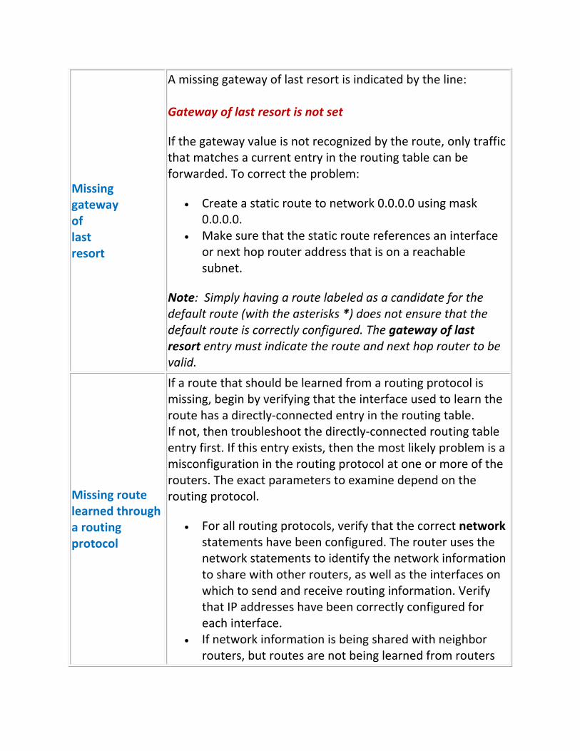
Missing gateway of last resort
A missing gateway of last resort is indicated by the line: Gateway of last resort is not set
If the gateway value is not recognized by the route, only traffic that matches a current entry in the routing table can be forwarded. To correct the problem:
Create a static route to network 0.0.0.0 using mask 0.0.0.0.
Make sure that the static route references an interface or next hop router address that is on a reachable subnet.
Note: Simply having a route labeled as a candidate for the default route (with the asterisks *) does not ensure that the default route is correctly configured. The gateway of last resort entry must indicate the route and next hop router to be valid.
Missing route learned through a routing protocol
If a route that should be learned from a routing protocol is missing, begin by verifying that the interface used to learn the route has a directly‐connected entry in the routing table. If not, then troubleshoot the directly‐connected routing table entry first. If this entry exists, then the most likely problem is a misconfiguration in the routing protocol at one or more of the routers. The exact parameters to examine depend on the routing protocol.
For all routing protocols, verify that the correct network statements have been configured. The router uses the network statements to identify the network information to share with other routers, as well as the interfaces on which to send and receive routing information. Verify that IP addresses have been correctly configured for each interface.
If network information is being shared with neighbor routers, but routes are not being learned from routers

accessible on that interface, check for a passive‐interface statement. This configuration prevents routing updates from being sent or received on that interface.
For RIP, verify that all routers are using the correct version. A missing version statement indicates that the router is using version 1.
For OSPF, make sure that the network statements on each router use the same area number. The process ID for the router section does not have to match between routers.
For OSPF, make sure that the same hello and dead timer intervals are used. Hello intervals do not need to match on EIGRP routers.
For EIGRP, make sure that the AS number for the router eigrp section matches on both routers.
If specific routes have been replaced by summarized routes on RIP or EIGRP, remove the auto‐summary entry to prevent automatic summarization.
For EIGRP and OSPF, verify that authentication settings match on all routers.
If multiple routing protocols are being used, be aware that the route with the lowest administrative distance will be used. This means that an EIGRP route might replace a RIP or OSPF route.
© Sergey Gorokhod MCT/MCSE/MCITP/MCTS/MCSA/CCSE/CCSA/CCNA/A+® E‐mail: [email protected] Mob: (+972) 526848757
10.2. Show IP Protocols
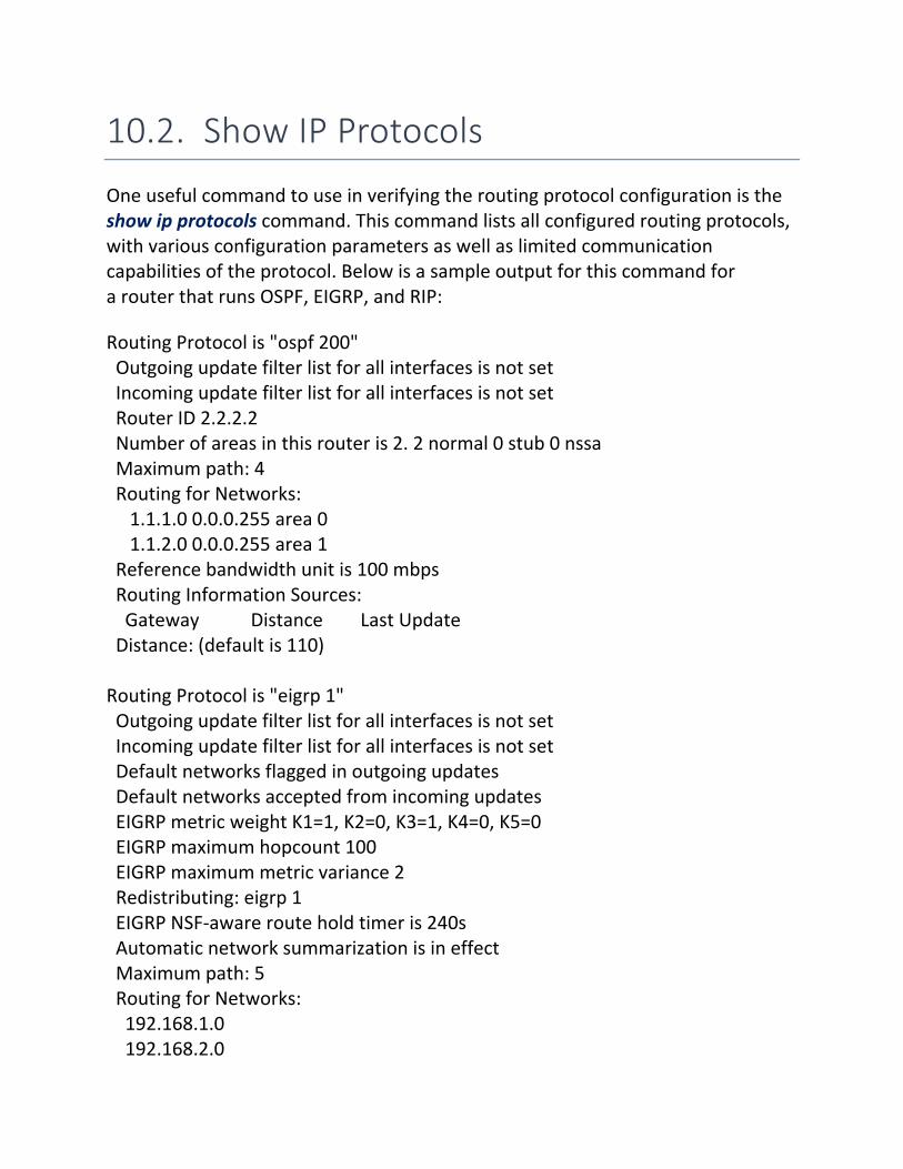
One useful command to use in verifying the routing protocol configuration is the show ip protocols command. This command lists all configured routing protocols, with various configuration parameters as well as limited communication capabilities of the protocol. Below is a sample output for this command for a router that runs OSPF, EIGRP, and RIP:
Routing Protocol is "ospf 200" Outgoing update filter list for all interfaces is not set Incoming update filter list for all interfaces is not set Router ID 2.2.2.2 Number of areas in this router is 2. 2 normal 0 stub 0 nssa Maximum path: 4 Routing for Networks: 1.1.1.0 0.0.0.255 area 0 1.1.2.0 0.0.0.255 area 1 Reference bandwidth unit is 100 mbps Routing Information Sources: Gateway Distance Last Update Distance: (default is 110) Routing Protocol is "eigrp 1" Outgoing update filter list for all interfaces is not set Incoming update filter list for all interfaces is not set Default networks flagged in outgoing updates Default networks accepted from incoming updates EIGRP metric weight K1=1, K2=0, K3=1, K4=0, K5=0 EIGRP maximum hopcount 100 EIGRP maximum metric variance 2 Redistributing: eigrp 1 EIGRP NSF‐aware route hold timer is 240s Automatic network summarization is in effect Maximum path: 5 Routing for Networks: 192.168.1.0 192.168.2.0

192.168.3.0 Passive Interface(s): FastEthernet0/1 Routing Information Sources: Gateway Distance Last Update 192.168.1.12 90 00:55:50 192.168.2.15 90 00:55:50 Distance: internal 90 external 170 Routing Protocol is "rip" Outgoing update filter list for all interfaces is not set Incoming update filter list for all interfaces is not set Sending updates every 30 seconds, next due in 0 seconds Invalid after 180 seconds, hold down 180, flushed after 240 Redistributing: rip Default version control: send version 1, receive any version Automatic network summarization is not in effect Maximum path: 4 Routing for Networks: 2.0.0.0 Routing Information Sources: Gateway Distance Last Update Distance: (default is 120)
Entry Description
Routing Protocol
The command will show each routing process running on the router as a separate section.
For OSPF, the entry includes the process ID defined with the router ospf command.
For EIGRP, the entry includes the autonomous system number defined with the router eigrp command.
You might have multiple OSPF or EIGRP sections if you have defined multiple processes or AS numbers. All RIP information is in a single section.

Maximum path
The maximum path entry identifies the maximum number of paths that can be used for load balancing.
For RIP and OSPF, these are equal‐cost routes. For EIGRP, the paths are equal‐cost if the EIGRP
maximum metric variance value is 1. They are unequal‐cost routes if this value is greater than 1.
Routing for Networks
The Routing for Networks section corresponds to the network statements in the router section of the configuration file. This section shows the same information that you can view using show running‐config.
For RIP, these will be the classful network addresses. For OSPF, the network statements include the wildcard
mask and the area number. For EIGRP, the networks might be classful networks or
include a wildcard mask.
Routing Information Sources
The Routing Information Sources section identifies neighbor routers. Each line indicates a different neighbor router that is connected to the same subnet as one of the router's interfaces. If this section is blank, this means that the router has not been able to communicate with other routers, and will therefore not learn routes from any other router.
Automatic network summarization
For RIP and EIGRP, the Automatic network summarizationline indicates the presence of the auto‐summary parameter in the configuration file.
Passive Interfaces
The Passive Interface(s) section lists the interfaces that are excluded from sending and receiving routing updates. Interfaces in this section correspond to the passive‐interface entries in the configuration file.

Additional information
Additional information depends on the routing protocol:
For OSPF, you can view the current router ID and the number of areas.
For RIP, you can view update intervals and the RIP version in use (see the Default version control line).
For EIGRP, you can view the variance setting and the K values.
© Sergey Gorokhod MCT/MCSE/MCITP/MCTS/MCSA/CCSE/CCSA/CCNA/A+® E‐mail: [email protected] Mob: (+972) 526848757
10.3. Route Summarization Issues
When troubleshooting routing protocols, you might have cases where the routing table does not look as expected due to route summarization issues. Be aware of the following facts regarding automatic route summarization:
Automatic route summarization is supported on RIP version 2 and EIGRP; it is not supported on OSPF.
To enable automatic summarization, add the auto‐summary parameter to the router section. For example, the following enabled automatic summarization for EIGRP autonomous system 300: router eigrp 300 auto‐summary
Use the no auto‐summary command to disable automatic summarization. When disabled, all routes that match a network entry will be advertised with the configured subnet mask.
Auto‐summarization summarizes routes along classful network boundaries. For example:
o 192.168.2.64/27 and 192.168.2.96/27 will be summarized as 192.168.2.0/24.
o 172.16.1.0/24 and 172.16.2.0/24 will be summarized as 172.16.0.0/16.
o 10.1.1.0/24 and 10.5.0.0/16 will be summarized as 10.0.0.0/8. The router will only use automatic summarization when advertising routes
on interfaces that are in different classful networks from the summarized route. For example consider a router with the following interfaces:
o Fa0/0 = 10.0.1.0/24 o Fa0/1 = 10.0.2.0/24 o Ser0/1/0 = 10.0.3.0/24 o Ser0/1/1 = 192.168.12.0/24
When routes are advertised with a neighbor router connected to the Ser0/1/0 interface, the 10.0.1.0/24 and 10.0.2.0/24 routes are not summarized. This is because the Ser0/1/0 interface is in the same classful network as the Fa0/0 and Fa0/1 interfaces. When advertising routes to a neighbor on Ser0/1/1, all other routes will be summarized as 10.0.0.0/8.

To summarize routes within classful network boundaries, or to use summarization with OSPF, you must use manual summarization.
The network entries for a router section do not effect summarization; they only effect the following:
o Which interfaces will participate in the routing protocol. o Which routes will be shared by the routing protocol.
Having a network statement that matches multiple interfaces does not mean that those routes will be summarized. Instead, it simply means that the single network statement has been used to enable the routing protocol on multiple interfaces.
When using multiple routing protocols to share routes about the same networks, you might lose specific routes if those routes are included in summarized routes and if the source of the routing information is preferred.
© Sergey Gorokhod MCT/MCSE/MCITP/MCTS/MCSA/CCSE/CCSA/CCNA/A+® E‐mail: [email protected] Mob: (+972) 526848757

10.4. RIP Debugging 1
You should be familiar with the RIP routing update sequences and messages. From the output of a debug ip rip command, you should be able to identify the consequences of the various messages. Listed below is sample output from the debug ip rip command.
1 RIP: received v2 update from 192.168.1.1 on Ethernet0 2 10.0.0.0/8 via 0.0.0.0 in 1 hops 3 192.168.5.0/24 via 0.0.0.0 in 15 hops 4 RIP: sending v2 update to 224.0.0.9 via Serial0 (192.168.2.201) 5 network 10.0.0.0/8 via 0.0.0.0, metric 2, tag 0 6 network 192.168.1.0/24 via 0.0.0.0, metric 1, tag 0 7 network 192.168.5.0/24 via 0.0.0.0 in 16 hops (inaccessible) 8 RIP: received v2 update from 192.168.2.202 on Serial0 9 192.168.3.0/24 via 0.0.0.0 in 1 hops 10 192.168.4.0/24 via 0.0.0.0 in 2 hops 11 RIP: sending v2 update to 224.0.0.9 via Ethernet0 (192.168.1.201) 12 network 192.168.2.0/24 via 0.0.0.0, metric 1, tag 0 13 network 192.168.3.0/24 via 0.0.0.0, metric 2, tag 0 14 network 192.168.4.0/24 via 0.0.0.0, metric 3, tag 0
The following table interprets each line in the sample output.
Line Number(s)
Meaning
1, 8
This line identifies the router and the interface where RIP updates are received. In this example, the router is connected to two other routers:
Router 192.168.1.1 on Ethernet0 Router 192.168.2.202 on Serial0

2‐3, 9‐10
Indented below each RIP line are the specific routing entries that are received. This example shows the following routes received:
10.0.0.0 and 192.168.5.0 from router 192.168.1.1 on Etherent0
192.168.3.0 and 192.168.4.0 from router 192.168.2.202 on Serial0
The hop count shown in the received route will be the metric used when the route is placed in the routing table of the local router.
4, 11
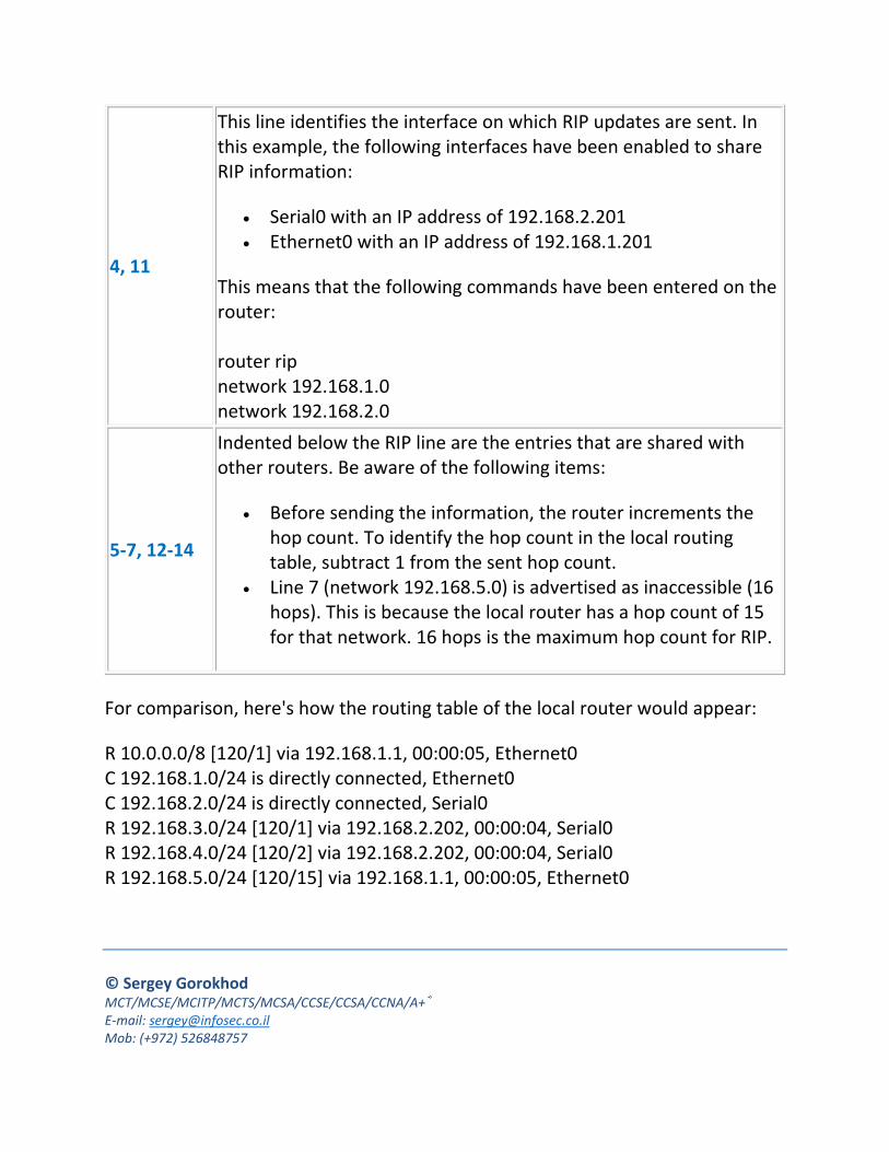
This line identifies the interface on which RIP updates are sent. In this example, the following interfaces have been enabled to share RIP information:
Serial0 with an IP address of 192.168.2.201 Ethernet0 with an IP address of 192.168.1.201
This means that the following commands have been entered on the router: router rip network 192.168.1.0 network 192.168.2.0 Notice that updates for version 2 are sent to the multicast address of 224.0.0.9.
5‐7, 12‐14
Indented below the RIP line are the entries that are shared with other routers. Be aware of the following items:
Before sending the information, the router increments the hop count. To identify the hop count in the local routing table, subtract 1 from the sent hop count.
Line 7 (network 192.168.5.0) is advertised as inaccessible (16 hops). This is because the local router has a hop count of 15 for that network. 16 hops is the maximum hop count for RIP.
For comparison, here's how the routing table of the local router would appear:

R 10.0.0.0/8 [120/1] via 192.168.1.1, 00:00:05, Ethernet0 C 192.168.1.0/24 is directly connected, Ethernet0 C 192.168.2.0/24 is directly connected, Serial0 R 192.168.3.0/24 [120/1] via 192.168.2.202, 00:00:04, Serial0 R 192.168.4.0/24 [120/2] via 192.168.2.202, 00:00:04, Serial0 R 192.168.5.0/24 [120/15] via 192.168.1.1, 00:00:05, Ethernet0
Common problems indicated by RIP debugging include:
Inaccessible routes Mismatched RIP versions (one router using version 1, with another router
using version 2) Routes not being advertised as expected (caused by missing network
statements)
© Sergey Gorokhod MCT/MCSE/MCITP/MCTS/MCSA/CCSE/CCSA/CCNA/A+® E‐mail: [email protected] Mob: (+972) 526848757

10.5. RIP Troubleshooting Introduction
The next set of labs give you a chance to troubleshoot RIP routing. All labs use the same network layout as shown.
Subnets are assigned addresses as follows:
Router Interface Subnet
R1
Fa0/0 192.168.1.0/25
Fa0/1 192.168.1.128/25
S0/1/1 172.17.0.0/30
R2
S0/1/0 172.17.0.0/30
Fa0/0 192.168.2.0/26
Fa0/1 192.168.2.128/26
S0/1/1 172.18.0.64/30
R3
S0/1/0 172.18.0.64/30
Fa0/0 192.168.3.0/27
Fa0/1 192.168.3.128/27
For DCE devices, the clock rate is set to 56000.

All routers use RIP v2 to share information about all connected networks. No static routes are allowed.
For each scenario, one or more routers have been misconfigured. Your job is to diagnose and fix the problem.
In each case, begin by verifying the problem. From router R1, ping the R3 Fa0/0 interface. The following commands may be useful in identifying the problem.
ping or traceroute show ip route show ip protocols sh int/sh ip int show controllers sh run (Note: While you could probably catch most problems by just
examining the running‐config, you should be able to troubleshoot the problem without using this command at all.)
For example, one way to use the sh ip route command in troubleshooting is to view the routing table for each router, identifying which networks are missing from the routing table. Based on the missing networks, you can then examine the configuration of specific routers to identify the problem.
© Sergey Gorokhod MCT/MCSE/MCITP/MCTS/MCSA/CCSE/CCSA/CCNA/A+® E‐mail: [email protected] Mob: (+972) 526848757

10.6. RIP Debugging 2
If you are having problems with routers not sharing or learning routes, you can use the following commands to help identify the problem:
show ip route

show ip protocols
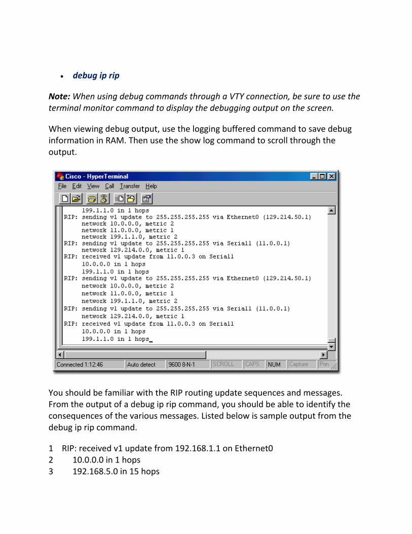
debug ip rip
Note: When using debug commands through a VTY connection, be sure to use the terminal monitor command to display the debugging output on the screen.
When viewing debug output, use the logging buffered command to save debug information in RAM. Then use the show log command to scroll through the output.
You should be familiar with the RIP routing update sequences and messages. From the output of a debug ip rip command, you should be able to identify the consequences of the various messages. Listed below is sample output from the debug ip rip command.
1 RIP: received v1 update from 192.168.1.1 on Ethernet0 2 10.0.0.0 in 1 hops 3 192.168.5.0 in 15 hops

4 RIP: sending v1 update to 255.255.255.255 via Serial0 (192.168.2.201) 5 network 10.0.0.0, metric 2 6 network 192.168.1.0, metric 1 7 network 192.168.5.0 in 16 hops (inaccessible) 8 RIP: received v1 update from 192.168.2.202 on Serial0 9 192.168.3.0 in 1 hops 10 192.168.4.0 in 2 hops 11 RIP: sending v1 update to 255.255.255.255 via Ethernet0 (192.168.1.201) 12 network 192.168.2.0, metric 1 13 network 192.168.3.0, metric 2 14 network 192.168.4.0, metric 3
The following table interprets each line in the sample output.
Line Number(s)
Meaning
1, 8
This line identifies the router and the interface where RIP updates are received. In this example, the router is connected to two other routers:
Router 192.168.1.1 on Ethernet0 Router 192.168.2.202 on Serial0
2‐3, 9‐10
Indented below each RIP line are the specific routing entries that are received. This example shows the following routes received:
10.0.0.0 and 192.168.5.0 from router 192.168.1.1 on Etherent0
192.168.3.0 and 192.168.4.0 from router 192.168.2.202 on Serial0
The hop count shown in the received route will be the metric used when the route is placed in the routing table of the local router.
4, 11
This line identifies the interface on which RIP updates are sent. In this example, the following interfaces have been enabled to share RIP information:
Serial0 with an IP address of 192.168.2.201 Ethernet0 with an IP address of 192.168.1.201
This means that the following commands have been entered on the router: router rip network 192.168.1.0 network 192.168.2.0
5‐7, 12‐14
Indented below the RIP line are the entries that are shared with other routers. Be aware of the following items:
Before sending the information, the router increments the hop count. To identify the hop count in the local routing table, subtract 1 from the sent hop count.
Line 7 (network 192.168.5.0) is advertised as inaccessible (16 hops). This is because the local router has a hop count of 15 for that network. 16 hops is the maximum hop count for RIP.
For comparison, here's how the routing table of the local router would appear:
R 10.0.0.0/8 [120/1] via 192.168.1.1, 00:00:05, Ethernet0 C 192.168.1.0/24 is directly connected, Ethernet0 C 192.168.2.0/24 is directly connected, Serial0 R 192.168.3.0/24 [120/1] via 192.168.2.202, 00:00:04, Serial0 R 192.168.4.0/24 [120/2] via 192.168.2.202, 00:00:04, Serial0 R 192.168.5.0/24 [120/15] via 192.168.1.1, 00:00:05, Ethernet0
© Sergey Gorokhod MCT/MCSE/MCITP/MCTS/MCSA/CCSE/CCSA/CCNA/A+® E‐mail: [email protected] Mob: (+972) 526848757

10.7. RIP Practice Network Diagram
The next five Labs all use the same network diagram. Your task will be to configure one of the routers from scratch to connect to the network and share routing information with the other routers. As you work through your configuration, keep in mind the following:
Check the connected routers to identify the network mask used on each network. Then select an IP address that is not already in use on the network (i.e. select a different address than the one to which the router you are configuring connects).
Use show commands and other techniques to check your work. When you are finished, the sh ip route command should display all the networks shown in the diagram.
The ping command is available for troubleshooting if you need it, but the traceroute command is not enabled in the simulation.
If you are following the Networking Academy curriculum, you will be required to complete the following tasks in class that are not required in this simulation:
o Identify routers throughout the network with the ip host command. o Disable DNS lookup with the no ip domain‐lookup command. o Disable IP classless with the no ip classless command.
Shown here is the network diagram used for all five scenarios.

10.8. OSPF Troubleshooting
When troubleshooting OSPF configuration, remember that OSPF routers share route information only with adjacent neighbor routers. The following conditions must be met for two routers to become fully adjacent:
Both routers must be on the same subnet and use the same subnet mask. Both routers must have the same hello and dead intervals configured. Both routers must use the same OSPF area. If authentication is required, both routers must pass the authentication
requirements. Both routes must be using the same area type (stub area flag).
Note: The process ID used when configuring OSPF does not need to match between routers.
The following table lists some commands that are useful in monitoring and troubleshooting OSPF.
Command Function
show ip protocols
Use show ip protocols to view OSPF configuration information such as:
The OSPF process ID The OSPF router ID for the current router Configured networks and areas for the process IP addresses of neighbor routers
show ip ospf
Use show ip ospf to view OSPF information including:
The process ID The local router ID and its role (such as DR or BDR) Configured areas

show ip ospf neighbor
Use show ip ospf neighbor to view information about neighbor OSPF routers including:
Router ID of the neighbor router Neighbor state or status (the Full state indicates that the
DR/BDR election has occurred and they are exchanging routing information)
The role of the neighbor (DR, BDR, DROTHER) Time remaining before the neighbor is declared missing if a
hello packet is not received The IP address of the neighbor The local interface used to reach the neighbor
show ip ospf interface
Use show ip ospf interface to view interfaces that are running OSPF including the following information:
Interface status and IP address assigned to the interface Area number Process ID Router ID The router ID and IP address of the DR and BDR on the
network Hello and dead timer settings Adjacent routers
debug ip ospf events
Use debug ip ospf events to view debugging information about hello exchanges, DR selection information, SPF calculation, and errors related to negotiating adjacency.
Use debug ip ospf hello to view only hello packet information.
Use debug ip ospf adj to view adjacency information.
Most error messages shown in the debug output adequately describe the nature of the problem. Shown below are some errors that display with the debug ip ospf events command:

Error Meaning
OSPF: mismatched hello parameters from 10.0.0.1 OSPF: Dead R 20 C 40, Hello R 5 C 5 Mask R 255.255.255.0 C 255.255.255.0
Hello timer, dead timer, or subnet mask mismatch detected. In this example, the dead timer intervals do not match: R (received) = 20, C (configured) = 40
OSPF: hello packet with mismatched E bit
Area types (not area numbers) configured on each router do not match. The E bit is also called the stub area flag.
Neighbor Down: Dead timer expired
An expected hello timer has not been received. When the dead timer reaches 0, it is assumed that the neighbor router has gone down. The dead timer resets itself each time a hello packet is received.
© Sergey Gorokhod MCT/MCSE/MCITP/MCTS/MCSA/CCSE/CCSA/CCNA/A+® E‐mail: [email protected] Mob: (+972) 526848757

10.9. EIGRP Troubleshooting
When troubleshooting EIGRP, keep in mind that the following conditions must be met for an EIGRP router to share information with a neighbor:
Both routers must be on the same subnet with the same subnet mask. If used, authentication checks must pass. Both routers must be configured with the same AS number. Metric weight values (K values) must match on both routers.
Note: Hello intervals do not need to match for EIGRP.
The following table lists some commands you can use to verify EIGRP.
Command Function
show ip protocols
Use show ip protocols to view:
EIGRP autonomous system number Configured networks K values and variance Neighbor router IP addresses
Note: In the labs, this is the only listed troubleshooting command that has been enabled.
show ip eigrp interfaces
Use show ip eigrp interfaces to view interfaces that are sending and receiving EIGRP updates. Passive interfaces will not be shown.
show ip eigrp neighbors
Use show ip eigrp neighbors to view the following information for neighbor routers:
IP address Local interface to reach the neighbor router
show ip eigrp topology
Use show ip eigrp topology to view the contents of the topology table for EIGRP. Information for each known network includes:
The number of successor routes to that network.

The feasible distance (FD) for the network. Feasible successors to that network.
Show ip eigrp topology only shows feasible success routes (routes whose AD is less than the network FD). To view all routes, including those that did not qualify as feasible successor routes, use show ip eigrp topology all‐links.
The following example shows some sample output from the show ip eigrp topology all‐links command.
Router# show ip eigrp topology all‐links IP‐EIGRP Topology Table for process 77 Codes: P ‐ Passive, A ‐ Active, U ‐ Update, Q ‐ Query, R ‐ Reply, r ‐ Reply status P 172.16.90.0 255.255.255.0, 2 successors, FD is 46251776 via 172.16.80.28 (46251776/46226176), Ethernet0 via 172.16.81.28 (46251776/46226176), Ethernet1 via 172.16.80.31 (46277376/46251000), Serial0 P 172.16.81.0 255.255.255.0, 1 successors, FD is 307200 via 172.16.82.28 (307200/281600), Ethernet1 via 172.16.80.28 (308500/281600), Ethernet0 via 172.16.80.31 (332800/307900), Serial0
Important items in the command output are explained in the following table:
Information Description
Destination network
Each destination network is indicated by a subsection in the command output. For example, the route 172.16.90.0 has the following information:
P = The computational status of the route. A status of P means that the route has been calculated and the router is not waiting for information or calculating information for the route. A passive state indicates a converged route.
Network address and mask

2 successors = the number of successor routes to that network. Successor routes are the best feasible successor routes. Successor routes meet the following conditions:
o Their advertised distance (AD) is less than the feasible distance for the network.
o Their total cost is the lowest of the total cost for all feasible successor routes.
FD is 46251776 = The feasible distance (FD) to the network. The FD for the network is the lowest total cost of all routes to the destination network at the time that routes were calculated.
Known routes
Known routes to the destination are identified by the via entries. For example, the first route for network 172.16.90.0 shows the following information:
172.16.80.28 = The next hop router address. 46251776 = The total cost to the destination network. The
total cost is calculated by the router by taking the advertised cost and adding the actual bandwidth and delay to reach the next hop router. Be aware that the total cost value is sometimes called the feasible distance of the route; however, this is not the same thing as the feasible distance of the network. Note: The total cost of the first route typically matches the FD for the destination network. However, the values will not necessarily match.
46226176 = The advertised distance (AD) to the destination (also called the reported distance (RD)). This is the distance as reported by the next hop router.
Ethernet0 = The local router interface used to reach the next hop router.

Successor routes
Successor routes are identified by taking the number of successors and counting down the list of known routes. In this example for network 172.16.90.0, there are 2 successors, meaning that 172.16.80.28 and 172.16.81.28 are both successor routes.
Feasible successor routes
Feasible successor routes are additional routes that match the following requirement: The AD for the route must be lower than the FD for the network. Note: Any route that matches this condition is called a feasible route. This includes those routes that are the successor routes (a successor route is a feasible route, but not every feasible route is a successor route).
This requirement ensures that the route is loop free. For network 172.16.90.0, all three routes listed are feasible routes because their AD cost is less than 46251776. For network 172.16.81.0, the last route is not a feasible successor route because its AD (307900) is greater than the FD for the route (307200). Note: This last route would not have shown if the show ip eigrp topology command was used without the all‐links parameter.
© Sergey Gorokhod MCT/MCSE/MCITP/MCTS/MCSA/CCSE/CCSA/CCNA/A+® E‐mail: [email protected] Mob: (+972) 526848757