10gepon burst receiver simulation - ieee 802 · 2008-01-24 · 10gepon burst receiver simulation...
TRANSCRIPT
P M C - S I E R R A
1 IEEE 802.3av Portland, Oregon January 2008
10GEPON Burst ReceiverSimulation
IEEE 802.3avJanuary 2008
Haim Ben-AmramPortland, Oregon

P M C - S I E R R A
2 IEEE 802.3av Portland, Oregon January 2008
Outline
The LIA Model- AC Coupled- DC Coupled
ResultsConclusions
P M C - S I E R R A
3 IEEE 802.3av Portland, Oregon January 2008
10GEPON AC Coupled
P M C - S I E R R A
4 IEEE 802.3av Portland, Oregon January 2008
10G LIA – Transfer Function
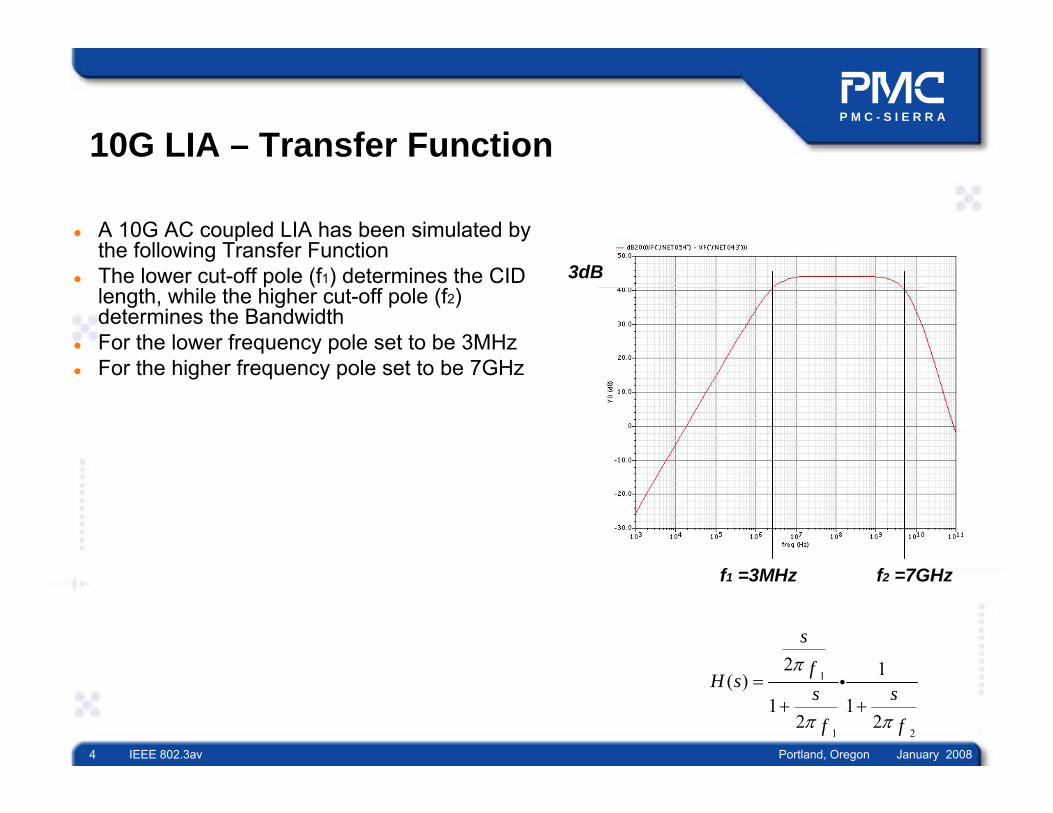
A 10G AC coupled LIA has been simulated by the following Transfer FunctionThe lower cut-off pole (f1) determines the CID length, while the higher cut-off pole (f2) determines the Bandwidth For the lower frequency pole set to be 3MHzFor the higher frequency pole set to be 7GHz
3dB
f1 =3MHz f2 =7GHz
1
1 2
2 1( )1 1
2 2
s
fH s
s s
f f
π
π π
=+ +
i
P M C - S I E R R A
5 IEEE 802.3av Portland, Oregon January 2008
Considerations in choosing the frequency poles
The higher frequency determines the Bandwidth of the LIA- Therefore the higher frequency pole set to be 7GHz as it should be 0.7B, where B =
10Gbps The lower frequency determines the CID length and how much DC droop from the baseline is allowed
- The lower frequency set to be 3MHz to support 64 bits of CID and maximum 6% DC droop
If the lower frequency cut-off will be too low than the optimum level, it will cause Jitter due to Flicker Noise If it will be too high then it will cause too large DC droop

P M C - S I E R R A
6 IEEE 802.3av Portland, Oregon January 2008
Considerations in choosing the Coupling Capacitor
In AC Coupled applications with long CID the coupling capacitor generates Pattern Dependent JitterIn order to minimize this Jitter, the low frequency cut-off should be optimal as possibleIn one hand, the low frequency cut-off must be as close to DC as possible to avoid baseline DC droop and ISI (which close the EyeDiagram Vertically). In other hand, if the low frequency cut-off will be too low than the optimum it cause to long preamble
P M C - S I E R R A
7 IEEE 802.3av Portland, Oregon January 2008
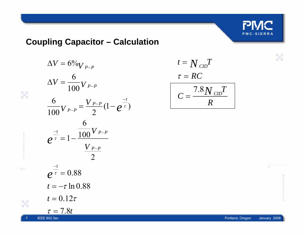
Coupling Capacitor – Calculation
6%
6100
6 (1 )100 2
61001
2
0.88ln 0.88
0.127.8
P P
P P
tP P
P P
t P P
P P
t
V V
V V
VV
V
V
tt
t
e
e
e
τ
τ
τ
ττ
τ
−
−
−−
−
− −
−
−
∆ =
∆ =
= −
= −
=
= −==
7.8
CID
CID
t T
RCT
CR
N
Nτ
=
=
=
P M C - S I E R R A
8 IEEE 802.3av Portland, Oregon January 2008
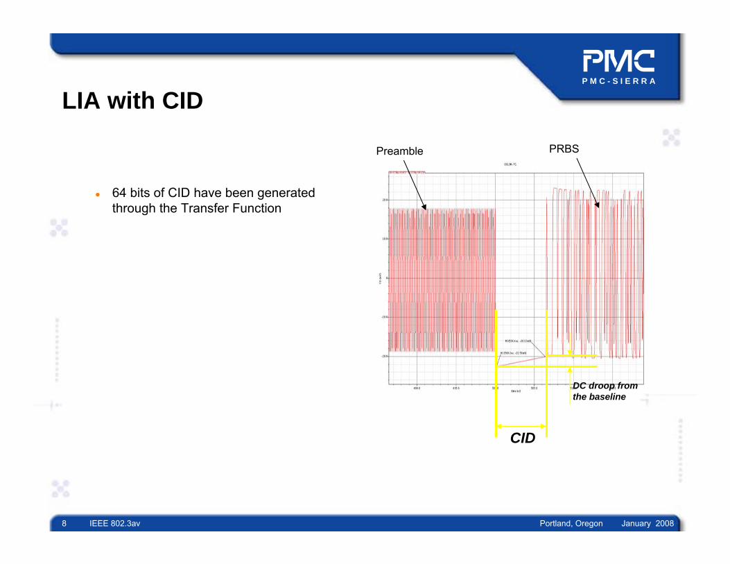
LIA with CID
64 bits of CID have been generated through the Transfer Function
CID
DC droop from the baseline
Preamble PRBS

P M C - S I E R R A
9 IEEE 802.3av Portland, Oregon January 2008
LIA – Conclusion
We have found, by the simulation, that 3MHz as a low frequency cut-off is the optimum value to maintain CID of 64 bitsThis low frequency cut-off has about 2500bits(250ns) preamble length
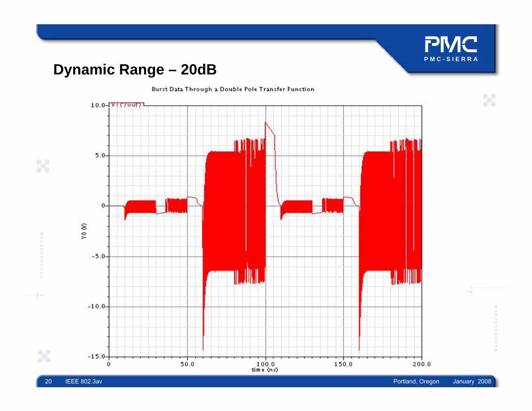
20dB Dynamic Range
250ns

P M C - S I E R R A
10 IEEE 802.3av Portland, Oregon January 2008
10GEPON DC Coupled

P M C - S I E R R A
11 IEEE 802.3av Portland, Oregon January 2008
10G LIA – DC Coupled
In DC Coupled the τ (RC) determined by internal 2 CapacitorsOne capacitor for “fast” acquisition, during preamble, and the second for CID supportDuring Preamble, the threshold acquisition done by “Middle”frequency cut-off pole Once the threshold acquired then it switch to “low” frequency cut-off pole to support CID
P M C - S I E R R A
12 IEEE 802.3av Portland, Oregon January 2008
AKWS
WSS
WSAS
VV
HL
L
in
out
+⎟⎟⎠
⎞⎜⎜⎝
⎛+⎟⎟
⎠
⎞⎜⎜⎝
⎛+
⎟⎟⎠
⎞⎜⎜⎝
⎛+
=11
1
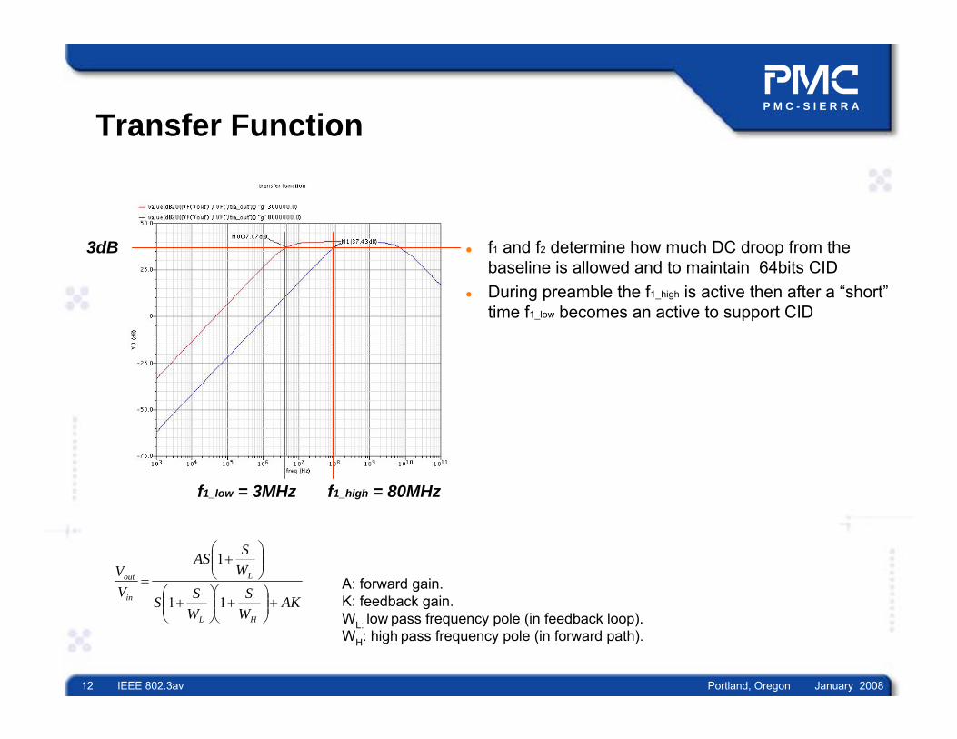
A: forward gain.K: feedback gain.WL: low pass frequency pole (in feedback loop).WH: high pass frequency pole (in forward path).
Transfer Function
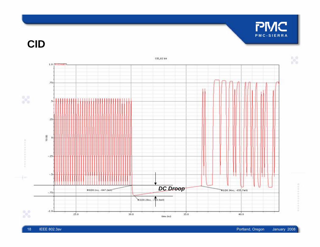
f1 and f2 determine how much DC droop from the baseline is allowed and to maintain 64bits CIDDuring preamble the f1_high is active then after a “short”time f1_low becomes an active to support CID
3dB
f1_low = 3MHz f1_high = 80MHz
P M C - S I E R R A
13 IEEE 802.3av Portland, Oregon January 2008
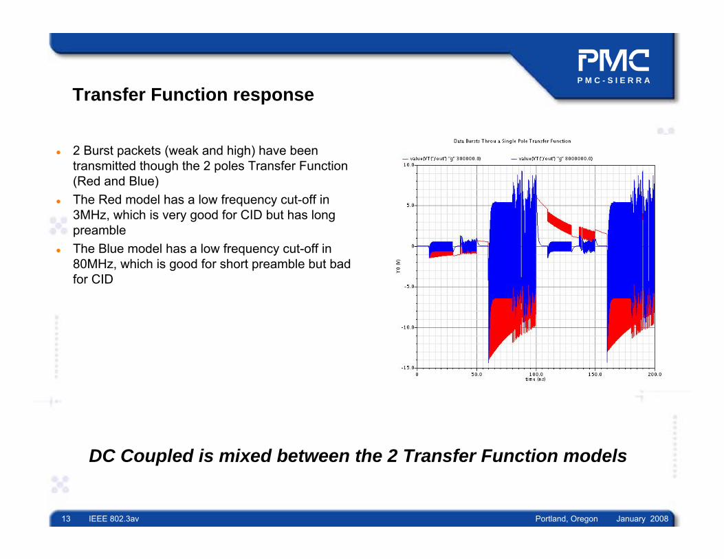
Transfer Function response
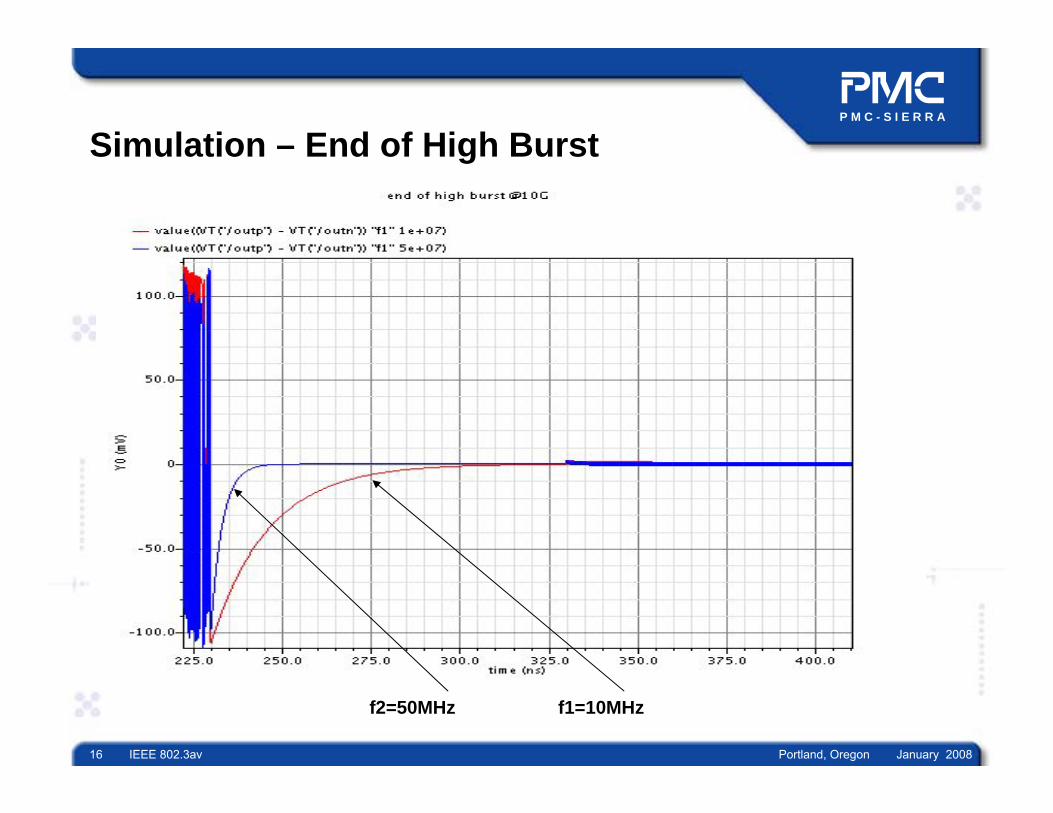
2 Burst packets (weak and high) have been transmitted though the 2 poles Transfer Function (Red and Blue)The Red model has a low frequency cut-off in 3MHz, which is very good for CID but has long preambleThe Blue model has a low frequency cut-off in 80MHz, which is good for short preamble but bad for CID
DC Coupled is mixed between the 2 Transfer Function models

P M C - S I E R R A
14 IEEE 802.3av Portland, Oregon January 2008
Simulation – Start of High Burst

P M C - S I E R R A
15 IEEE 802.3av Portland, Oregon January 2008
Simulation – CID
P M C - S I E R R A
16 IEEE 802.3av Portland, Oregon January 2008
Simulation – End of High Burst
f2=50MHz f1=10MHz

P M C - S I E R R A
17 IEEE 802.3av Portland, Oregon January 2008
Preamble Length
Preamble is stable after 5ns!
P M C - S I E R R A
18 IEEE 802.3av Portland, Oregon January 2008
CID
DC Droop

P M C - S I E R R A
19 IEEE 802.3av Portland, Oregon January 2008
Guard Time
High Burst
CID Pole – End of Burst Preamble Pole – End of Burst
Weak Burst
P M C - S I E R R A
20 IEEE 802.3av Portland, Oregon January 2008
Dynamic Range – 20dB

P M C - S I E R R A
21 IEEE 802.3av Portland, Oregon January 2008
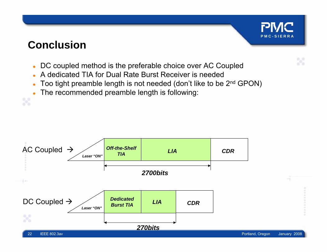
Conclusion – Preamble Length
LIAWe have assumed 6% DC droop from the baselineIn AC coupled the preamble length is:
- 2600bits
In DC coupled the preamble length is:- 50bits
P M C - S I E R R A
22 IEEE 802.3av Portland, Oregon January 2008
Conclusion
DC coupled method is the preferable choice over AC Coupled A dedicated TIA for Dual Rate Burst Receiver is neededToo tight preamble length is not needed (don’t like to be 2nd GPON)The recommended preamble length is following:
Laser “ON”
Off-the-Shelf TIA LIA CDR
2700bits
AC Coupled
DC Coupled Dedicated Burst TIA LIA
270bits
CDRLaser “ON”

P M C - S I E R R A
23 IEEE 802.3av Portland, Oregon January 2008
Back up
P M C - S I E R R A
24 IEEE 802.3av Portland, Oregon January 2008
V0
Vp-p /2
-Vp-p /2
CID “1”
V06%
Vmax
1t
e τ−
−
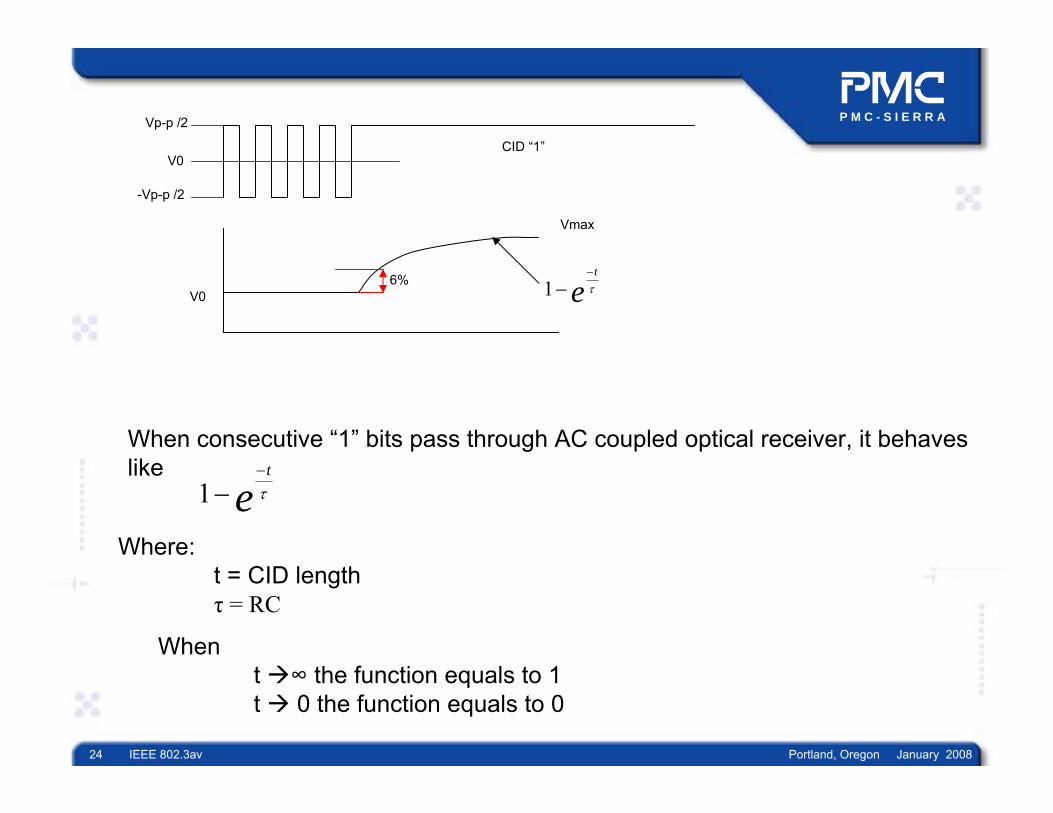
When consecutive “1” bits pass through AC coupled optical receiver, it behaves like
1t
e τ−
−
Where:t = CID length τ = RC
When t ∞ the function equals to 1 t 0 the function equals to 0

P M C - S I E R R A
25 IEEE 802.3av Portland, Oregon January 2008
An Example:Assumptions:Vp-p = 400mV∆V [k] = 6%t = 5.2τ
Eq 1
Eq 2
Eq 1 + Eq 2
CIDt TN=
For :k=6%NPreamble = 2600 bits
(1 )100 2
(1 )100 2
1001
2
ln(1 )50
tp p
p p
tp p
p p
t p p
p p
k VV V
k VV
kV
V
kt
e
e
e
τ
τ
τ
τ
−−
−
−−
−
− −
−
∆ = = −
= −
= −
= − −
ln(1 )50CID
kTN τ= − −
ln(1 )50
CIDTk
Nτ−
=−
5.2
5.2*
ln(1 )50
PREAMBLE
CIDPREAMBLE
T
Nk
N
N
τ=
−=
−
P M C - S I E R R A
26 IEEE 802.3av Portland, Oregon January 2008
0.5Vptp_max
10%Vptp_min
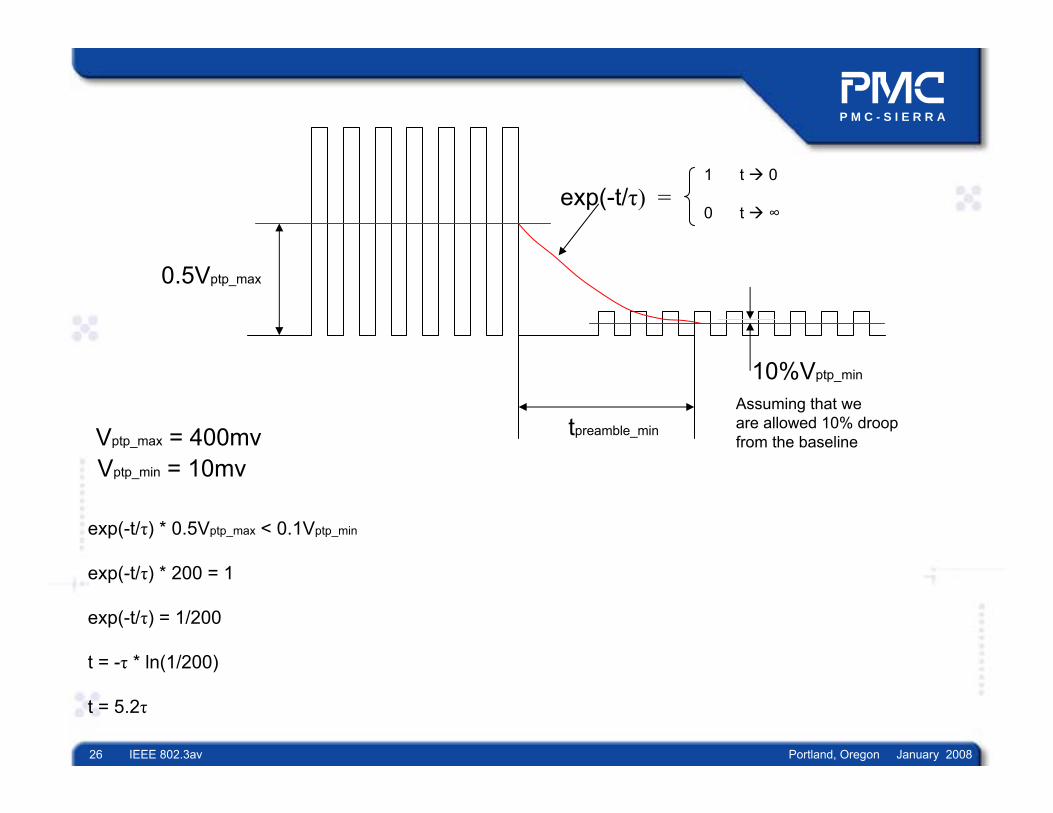
Assuming that we are allowed 10% droop from the baseline
tpreamble_min
exp(-t/τ) =
Vptp_max = 400mvVptp_min = 10mv
exp(-t/τ) * 0.5Vptp_max < 0.1Vptp_min
exp(-t/τ) * 200 = 1
exp(-t/τ) = 1/200
t = -τ * ln(1/200)
t = 5.2τ
1 t 0
0 t ∞

P M C - S I E R R A
27 IEEE 802.3av Portland, Oregon January 2008
A Formula – Preamble(CID)
Assuming that 5 time constants is needed
CID
preamble
X
NN
Where:
= Number of CID
= Required Preamble length [bits]= Deviation of baseline permitted during CID
An example: CID = 64X = 0.1 (10%)
N = -5 * 64 ln(1 - 0.1) = 2430bits
N = -5 * 64 ln(1 - 0.06) = 5170bits
For 6% droop
5ln(1 )
cidpreamble
NNX
− ⋅=
−

P M C - S I E R R A
28 IEEE 802.3av Portland, Oregon January 2008
Straw poll #2
Do we maintain the sensitivity of the 1G OLT receiver (PX10 and PX20) ?Yes: _29_No: _0_No opinion: _2_